Publisher’s version / Version de l'éditeur:
Corrosion, 50, Dec 12, pp. 907-911, 1994-12-01
READ THESE TERMS AND CONDITIONS CAREFULLY BEFORE USING THIS WEBSITE. https://nrc-publications.canada.ca/eng/copyright
Vous avez des questions? Nous pouvons vous aider. Pour communiquer directement avec un auteur, consultez la première page de la revue dans laquelle son article a été publié afin de trouver ses coordonnées. Si vous n’arrivez pas à les repérer, communiquez avec nous à [email protected].
Questions? Contact the NRC Publications Archive team at
[email protected]. If you wish to email the authors directly, please see the first page of the publication for their contact information.
NRC Publications Archive
Archives des publications du CNRC
This publication could be one of several versions: author’s original, accepted manuscript or the publisher’s version. / La version de cette publication peut être l’une des suivantes : la version prépublication de l’auteur, la version acceptée du manuscrit ou la version de l’éditeur.
Access and use of this website and the material on it are subject to the Terms and Conditions set forth at
Distribution of steady-state cathodic currents underneath a disbonded
coating
Brousseau, R. J.; Qian, S. Y.
https://publications-cnrc.canada.ca/fra/droits
L’accès à ce site Web et l’utilisation de son contenu sont assujettis aux conditions présentées dans le site LISEZ CES CONDITIONS ATTENTIVEMENT AVANT D’UTILISER CE SITE WEB.
NRC Publications Record / Notice d'Archives des publications de CNRC:
https://nrc-publications.canada.ca/eng/view/object/?id=6de8d471-a94c-4980-bf7d-7f4b5f83c97e https://publications-cnrc.canada.ca/fra/voir/objet/?id=6de8d471-a94c-4980-bf7d-7f4b5f83c97e
http://www.nrc-cnrc.gc.ca/irc
I nve st iga t ion of t he ra pid c hloride pe rm e a bilit y t e st
N R C C - 3 5 5 2 5
F e l d m a n , R . F . ; C h a n , G . W . ; B r o u s s e a u , R . J . ;
T u m i d a j s k i , P . J .
M a y 1 9 9 4
A version of this document is published in / Une version de ce document se trouve dans:
ACI Materials Journal, 91, (3), pp. 246-255, May, 1994
The material in this document is covered by the provisions of the Copyright Act, by Canadian laws, policies, regulations and international agreements. Such provisions serve to identify the information source and, in specific instances, to prohibit reproduction of materials without written permission. For more information visit http://laws.justice.gc.ca/en/showtdm/cs/C-42
Les renseignements dans ce document sont protégés par la Loi sur le droit d'auteur, par les lois, les politiques et les règlements du Canada et des accords internationaux. Ces dispositions permettent d'identifier la source de l'information et, dans certains cas, d'interdire la copie de documents sans permission écrite. Pour obtenir de plus amples renseignements : http://lois.justice.gc.ca/fr/showtdm/cs/C-42
CORROSION SCIENCE
Distribution of Steady-State Cathodic Currents
Underneath a Disbanded Coating*
R. Brousseau and S. Qian*
ABSTRACT
Pipeline corrosion frequently persists underneath disbonded coatings on pipelines that appear to be well protected cathodically. Application of higher cathodic potentials for improved protection may produce hydrogen gas (H2Jbubbles that block current flow underneath
a
disbonded coating.Aproject was undertaken to determine whether an increase in applied potential results in higher polarization levels on the crevice steel underneath
a
disbonded coating. Witha higher applied potential, pH levels inacrevice should increase. Steady-state cathodic protection experiments were performed at three applied potentials in an electrochemical cell simulating the crevice steel under a disbonded coating. The recorded profiles showed that higher levels of protection underneath a disbonded coating could be achieved by applying higher cathodic potentials. Penetration of the cathodic currents underneatha
disbonded coating also was more difficult in higher resistivity solutions.KEY WORDS: cathodic protection, coatings, disbondment, hydrogen gas, pipeline corrosion, potential
INTRODUCTION
Buried or submerged pipelines usually are prevented from corroding by a combination of coatings and
*Submitted for publication January 1994; in revised form, May 1994. • National Research Council of Canada, Bldg. M-20, Montreal Road,
Ottawa, Ont., K1 A OR6, Canada.
cathodic protection. A coating has the basic function of isolating the steel pipe from a corrosive
environment. Cathodic protection completes the defense system by preventing the electrochemical dissolution of iron (Fe) by changing its potential. This reduces the likelihood of corrosion at defective areas of the pipe coating. Proper cathodic protection can be achieved on exposed steel, but when the coating is disbonded, proper protection is hard to achieve in the void or crevice formed between the coating and pipe.
Toncre has recommended more negative potentials of cathodic protection to achieve adequate polarization beneath disbonded pipe coatings.1-2This
suggestion has been supported by Orton, who obtained polarization up to -1,200 mVCSE2 in. from a
coating holiday when -1.5 VCSEwas applied to a test
pipe.3Charles obtained experimental data showing
increased cathodic polarization when more negative potentials were applied.4
However, Fessler, et aI., concluded that holiday potentials more negative than that required to form hydrogen (H2) bubbles would cause difficulty in
controlling the potential under the disbonded coating.sThis phenomenon is represented schematically in Figure 1. Cherry and Gould also have suggested that overprotection (e.g., a holiday potential of -1 ,500 mVSCE ) is undesirable.6
With this information, it has been difficult to determine the proper approach to obtain adequate corrosion control on pipelines.
Reprinted from CORROSION, Vol. SO, No. 12, pp. 907-911 (1994) December Copyright 1994 by NACE International, P.O. Box 218340, Houston, Texas 77218-8340
CORROSION SCIENCE
セ
Icp (steady state)hRセッキセhR . .
ow ow ow Disbanded coating
w o w0
FIGURE 1. H2bubbles formed on steel prevented OH- ions
from migrating underneath the disbonded coating.
The objective of the present work was to present additional experimental data to clarify that applying more negative potentials (up to-1.5 VSCE)increases
cathodic polarization underneath a disbonded coating.
EXPERIMENTAL
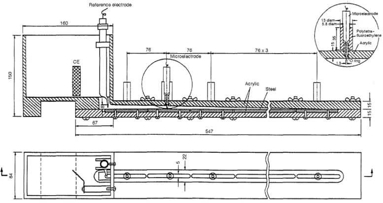
All experiments were performed in an electro-chemical cell designed to simulate a crevice that is found frequently in the field between a disbonded
Reference electrOde
160
coating and a steel pipe (Figure 2). The cathode consisted of polished low-carbon (C) steel strips that were polarized simultaneously. The counter electrode was made with a high-grade platinum (Pt) mesh. Potential and pH measurements in the crevice were recorded using microelectrodes that were calibrated carefully before and after each experiment. All potential measurements were reported vs the
saturated calomel reference electrode (SCE). A glass tube with averyfine tip was used as a luggin to extend the main reference electrode and reduce the ohmicvoltage (IR) drop caused by the current concentrated at the crevice opening.
The test solution was made of distilled water and consisted of 5 x10⁻⁴ M sodium bicarbonate
(NaHC03), 5 x10⁻⁴M calcium chloride (CaCI2), and
5 x10⁻⁴M tricalcium orthophosphate (Ca3[P04h),
unless specified otherwise. This solution was not bubbled with oxygen (02) or nitrogen (N2) during the
experiments.
To prevent any electrical loading by the measuring instruments on the microelectrodes, multimeters with an input impedance> 1012Q were
used. Some time delay was required before measurements to ensure that the potentials were stabilized. The steady-state potentials were applied and controlled using a high-power potentiostat.
908
N I Iセ
N I I BI!
I I I ( iセi ) ( @D
I 1 I ) I1
I : fI c: B IFIGURE 2. Schematic of the electrochemical cell simulating the crevice steel under a disbonded coating.
Dimensions are in millimeters
CORROSION SCIENCE
-j,."Potential; -1.5 VSCE .... Potential;-1.19VSCE .... Potential; -1.06 VSCE
MBGセJMッ ---,,---,---.,.,,'0----:-«--,--14--·:-::-,5--"8 Distance from Holiday (in.)
240 200 120 160 Time (h) 80 40 -1,100 -1 ,200 ャMM⦅セ _ ____'_ _..._ ___''___"""''__ __'_---..I
o
-1,000 -500 , . . - - - ,MVPPセセZ、
t:5MWPPャセ
セッ-S
-800 Ciiセ
-900セ
-500' J t - - - ,
(b) (a)FIGURE 4. Steel crevice potential after 250 h of cathodic
polarization at the indicated voltages.
RESULTS AND DISCUSSION
Effect of Higher Applied Cathodic Voltages
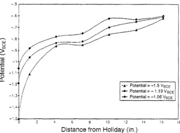
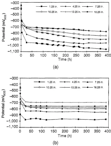
The potential-vs-time profiles recorded by microelectrodes along a crevice are plotted in Figure 3. Three cathodic potentials were applied at the crevice opening (i.e.,-1.06VSCE,-1 .19VSCE,
and
-1.5
VSCE ' A rapid increase in cathodicpolariza-tion was evident in the first 80 h of the test period. The increase was more accentuated near the crevice opening. This was followed by a leveling of the potential to a constant value. The levels of polariza-tion decreased with increasing distance from the crevice opening. Higher applied potentials promoted higher cathodic polarization along the entire crevice (Figure 4). Potential values were recorded after 250 h of cathodic polarization. Polarization increases with higher applied potentials were evident for all the steel segments, including those furthest from the crevice opening.
Effect of IR on Penetration
of Cathodic Currents
Pipelines surrounded by a disbonded dielectric coating in high resistivity waters can be difficult to protect adequately by cathodic protection. A higher electrolyte resistivity will reduce the penetration depth of the cathodic currents underneath a disbonded coating because of the larger IR drops.
Two steady-state experiments with an applied potential of-1 .19VSCEwere conducted using two
solutions with different resistivities. The more concentrated solution described in the experimental procedure had a resistivity of 5,070 Q-cm. The
120 160 200 240 Time (h) 80 80 120 160 200 240 Time (h) (c) 40 40 -1,100 -1 ,200 lM⦅セ _ _セ ⦅ セ _ _. L . . . _ _..._ _..1----'
o
-1,100 -1,200 L-_-'---'.-::.J=-_-'-_ _'---_-'-_--'----'o
-1,000 -600 1:5 -700セヲセセェ{ZZZZZ]MセZ]ZZZZ
>'
r
-S
-800 Cii .'§ -900 .8 o c.L -1,000 -500 , - - - , -600FIGURE3.Measured cathodic polarization along a simulated
crevice with time when: (a) -1.06 VSCE, (b) -1.19 VSCE' and
(c) -1.5 VSCE were applied at the crevice opening. Crevice
depth:'" = 1.25in.,
0
=
4.25in., •=
7.25in.,0 = 10.25in.,+= 13.25in., and X= 16.25in.
w u
>'
-700-S
Cii -800 セ 2 -900d:
CORROSION-Vol. 50, No. 12909
CORROSION SCIENCE - + - -Dilute SolutJon - - - 0 - -Normal Solution - 5 0 0 . . . - - - , -700 -600 w } -800
g
セ
-900 2 o a.. -1,000:
:
100 150 200 250 300 350 400 Time (h)---0---10.25 In. --+-1325 in. - - 16.25 in.
- - 1.25In. - + - - - 4.25 in. --....-. 7.25 In.
50 - 3 0 0 . . . . - - - , -400 W -500 ()
>(J)
-600g
-700 -800 -900 -1,000 -1,100+--+--+--+--+--+---I---.-,t----Ia
- - 1.25in. -+--- 4.25 In. --....-. 7.25 In.
---O---10.25In. --+-13.25In. - - 1 6 . 2 5 In.
(a) (2) 6 8 10 12 14 16 18 Distance (in.) -1,100 KMMセMMKMMKMMMKMMイMMMャMMMエMMMKMMMi o 2 4
FIGURE 6. Potential along a crevice after 388 h of cathodic polarization at-1.9 VSCE' One ofthe solutions was 10 times more dilute than the one described in the experimental procedure.
However, when the applied voltage is more negative than -1.2 VSCE ' a competing reaction also
can occur at an appreciable rate, particularly in the absence of O2 , Then, H2is evolved according to the
reaction: 50 100 150 200 250 300 350 400 Time (h) (b) -300
r
--400 セ -500 ';:%' -600g
-700 (ijE
-800 2 0 a.. -900 -1,000 -1,100+--+--+...--+--+--+--+---t---lo
FIGURE 5.Potential-vs-time profile along a crevice polarized at-1.19VSCE' The solution in (b) was 10 times more dilute than
in (a).
second solution was 10 times more dilute, with a resistivity of 31 ,250 Q-cm. Voltage time profiles are displayed in Figures 5(a) and (b). The cathodic polarization penetrated the crevice more easily when the resistivity of the solution was lowest.
Figure 6 shows the potential values recorded after 388 h of cathodic polarization for the two solutions. Results were in agreement with the observation that the cathodic currents also
penetrated deeper in the crevice when the resistivity of the solution was lowest. These current readings were taken from the individual steel segments used to make up the steel cathode in the electrochemical cell (Figure 1). Because of the rather large spread of the values, two scales were used to display the data in Figure 7.
Crevice pH Changes
During Cathodic Protection
When steel is polarized cathodically in aerated waters, the thermodynamically favored electrode reaction is O2reduction, which proceeds as:
These electrochemical processes involve the production of hydroxyl (OH-) ions (Le., a rise in pH).
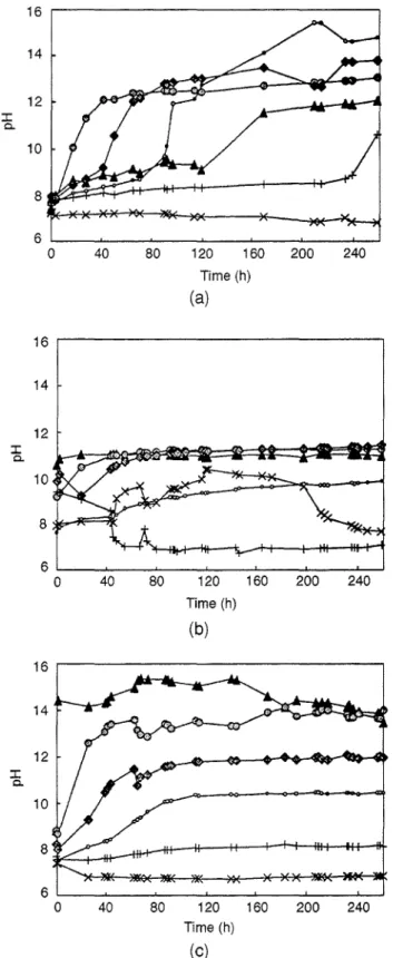
In the present study, pH values rose much more rapidly to a plateau near the crevice opening than in deeper regions. The highest pH values were
obtained near the opening and at higher applied cathodic potentials.
The pH profiles in a crevice were believed to depend strongly on the current densities, which were proportional to the rate of production of OH- ions. The pH change in the crevice over time is plotted in Figure 8. The crevice coating in the experiments was impermeable to O2,which is not always the case on
buried pipelines.
Although results in Figures 8(a) and (b) are rather erratic, a distinct progression of pH in the crevice with time is shown in Figure 8(c). The longer times involved for the increase in pH for the deeper areas also implied a certain amount of diffusion of the OH- ions. The concentration gradient was such that OH- ions built up at the opening slowly migrated away to eventually reach the deeper ends, as was found similarly by Payer, et al.7However, it was
anticipated that the rate of diffusion of the OH- ions at
20 5 450セZM[ZZ]]]]]]ZZZ[イMZ]M
==--I
400 \ I-·-Normal.olutlonl 21
I
350 \ I---Dilute .olutlon I!'
セ
300 \ ..."セRUP
\セッ
セセ
セ 200 -'0:---'5:---"":""0--':':"5--:205
150セ|
•. -_o----DI...-sta-nc-8-o n_..)o
100 50o
• • • •
-50+ - - - + - - - i - - - + - - - Jo
10 15 Distance (in.)FIGURE 7. Current along segments of steel cathode after
388 h of cathodic polarization in the two solutions. Inset shows current on an expanded scale.
the end of a crevice would depend greatly on its geometry and the availability of O2, 02-permeable coatings might improve the capacity of cathodic protection to move the pH in the crevice into a passive region.
CONCLUSIONS
.:. Higher applied cathodic voltages were shown to induce a deeper penetration of the cathodic currents underneath a disbonded dielectric coating. However, excessive cathodic protection is not necessarily advisable because of the possibility of H embrittle-ment of the pipeline steel or cathodic disbondembrittle-ment of the coating system .
•:. Voltage drops as a result of IR always favored a higher proportion of the cathodic currents to be collected by the steel at the crevice opening . •:. The cathodic currents penetrated less deeply under the disbonded coating in higher resistivity solutions .
•:. The chemical diffusion of the OH- ions helped to increase pH in the more remote sections of a crevice. REFERENCES
,. AC. Tonere, N. Ahmad, MP 6 (1980): p. 39. 2. A.C. Tonere, MP 8 (1984): p. 22.
3. M.D. Orton, MP 6 (1985).
4. EA Charles, J. Congleton, R.N. Parkins, Corros. Sci. 44, 9 (1988): p.599.
5. R.R. Fessler, AJ. Markworth, R.N. Parkins, Corrosion 39, 1 (1983). 6. B.W. Cherry, AN. Gould, MP 8 (1990): p. 22.
7. K. Fink, J.H. Payer. R. Savinell, "Mitigation of Corrosion by MOdification of the Environment Beneath Disbonded Coatings on Pipelines", CORROSION/93, paper no. 578 (Houston, TX: NACE, 1993).
VャNNNM⦅MGM⦅MMGセ⦅MGM⦅MMG _ __'__ _J . . _ _ J
o
40 80 120 160 200 240Time (h)
(c)
FIGURE8.pH-vs-time profile of a simulated crevice under
a
disbonded coating when steady-state cathodic polarization was applied at: (a)-1.06 VSCE'(b)-1.19 VSCE'and (c)-1.5 VSCE'
Crevice depth: ..
=
1.25in., 0=
4.25in., •=
7.25in.,0=
10.25 in., += 13.25in., andX = 16.25in.