Automated Alkalinity Sensing System
byYiou Wang Electronics Engineering BEng., University of York (2014)
Submitted to the Department of Mechanical Engineering in Partial Fulfillment of the Requirements for the Degree of
Master of Science At the
MASSACHUSETTS INSTITUTE OF TECHNOLOGY
June 2019
0 2019 Massachusetts Institute of Technology. All rights reserved
Signature redacted
Signature of Author ...
Department of MechanicaEngineering
Signature redacted
May 16,2019Certified by ... Accepted by... MASSACHUSETTS INSTITUTE OF TECHNOLOGY,
JUN
13
2019
LIBRARIES
... ... Michael S Triantafyllou Professor of Mechanical and Ocean Engineeringiesis Supervisor
Signature redacted..
...
....
Nicolas Hadjiconstantinou Professor; Co-Director of Computation r Design and Optimization Chairman, Committee on Graduate Students
Automated Alkalinity Sensing System
by
Yiou Wang
Submitted to the Department of Mechanical Engineering on May 16, 2019 in Partial Fulfillment of the Requirements for the Degree of Master of Science in
Mechanical Engineering
Abstract:
Ocean Acidification is a reduction in pH caused by the absorption of atmospheric C02. Low pH decreases the availability of calcium carbonate to shell and skeleton secreting marine animals such as mollusks and corals reducing their growth rates and even causing death. Thus, monitoring oceanic conditions has become more and more important, in particular there is a need for extensive measurements of carbonate chemistry parameters over both space and time. This paper presents a low-cost, automated benchtop measuring system for total alkalinity, one of the important parameters for monitoring marine carbonate chemistry. This system addresses the need for a low-cost alkalinity sensing system that can be deployed in great numbers to provide the large data sets needed for to measure and predict the impact of ocean acidification on the marine ecosystem. It is based on a two-point acid titration method. Tests of the prototype have shown that the system gives acceptable results comparable to manual measurements. With hermetic repackaging, the system could be field deployed on platforms such as AUVs or buoys.
Keywords:
Ocean Acidification; automated measurement; seawater; alkalinity measurement; data analysis.
Thesis Supeivisor: Michael S Triantafyllou
Title: Henry L. and Grace Doherty Professor in Ocean Science and Engineering ; Professor of Mechanical and Ocean Engineering ; Director, MIT Sea Grant College Program
Acknowledgments
My sincere thanks go to Prof. Triantafyllou, and Prof. Karniadakis, who provided me an opportunity to work at MIT Sea Grant. Without their precious support it would not be possible to conduct this research
I would like to express my sincere gratitude to Dr. Consi for the continuous support of my study and related research, for his patience, motivation, and immense knowledge. His guidance helped me in all the time of research and writing of this thesis.
I would like to thank my family for supporting me spiritually throughout writing this thesis and my life in general.
Cover Page Abstract: 2 Keywords: 2 Acknowledgments 3 Introduction: 5 Theory: 7 Hardware: 10 Arduino: 13
- Tentacle Mini Shield 14
- Motor Shield 15
- Data Logging Shield 15
Framing: 16
Sensors: 17
- Liquid level sensor 17
- Temperature probe 17
- PH probe 17
Titrator: 18
- Stepper motor 18
- Modification of the Digital Titrator 18
- Shaft coupling 20 Holder 20 Test chamber 20 Motors: 23 - Liquid pump 23 - Solenoid valve 23
- Analog Hot Plate/Stirrers 23
Software: 25
Working flow: 30
Tests and Results: 31
- Outcomes and compares 31
- Data analysis 33
- Design analysis 35
Conclusion: 35
References: 36
Appendix A. Arduino Source Code 39
Introduction:
During the past 40 years, with the rapid development of human industry, global atmospheric C02 has gradually increased from 338 to 408 ppm. As a portion of the anthropogenic C02 was absorbed by oceans, the pH value of seawater has decreased by 0.1 (Morse et al., 2007). This phenomenon is known as Ocean Acidification (OA). Lower pH will reduce the amount of bioavailable calcium (aragonite) which must be at saturation concentrations for shell-bearing marine animals to survive. Aragonite concentration (Q) can be calculated from measurements of partial pressure of C02 (pCO2), total hydrogen ion concentration (phot), total alkalinity (AT), and total dissolved inorganic carbon (CT also known as DIC) - these are the so-called Omega master variables. The more seawater is saturated with calcium carbonate, the faster the rate of mineral precipitation (Morse et al., 2007) and the less energy it takes to produce a shell. However, as seawater becomes less saturated with increasing pH as a result of OA, an organism needs to expend additional energy for shell production reducing its growth rate and, ultimately, resulting in death. These animals (e.g. Oysters, mussels, corals) are both commercially important species and important to the ocean ecosystem. In this way OA negatively affects the ocean ecosystem and the seafood industry. (Gledhill et al., 2015,)
Faced with this problem, we need to monitor ocean conditions with accurate sensors to protect the marine environment and, therefore, protect these marine organisms. In recent years, diverse sensors have been manufactured that have enabled great advances in our knowledge of ocean chemistry and man's impact. Nevertheless, there are evident limitations of the existing measurement instruments. For instance, a spectrophotometer
may be configured to accurately measure pH by (1) performing automated benchtop
analyses on discrete bottle samples collected by a ship rosette (Carter et al., 2013), (2)
running continuous underway measurements on flowing seawater (Bellary et al., 1995),
or (3) operating autonomously in situ for extended periods (Martz et al., 2003). Such
purpose-built, expensive instruments are intended for and generally restricted to
specific, rather than universal, applications. Consequently, instrumentation to measure
a given Omega master variable may not be readily available for a particular study.
Furthermore, without training in both seawater carbonate chemistry and engineering,
scientists often find that replicating a system described in the literature is either
untenably time consuming or completely intractable.
Coastal ocean acidification is an even more complex problem than OA in the open
ocean due to inputs from land and the higher biological load. The need for data is
greater than ever for current ocean acidification (OA) research. To address the need
for data, new, low-cost but accurate sensors and sensor systems are needed. The most
pressing need is for extensive (many) measurements in both space in time. There is a
fundamental tradeoff between cost and accuracy in sensors and sensing systems. For
Alkalinity measurements this can be seen in expensive but highly accurate
laboratory-based measurements (often for oceanography) vs. moderately accurate but low-cost
alkalinity test kits for manual measurements in aquaculture and stream and lake
monitoring. This thesis addresses the need for extensive measurements through the
development of a low-cost and moderately accurate sensor system that has the potential
of being deployed in large numbers in the field. The basic idea is to automate a standard
alkalinity test kit using low-cost readily available components.
Theory:
We can calculate the aragonite saturation state, if we know any two of the master variables, partial pressure of C02 (pCO2), total hydrogen ion concentration (phot), total alkalinity (AT), and total dissolved inorganic carbon (CT also known as DIC). The carbonate system is most accurately defined by measuring either pH or pCO2 in combination with either AT or CT. However, currently only pH and pCO2 can be measured by situ instruments. Some progress has been made toward in situ CT measurements, though. Benchtop automated, flow-through instruments have been developed for AT analysis, and an in situ potentiometric AT titrator was developed, for manual measurements. (Spaulding et al., 2019). Thus, AT data are currently obtained either from shipboard measurements during cruises or intense efforts with manual or robotic sample collection followed by manual analysis.
Alkalinity is the water's ability to oppose changes in pH that would make the water progressively acidic. (It ought not be mistaken for basicity which is an absolute measurement on the pH scale.) Alkalinity is the quality of a buffer solution made out of weak acids and their conjugate bases. It is estimated by titrating the solution under test with a monoprotic acid, like hydrochloric acid (HCI) until its pH changes suddenly, or it achieves a known endpoint where that occurs. Unit of Alkalinity is meq/L (milliequivalents per liter), which relates to the measure of monoprotic acid used as a titrant in millimoles per liter.
A correlation between AT and salinity (and easy to measure property of sea water) has
factors. The following quote by Spaulding, et al. (2015) addresses these issues: "In many cases it is possible to estimate AT using a relationship with salinity or salinity and temperature, because evaporation, precipitation, and mixing strongly control AT. However, these conservative relationships are not always followed. For example, in the Sargasso Sea, AT is generally conservative with salinity, but a several month-long drawdowns of jimol kg-', likely due to coccolithophore calcification, was detected. After spring blooms in the northern Bay of Biscay, AT is consistently depleted by coccolithophore calcification, and thus nonconservative with salinity. In many coastal areas consistent salinity-AT relationships do not exist because of riverine inputs, CaCO3 dissolution, and anaerobic processes. On the Bering Sea shelf the relationship between A1 and salinity can be highly variable, due to coccolithophore calcification and CaCO3 mineralization. In coral reef ecosystems, AT variability is typically dominated by CaCO3 formation and dissolution. Thus, AT-salinity relationships should be used with caution in most ocean regions, and are not valid on coral reefs."
To fill the need for a low-cost automated alkalinity sensor system with the potential for stand-alone autonomous operation, a standard low-cost alkalinity test kit (Hach Alkalinity test kit model AL-DT) was automated. This test kit uses a colorimetric reagents and acid titration. The standard method of alkalinity testing is stated in the manual of the HACH digital titrator as follows. Phenolphthalein indicator is added to the sample which is then titrated with .16 N sulfuric acid until the solution turns from pink to clear which occurs at pH 8.3. The amount of sulfuric acid added is multiplied
by a factor to yield the Phenolphthalein alkalinity in mg/L. Bromocresol Green-Methyl
Red indicator is then added to the sample and the titration continues until the solution turns pink indicating a pH of 4.5. The total amount of sulfuric acid added during the
entire titration multiplied by a factor is the total alkalinity in mg/L. The contributions of hydroxide, carbonate and bicarbonate to the total alkalinity can be calculated from the Phenolphthalein and total alkalinities. Note for an accurate measurement it is necessary to have a priori knowledge of the approximate range of alkalinity in the sample, the endpoint pH of the second titration is adjusted according to that range.
The system was automated by using a stepper motor to replace the manual turning of the titrator, a pH sensor, a pump to fill the testing chamber and an Arduino microcontroller to control the process.
Hardware:
The whole system is designed with five different sections: framing, Arduino board,
sensors, titrator, and pumps. The automatic measuring system has a vertical setup.
The stepper motor and its holder are located at the top of the structure, connecting to
the digital titrator with a shaft coupling. Under the titrator, is the cartridge containing
sulfuric acid and a "J" shaped delivery tube. The bottom of 3D printed test chamber is
close to the end of delivery tube to ensure its tip will be submerged in the sample
liquid during the titration process. There is a pH sensor, a temperature sensor, a liquid level sensor, and a small magnetic spin bar inside of the test chamber that sits on a standard laboratory magnetic stirring plate. Two beakers are set beside the stirrer. One of the beakers is connected with the test chamber through a tube and a liquid pump, the other one is connected with to a tube and a solenoid valve to drain the
chamber. All the sensors are read, and the motors are controlled by an Arduino Mega
microcontroller. The system is powered by a 5V and 12V DC power supply. The
system is illustrated in Figure 1 and presented in block diagram form in Figure 2.
FD
F
[ rwB
-
IG
FL]
Figure / A utomatic Alkalinity Measuring System
A: Stepper motor
C: Hach titrator
E: Titration cartridge (H2SO4)
G: Delivery tube
I: Test Chamber
K: Framing
M: Wires of solenoid valve
B: Shaft coupling
D: E-Tape liquid level sensor
F: pH sensor
H: Temperature Sensor J: Input pump
L: Stirrer
ARDUINO
Switch
IndicateLght
-W
Fquid Level
Sensor
Data Logging
Shield
Motor Shield
PH CircuitTemperature
Circuit
Stepper
Motor
PH Probe
Temperatue- ens4&
Tentacle Mini Shield
(Carrier board)
Figure 2 Block Diagram
Arduino:
The Arduino Mega 2560 is the foundation of the control section in the automatic system. It is a microcontroller board based on the ATmega2560. It has many features that make it an excellent choice for controlling small mechatronics systems such as the alkalinity tester including: 54 digital input/output pins (of which 15 can be used as PWM outputs), it has 16 analog inputs, 4 UARTs (hardware serial ports), a 16 MHz crystal oscillator, a USB connection, a power jack, an ICSP header, flash memory 256 KB of which 8 KB used by bootloader, and a reset button. The Arduino programming language is a variant of C++.
A feature of the Arduino microcontroller is the availability of specialized interface boards (shields) that expand the capabilities of the basic controller. The alkalinity system is built on a stack of the following boards (see Figure 3):
1. Adafruit Data Logging Shield with an SD card slot for data storage and a battery-backed real-time clock.
2. Adafruit Motor/Stepper/Servo shield for driving motors.
3. The Tentacle Mini Shield that holds the controller boards for the pH and temperature sensors.
The system is powered with a laboratory benchtop power supply, 5VDC powers the board stack and 12VDC powers the motor shield.
Arduino setup:
-it
Figure 3 Arduino Set up. The Arduino Mega is the bottom board and the Tentacle Shield with the pH and temperature controller boards is on top.
-
Tentacle Mini Shield
This is a stackable Arduino shield to host and individually isolate up to two EZO sensor
circuits from Atlas Scientific to measure PH, Dissolved Oxygen, Electric Conductivity
(E.C.), Oxidation-Reduction Potential (ORP) and temperature (RTD). The tentacle
mini holds the pH and temperature sensor circuits in the measuring system. Each sensor
circuit consists of a microcontroller with sensor interface electronics and an 12C serial
communications link with the Arduino. With its built-in electrical isolation, sensors
won't interfere with each other. It also removes outside electrical noise that can
interfere with readings ("Whiteboxes", 2019).
I.
PH Circuit:
This EZOTM pH circuit has working range from 0.001 to 14.000 with 0.00 1 resolution
and +/- 0.002 accuracy (the circuit itself, the effect of the pH probe is not considered in
these specifications) and could response as fast as 1 reading per second. It supports I
14
I I
(pH = 7), 2 (pH=4&10), or 3 (pH=4&7&10) points calibration. It must be calibrated before use in the system ("Atlas Scientific", 2019).
II. Temperature Circuit:
This RTD (Resistance Temperature Detector) circuit has working range from
-126.000 'C to 1254 'C with 0.001 resolution and +/- (0.1O C + 0.0017* C) accuracy (the circuit itself, the effect from temperature probe does not included) and could response as fast as I reading per second. The circuit has an on-board data logging capability of 50 readings. It must be calibrated before use in the system
("Atlas Scientific", 2019).
- Motor Shield
This motor shield has ability to drive up to 4 DC motors or 2 stepper motors. It is used to control a stepper motor to automate the titrator, a pump to fill the test chamber pump, and a solenoid valve to drain the chamber. It consists of two dual H-bridge drivers with each bridge capable of handling up to 1.2A and motors from 4.5VDC to 13.5VDC, and a PWM driver chip to control motor speed. It communicates to the Arduino via the 12C bus ("Adafruit Industries", 2019; "Adafruit Motor/Stepper/Servo Shield for Arduino v2
Kit").
- Data Logging Shield
This Data Logging Shield could save data to files on any FAT]6 or FAT32 formatted SD card, to be read by any plotting, spreadsheet or analysis program. It is interfaced to the Arduino via the SPI bus. Its onboard RTC (Real Time Clock) talks to the Arduino
2
via the 12C bus and is used to timestamp data with the current time. A back-up battery maintains the time when the system is powered down ("Adafruit Industries", 2019. "Adafruit Assembled Data Logging shield for Arduino").
Framing:
The 1010 Series of T-Slotted Aluminum Extrusion (80/20) with its fasteners, mounts and accessories have been used for framing structure. This is an extremely durable component, constructed from aluminum and clear anodized for corrosion resistance.
IF'
2
Figure 4. Framing Structure
Sensors:
- Liquid level sensor
This chemical eTape liquid level sensor is equipped with a Teflon (FEP) jacket and is rated for used in chemical, petroleum, and food-safe applications. The chemical eTape sensor is fully assembled in a clear, elliptical polycarbonate tube to protect and stabilize the sensor. In addition, the 3D printed test chamber of the system has designed a specific area for the level sensor to make it more stable. The eTape sensor's envelope is compressed by hydrostatic pressure of the fluid in which it is immersed resulting in a change in resistance which corresponds to the distance from the top of the sensor to the fluid surface. The eTape sensor provides a resistive output that is inversely proportional to the level of the liquid: the lower the liquid level, the higher the output resistance; the higher the liquid level, the lower the output resistance. The analog output voltage is interfaced to the Arduino through an analog to digital converter channel.
- Temperature probe
The Atlas Scientific model PT- 1000 temperature sensor is a class A platinum resistive temperature device (RTD) encased in a stainless-steel sheath to make it waterproof. It
has a range of -200 'C to 850 'C, with +/- 0.151C + 0.002* C accuracy ("Atlas Scientific", 2019.)
- PH probe
The Atlas Scientific, pH probe is a standard glass bulb silver/silver chloride pH sensor that has 0.001-14.000 working range, with +/-0.002 accuracy. The response time is
~fl Hz (reaching 95% steady state in I sec.). The sensor is submersible the maximum
depth of 60 m (197ft) which is a necessary feature for when the alkalinity system is re-designed for in situ operation. It can operate within the temperature range of I to 990
C.
("Atlas Scientific", 2019.)
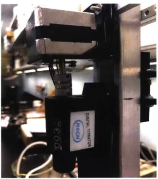
Titrator:
The Hack alkalinity test kit comes with a digital titrator which is basically a hand-held precision syringe pump. Rotating the dial presses the plunger on the sulfuric acid cartridge to deliver small measured amounts of acid during the titration process. The amount of fluid dispensed is indicated by a rotary mechanical counter. To achieve the system's goal of automation, this digital titrator was modified by removing the knob at the back of the device and coupling it to the stepper motor through a shaft coupling.
- Stepper motor
After testing, turning 36 degrees will lead I digit of titration. So, the 4-wire bipolar step motor is set with 200 steps per revolution and 20 steps for each time of titration. ("Adafruit Industries", 2019)
Delivery: 800 digits/mL or 0.00 125 mL/digit Accuracy: 1% for readings over 100 digits.
("Hach USA", 2019)
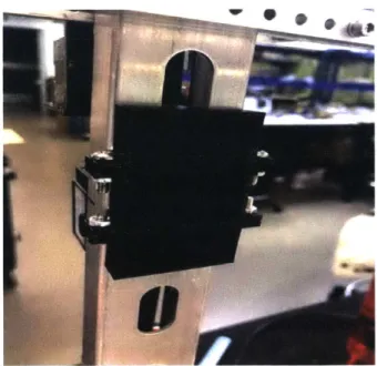
- Modification of the Digital Titrator
The back cover has been removed, so the digital titrator could be able to be coupling
with step motor. Theses imagine below is the method and the result of modification on
HACH digital titrator.
Unmodified set up:
Figure 5 Unmodified digital litrator. From right to left, titrator dial, digital counter, titrator body, sulfuric acid cartridge and " " shaped delivery tube.
Modified titrator:
K..
Figure 7 Titrator connected to stepper mnotor through shaft coupling
- Shaft coupling
Cuts in the coupling body allow flexibility to handle parallel, axial, and angular misalignment. The shaft coupling allows zero backlash (no play) and do not need lubrication. The material is lightweight, corrosion-resistant aluminum and are also known as helical beam couplings.
-
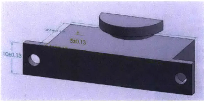
Holder
Holders for digital titrator have to be designed and 3D printed for the perfect fit with framing components. The imagines below are draw from Solidworks. Units are in millimeters, and these holes are using for assembling with screw and nuts.
Figure 8 Back view of holders Y
t-x
aL
,t%
x 'rbotc*Figure 9 Assembly view of holders
4 NJ X W -Wj I IT' 1 0 m , L.J
Figure 10 Top part
The bulge is used to fix holder with farming structure.
Figure I I Middle part
The bulge of this part could immobilize the digital titrator.
Figure 12 Bottom part
The sunken part is used to hook up with the hump of digital titrator.
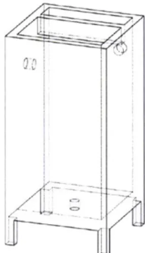
- Test chamber (180ml)
There is a 3D-printed cube test chamber used in the measuring system. There are sensor
holder, input hole, output hold, and emergency leaking hole printed with the test
chamber.
Figure 13 Test chamber
Motors:
-
Liquid pump
A small gear pump driven by a brushed DC motor is used to fill the test chamber with
a water sample. The pump's operating voltage is 12VDC, the maximum flow rate is
2.5L/M, and maximum pressure is 3 Bar (Trossen Robotics, Model TI-TG-02B-DC12B).
- Solenoid valve
This solenoid valve is
1-way,
2-position, and normally closed valve, suitable for gas and liquid. Its exhaust speed is less than 3 seconds (time to reduce air pressure from 300 mmHg to 15 mmHg in 500CC tank). ("Aliexpress", 2019)- Analog Hot Plate/Stirrers
is contributing in the measuring system. The test chamber holds a Teflon-coated
magnetic stir bar.
Software:
The functions of the system are including user interface (LED, Start/pause button), test
chamber and tubing washing, pH measurement and titration, calculation, data logging
(Micro SD card), and data logging and plotting (excel)
To plot the line chart of pH value and number of drops in titration, the PLX DAQ v2
has been used in the system. It is a program used to establish an easy communication
between Microsoft Excel on a Windows Computer and any device that supports serial
port protocol. It was intentionally written to allow communication between Arduino
and Excel. The program uses two parts to work: the special Microsoft Excel
Spreadsheet with the PLX DAQ v2 UI (Figure 14) and commands plus any Arduino
device that sends special commands for communication. (Devil, N., 2016)
PLX-DAQ for Excel "Version 2" by NetADevil
Control v- - Rogincomin data? P Add Amestwmp
PLX-DQ Atr c. .. .1 P
dog outio data? W Log stnsb messages'
P Custom Checkbox 2
Settings
r
Custmc dhedihbx3POrt 4 P Reset on Connect
BMI&1 60 Reset Tuner
Sheet gumne ti post tiz Simple Data '
(feisnd arteir re..inng)
Controller Messages
Disconnected
Do not mme tHis wmdow around while bmgiq I
That might crash Excel'
Functions of LX DAQ buttons:
* Port: set to Arduino port (same as in Arduino IDE => Tools => Port, e.g., 4 for
COM4
* Baud: set to the baud rate you run your Arduino on (e.g., 9600 in the automatic system, the Arduino code using Serial.begin(9600);)
* Connect: connects to Arduino and starts logging
* Pause logging/resume logging: when connected will pause the logging of data * Reset Timer: will set the Timer to 0. The Timer can be used to measure how
long Excel is already logging
* Clear Columns: will delete all logged data from the sheet. Won't clear the labels of the columns
* Display/Hide direct debug: will show or hide the text field on the right. The Direct Debug Window can be used to manually monitor commands received by PLX DAQ v2 in Excel
* Sheet name to post to: this will list all sheets in the Excel workbook. The logged data will be posted to the selected sheet in the dropdown. This sheet will be referred to as the "ActiveSheet" throughout this document.
* Controller Messages: in the field below the most recent commands and status information will be shown. Most likely the information is changing way too fast for users to read, thus use the Direct Debug Window
* Reset on Connect: the checkbox should be ticked at all time. If tick the first command from Excel to Arduino will be to restart, thus the users code starts from the beginning as well. This way the users can have a fresh session to connect to the Arduino without restarting it.
* Custom Checkbox 1/2/3: these can be used to control the system during run in any way the users want. There are commands to label the Checkboxes by Arduino and to query the state of the boxes. Users could for example label one box "Measure pH as well?" and check on demand in Excel if users want to set the Arduino to measure pH with a second sensor next to only measure e.g., temperature. There are special commands Arduino can use to query the status of the checkboxes.
* Log incoming data? checkbox: information received from Arduino will be displayed in the direct debug window.
* Log outgoing data? checkbox: information send to your Arduino will be displayed in the direct debug window.
* Log system messages? checkbox: information from Excel will be display in the direct debug window (e.g., errors).
* Add timestamp? checkbox: will add a timestamp to every information logged
in the direct debug window. This is handy for debugging.
= =>: will go to the next page of the direct debug window.
* <=: will go to the front page of the direct debug window. * Clear: will clear all information in the direct debug window
The data types of the automatic measurement including real date, real time, measuring time, number of titration digits, pH value, temperature, and digits/pH line chart (as shown on Figure 15)
Dote 5/2019 5212019 5W2/2019 512/2019 5212019 5212019 51212019 52/2019 512/2019 512/2019 522019 512/2019 52/2019 12/2019 5/2/2019 512/2019 522019 512/2019 51212019 5/2/2019 52/2019
Figure 15 Test data in Excel
Overall Function of system (Arduino) Software:
*
Figure 16 Working loop in Arduino code
Detailed Explanation of Software Function:
1. Test SD card i
2. Test real time function -4
28
Time 4:37:13 AM 4:37:14 AM 4:37:15 AM 4:37:17 AM 4:37:18 AM 4:37:20 AM 4:37:21 AM 4:37:22 AM 4:37:24 AM 4:37:25 AM 4:37:26 AM 4:37:28 AM 437:29 AM 4:37:30 AM 4:40:14 AM 4:40:16 AM 4:40:17 AM 4:40:18 AM 4:40:20 AM 4:40:21 AM 4:40:23-AM Timwr 442.288100 443.637700 445.038100 446.38900 447.739300 449.040000 450.409200 451.825200 453.108400 454.465800 455.842800 457.200200 458.536100 459.911100 623.942400 625.305700 826.868900 628.043900 629.356400 630.706000 -532.106400 Drops 22 23 24 25 26 27 28 29 30 31 32 33 34 35 0 1 2 3 4 5 pH T___U pPNtur0-8.26 I.K 8.2 PLX-DAC ' -8.12 8.03 Cntrl v. 2.11 7.93 F cust~ne ftex -a 7.83 F Autm Chsedbox 2 7.19 Cusbwn Chod.b-6.82 pr 4 Reset on Connect 6.53 os*Tbw 6.1 5.43 nt me NIVINS 5.014.75 Displpr drott deb-Ig
o-4.56
9.21 Sheet namte pat t: Sop* Data
9.21 (MiN Aser nnd 9.21 Contirodler H 9.22 9.21 sms 9.22 9.22 linity test 20 22 2. 26 2S1
1-*
3. Clear data in excel i
4. Wait for users to push button: this is the Start/pause button. Measurement will not start until the switch turned on. While the system is working, the light will keep lighting -i
5. Starting loop i
6. Wash the test chamber -z. 7. Sample liquid in -i
8. Stop and measurement (temperature and pH value) i
9. Data login: Date, Real time, Temperature, and PH value will be labeled and log into both excel table and micro storage card.
-10. Titration to pH valve equal to 8.3: there is a pH measurement after every single digit of titration. Date, Real time, Working time, Temperature, Number of digits, and PH value will be log into excel. Digits/PH value will be plotting during date logging -i
11. Get Phenolphthalein Alkalinity i
12. Titration until endpoint: data logging and plotting will execute as above -13. Calculation different kinds of alkalinity (Hydroxide, Carbonate, and
Bicarbonate)
-14. Data login: current liquid level, number of digits, the amount of Phenolphthalein, and Total alkalinity, as well as different kinds of alkalinity will be log into micro SD card
-15. Reset -End loop -4
Working flow:
The Working flow of the automatic measuring system is programmed as follow.
% S
I
'I
i
'I
'I
I
"p
Figure 17 Arduino Working Flow
30
I I
Detailed Operation (steps are from Figure 17)
Step 3: Before the start of measurement and titration, Arduino will control the input pump and solenoid valve to fill up and drain out the test chamber three time to wash it.
Step 4: While sample liquid excess warning line. A warning will be displayed, input pump will be stopped, and solenoid valve will be open.
Step 5: Real time, Temperature, pH value will be measured and write into both SD card and Excel.
Step 6: Titrate to two endpoints, phenolphthalein alkalinity and total alkalinity will be recorded. During the titration, number of drops and testing time will be recorded into Excel.
Step 7: Calculate and store the amount of hydroxide alkalinity, carbonate alkalinity, and bicarbonate alkalinity.
Tests and Results:
- Outcomes and compares
The line chart below shows the results of three consecutive alkalinity tests for tap water. The concentration of alkalinity in sample water is around 35 mg/L. Different temperature will lead different results, so it is important to make comparisons at similar temperatures. During the preparation part of the cycle (reset system, check working state of hardware, and wash test chamber), the stir plate was turned off manually to minimize the influence from leaking acid and to prevent damage to the sensors and the
"J" tube caused by the spin bar spinning in air.
Compare with the manual measurement for tap water (Table 1), the accuracy of
auto-test system is around 15% (total alkalinity). The most significant difference between
auto and manual tests is the amount of Phenolphthalein Alkalinity.
Table I Test results
Results pH Drops P. Alk. Total Alk. TEMP.
First Test 9.21 35 22 35 25.92 Second Test 9.15 36 22 36 25.92 Third Test 9.15 33 19 33 25.92 Manual 9.30 30 4 30 26.03 with color changes 32
Results line chart:
Alkalinity Test
109 -- 8810"
:
ia
8 Mc7 6 5 4 1 3 5 7 9 11 13 15 17 19 21 23 25 27 29 31 33 35 37 Drops First endpoint, pH=8.3 - F irst test -.- Second test --- Third test -- Seond endpoint, pH=4.6Figure 18 PH/drops line chart
Table 2 Relationship between second endpoints and alkalinity
Sample Composition
Second End Point
Alkalinity about 30 mg/L
pH 4.9
Alkalinity about 150 mg/L
pH 4.6
Alkalinity about 500 mg/L
pH 4.3
Silicates or Phosphates present
pH
4.5
Industrial waste or complex system
pH
4.5
- Data analysis
The reason of the big difference on Phenolphthalein Alkalinity might due to the different mixing efficiency. The stir plate was being used on both automatic test and
manual test. But, instead of the test chamber in the automatic system, the manual test used an Erlenmeyer flask which permitted more efficient, continuous stirring and mixing of the acid with sample liquid. Furthermore, the automatic system was set to titrate and measure in less than 2 second for each drop of acid, but the manual test allowed much more time than this. It seems like the total alkalinity/drops from automatic system should be much higher, similar to the manual test's Phenolphthalein Alkalinity. There are several possible reasons for this result. 1) There was acid leaking during the automatic testing. This would lead to less drops of total alkalinity in automatic system, but it should also cause a lower total alkalinity number as well and this did not happen. 2) The stir plate was on continuously during the manual test, but it was stopped during the preparation section of automatic test. Thus, each automatic test started with the fluid at rest and it took some time to speed-up and thoroughly mix the fluids. Because of inefficient mixing more drops of acid needed to be added for the initial pH step that determines Phenolphthalein alkalinity. Later during the automatic test, when the fluid was at maximum velocity and mixing was most effective fewer drops of acid were needed to accomplish the second pH endpoint. In this way the Phenolphthalein alkalinity was lower than the manual test, but the overall volume of acid added was the same as the total alkalinities matched. 3. The second end point is different. The second end point in automatic system is set as pH = 4.6 (Table 2) to match its premier goal of measure sea water. But the Bromocresol Green-Methyl Red indicator will change its color to light pink while pH less than 4.5. Consider the human eyes error, the final pH in manual test might be even lower than 4.5 (this will lead more drops of total alkalinity in manual test).
- Design analysis
The vibration of step motor and stir particular, as well as water flow inside of the test chamber might cause sulfuric acid to leak from the titration cartridge. This would lead to inaccurate results of relative lower alkalinity. Changing the design of the testing chamber to better isolate the spin bar from the sensors and acid tube would eliminate this problem.
To improve the accuracy of the automatic measuring system, the pH sensor needs more time to give accurate measurement. And the stir efficiency should also be improved, redesign a new shape of test chamber instead of this cubic one might be a good way. Or, speed of measurement might have to be sacrificed to avoid this inaccuracy. The current testing time is around 200 seconds for each test, this includes around 150 seconds for prepare section and 50 seconds of testing section.
Conclusion:
The major contribution of this work is the development of a low-cost alkalinity sensing system that has the potential of being deployed in great numbers in the ocean to support studies of ocean acidification and its environmental impacts. The bench-top prototype demonstrated the basic autonomous functions of the system: sample filling, measurement, calculation, data logging, sample removal and system cleaning. Following further development to improve the system's performance as outlined above, the stage will set the stage for the packaging of the device into a field-deployable instrument.
References :
- "Aliexpress", (2019) "Mini Solenoid Valve Normal Close AJK-F 12A0504", aliexpress.com. [Online]. Available:
https://www.aliexpress.com/item/Mini-Solenoid-Valve-Normal-Close- I 2V-AJK-F12A0504/32266431017.html. [Accessed: 09- May- 2019].
- "Adafruit Industries", (2019) "Adafruit Assembled Data Logging shield for
Arduino", Adafruit.com. [Online]. Available:
https://www.adafruit.com/product/ 141. [Accessed: 08- May- 2019]. - "Adafruit Industries", (2019) "Arduino Mega 2560 R3 (Atmega2560
-assembled)", A dafruit.com. [Online]. Available:
https://www.adafruit.com/product/191. [Accessed: 08- May- 2019]. - "Adafruit Industries", (2019) "Adafruit Motor/Stepper/Servo Shield for
Arduino v2 Kit", Adafruit.com. [Online]. Available:
https://www.adafruit.com/product/1438. [Accessed: 1 1- May- 2019].
- "Adafruit Industries", (2019) "Stepper motor -NEMA-17 size -200 steps/rev, 12V 350mA", Adafruit.com. [Online]. Available:
https://www.adafruit.com/product/324. [Accessed: 08- May- 2019]. - "Atlas Scientific", (2019) "EZO pH Circuit
I
Atlas Scientific",Atlas-scientific.com. [Online]. Available:
https://www.atlas-scientific.com/product-pages/circuits/ezoph.html. [Accessed: 08-
May-20 19].
- "Atlas Scientific", (2019) "EZO RTD Temperature Circuit I Atlas
Scientific", Atlas-scientific.com. [Online]. Available:
https://www.atlas-scientific.com/productpages/circuits/ezortd.html. [Accessed: 11-
May-2019].
- Bellerby, R.G.J., D.R. Turner, G.E. Millward, and P.J. Worsfold. (1995). Shipboard flow injection determination of sea water pH with
spectrophotometric detection. Analytica Chimica Acta 309:259-270, http://dx.doi.org/10. 1016/0003-2670(95)00054-4.
- Carter, B., J. Radich, H. Doyle, and A. Dickson. (2013). An automated system for spectrophotometric seawater pH measurements. Limnology and
Oceanography Methods I 1(1):16-27, http://dx.doi.org/10.4319/lom.2013.11.16.
- "Corning", (2019) "Corning* PC-220 Analog Hot Plate/Stirrers",
Ecatalog.corning.com. [Online]. Available:
https://ecatalog.corning.com/life- sciences/b2c/US/en/Equipment/Constant-Temperature-Equipment/Hot-Plate-Stirrers/Corn ing%C2%A
E-PC-220-Analog-Hot-Plate-Stirrers/p/corningPC220HotPlateStirrers. [Accessed: 08- May- 2019]. - Consi, T. (2019) Introduction to Arduino programming. MIT subject 2.017
lecture notes.
- Davis, C. (2018) Reconstructing Aragonite Saturation State Based on an
Empirical Relationship for Northern California. 201 8.
- Devil, N. (2016) PLX-DA
Q,
2nd ed.- Dickson, A. (2007) Guide to Best Practices for Ocean C02 Measurenenls. North Pacific Marine Science Organization.
- Gledh ill, D. (2015) Ocean and Coastal Acidification off New England and
Nova Scotia.
- "Hach USA", (2019) "Digital Titrator I Hach USA -Overview", Hach.com. [Online]. Available:
https://www.hach.com/digital-titrator/product?id=7640447369#. [Accessed: 08- May- 2019].
- Hillborn, E. (1983) Probe
for
In Situ Measurement ofAlkalinity and pH inNatural Waters. pp. 180-1182.
- "Li-Cor", (2019) "Measuring pCO2 and Dissolved Inorganic Carbonates in
Water", Licor.com. [Online]. Available:
https://www.licor.coin/documents/l zgpt3yrjgsfublefqne. [Accessed: 09-
May-20 19].
- Martz, T. (2015) TECHNOLOGY FOR OCEAN ACIDIFICATION
RESEARCH. 2015.
- McLaughlin, K. (2015) Core Principles of the California Current
Acidification Network. Oceanography, 2015.
- "McMaster-Carr", (2019) Mcmaster.comn. [Online]. Available:
https://www.-ncmaster.com/shaft-couplings. [Accessed: 08- May- 2019].
- "MILONE Technologies", (2019) "Chemical eTape@
assembly", Milonetech.com. [Online]. Available:
https://milonetech.com/products/chemical-etape-assembly. [Accessed: 08-May- 2019].
- Oram, B. (2014) "Water Research Center - Alkalinity and Stream Water
Quality", Water-research.net. [Online]. Available:
https://www.water-research.net/index.php/the-role-of-alkalinity-citizen-monitoring. [Accessed:
10- May- 2019].
- "ServoCity", (2019) "1010 Series T-Slotted Extrusion
80/20@", Servocity.com. [Online]. Available:
https://www.servocity.com/1 010-series-t-slotted-extrusion-80-20r. [Accessed:
08- May- 2019].
- Spaulding, R. et al., (2019) "Autonomous in Situ Measurements of Seawater
Alkalinity", Environmental Science & Technology.
- "University of Massachusetts", (2019) "Analysis Method for pH and Alkalinity", Water Resources Research Center. [Online]. Available:
- "Whiteboxes", (2019) "Tentacle Mini for Arduino - Whitebox
Labs", Whiteboxes.ch, 2019. [Online]. Available:
https://www.whiteboxes.ch/shop/tentacle-mini/?v=75]6fd43adaa. [Accessed:
08- May- 2019].
- "Wikipedia", (2019) "Alkalinity", En.wikipedia.org, 2019. [Online].
Available: https://en.wikipedia.org/wiki/Alkalinity#cite-note-2. [Accessed:
10- May- 2019].
List of companies
" Aliexpress, https://www.aliexpress.com
* Adafruit Industries, NEW YORK, NY, USA. https://www.adafruit.com * Atlas Scientific, 43-15 11 th St, Long Island City, NY 11 101, USA.
https://www.atlas-scientific.com
* Corning, One Riverfront Plaza, Corning, NY,14831, USA. https://www.corning.com
" Hach USA, Loveland, Colorado, USA. https://www.hach.com
" Li-Cor, 4647 Superior Street, Lincoln, Nebraska USA. https://www.licor.com
* McMaster-Carr, 200 New Canton Way, Robbinsville, NJ, USA. https://www.mcmaster.com/
* MILONE Technologies, 17 Ravenswood Way
I
Sewell, NJ, USA. https://milonetech.com* ServoCity, 3850 East 12th Avenue, Winfield, KS, USA. https://www.servocity.com
* Whiteboxes Labs, Meister Whiteboxes GmbH, Solothurnerstrasse 19, CH-4053, Basel, Switzerland. https://www.whiteboxes.ch
Appendix A: Arduino Source Code
#include <Wire.h> // enable 12C.
#include "RTClib.h" #include <SPI.h> #include <SD.h>
#define TOTAL _CIRCUITS 2 /set how many 12C circuits are attached to the Tentacle #define address 102 //default 12C ID number for EZO RTD Circuit.
#include <AdafruitMotorShield.h>
RTCPCF8523 rtc; /real time clock int i = 0;
int w = 0; /counter to wash test chamber
const unsigned int baudhost = 9600; // set baud rate for host serial monitor(pc/mac/other) const unsigned int send readingsevery 100; // set at what intervals the readings are sent to the
computer (NOTE: this is not the frequency of taking the readings!) unsigned long nextserial time;
char daysOfTheWeek[7][12] = {"Sunday", "Monday", "Tuesday", "Wednesday", "Thursday", "Friday", "Saturday"};
float TEMPreading; /save temperature data
float level-float; //float var used to hold the float value of the liquid level sensor.
String levelString = ""; /data from liquid level sensor
char sensordata[30]; /7 A 30 byte character array to hold incoming data from the sensors byte sensor bytes received = 0; /7 We need to know how many characters bytes have been received
byte code = 0; // used to hold the 12C response code.
char TEMPdata[20]; /we make a 20 byte character array to hold incoming data from the RTD circuit.
byte in char = 0; // used as a I byte buffer to store in bound bytes from the 12C Circuit. int time = 1000; /used to change the delay needed depending on the command sent to the EZO Class RTD Circuit.
float tmp float; //float var used to hold the float value of the RTD. int d = 0; /counter used drops for titrator.
byte p = 0; /amount of Phenolphthalein Alkalinity.
float Talk = 0; //Total alkalinity
float Palk = 0; //Phenolphthalein Alkalinity
char ph data[20]; //we make a 20-byte character array to hold incoming data from the pH circuit. float phfloat; //float var used to hold the float value of the pH.
int channel_ids[] = {102, 99}; /A list of 12C ids.
char *channel names[] = {"TEMP", "PH"}; /A list of channel names (must be the same order as in
channel-ids[]) -only used to designate the readings in serial communications
String readings[TOTAL _CIRCUITS]; // an array of strings to hold the readings of each channel
int channel = 0; // INT pointer to hold the current position in the
channelids/channelnames array
const unsigned int reading delay = 1000; /time to wait for the circuit to process a read command. datasheets say I second.
unsigned long next readingtime; / holds the time when the next reading should be ready from the circuit
boolean request pending - false; // wether or not we're waiting for a reading const unsigned int blinkfrequency
unsigned long next blink time;
250; // the frequency of the led blinking, in milliseconds // holds the next time the led should change state
int lightstate = LOW; // keeps track of the current led state const int chipSelect = 10;
const int led = 7;
const int Button = 6;
int a= 1;
int previous = LOW;
// Create the motor shield object with the default 12C address AdafruitMotorShield AFMS = Adafruit_ MotorShieldo;
// Or, create it with a different 12C address (say for stacking)
// AdafruitMotorShield AFMS = AdafruitMotorShield(0x61); // Connect a stepper motor with 200 steps per revolution (1.8 degree) // to motor port #1 (M I and M2)
Adafruit StepperMotor *myStepper = AFMS.getStepper(200, 2);
AdafruitDCMotor *myMotorl = AFMS.getMotor(2);
AdafruitDCMotor *myMotor2 = AFMS.getMotor(l);
void setup() {
levelString = analogRead(A2); //liquid level sensor
pinMode(led, OUTPUT); // set the led output pin
pinMode(Button, INPUT); // set the button iutput pin Serial.begin(baud host); // Set the hardware serial port.
Wire.begin(); // enable 12C port.
nextserialtime = millis() + sendreadings every; // calculate the next point in time we should do serial communications
while (!Serial) {
; wait for serial port to connect. Needed for native USB port only
}
Serial.print("Initializing SD card..."); if (!SD.begin(chipSelect)) {
Serial.println("Card failed, or not present");
// don't do anything more:
while (1); } if (! rtc.begino) { Serial.println("Couldn't find RTC"); while (1); } if (! rtc.initializedO) {
Serial.printin("RTC is NOT running!");
// following line sets the RTC to the date & time this sketch was compiled
rtc.adjust(DateTime(F(_DATE_), F(__TIME_)));
}
Serial.println("card initialized.");
AFMS.begino; // create with the default frequency 1.6KHz myStepper->setSpeed( 10); ! 10 rpm
myMotor I ->setSpeed(50); myMotorl ->run(RELEASE); myMotor2->setSpeed(400); myMotor2->run(RELEASE);
/for data analysing
//Serial.printin("CLEARDATA"); // clears sheet starting at row 2 Serial.println("CLEA RSH EET"); // clears sheet starting at row I // define 5 columns named "Date", "Time", "Timer" "Drops", and "pH" Serial.println("LABEL,Date,Time,Timer,Drops,pH,Temperature");
Serial.println("CUSTOMBOX3,LABEL,Auto Save?"); Serial.println("CUSTOMBOX3,SET, I "); } void loop() { do switcho; if(lightstate == HIGH) { dosampleliquido; do serial();
}
}
void do _switch() { if (digitalRead(Button) == LOW) {lightstate = ! lightstate; // this changes it to LOW if it was HIGH, and to HIGH if it was LOW delay( 100); i digitalWrite(led, lightstate); I void dosampleliquid() { do washo; while (analogRead(A2) <= 566) { myMotor I->run(FORWARD); myMotor I ->setSpeed(80); myMotor2->run(FORWARD); myMotor2->setSpeed(0);
}
myMotor I ->setSpeed(0); while (analogRead(A2) >= 590) {Serial.println("Too much liquid"); myMotor I->setSpeed(0); myMotor2->setSpeed(400);
}
myMotor2->setSpeed(0);
Serial.println("1 00ml of sample liquid");
void dowash() {
for (int w = 0; w < 4; w++) {
Serial.println("test chamber washing"); while (analogRead(A2) <= 568) { myMotor2->run(FOR WARD); myMotor2->setSpeed(0); myMotorl ->run(FORWARD); myMotor I->setSpeed(70);
}
myMotorI ->run(FORWARD); myMotori ->setSpeed(0); myMotor2->run(FORWARD); myMotor2->setSpeed(400); delay(28000);}
myMotor2->run(FORWARD); myMotor2->setSpeed(0);//while no enough liquid //turn on the input pump //turn off the solenoid valve
//print warning
//turn off the input pump while emergency //turn on the solenoid valve while emergency
//wash 3 times
//turn off the solenoid valve //turn on the input pump
//turn off the input pump //turn on the solenoid valve
//turn off the input pump
// do serial communication in a "asynchronous" way
void do serial() {
DateTime now = rtc.nowo; //set real time
if (millisO >= nextserial time) { // is it time for the next serial communication? if (i < TOTALCIRCUITS) { if (i == 0) { //temperature sensor request readingo; receivereading(); TEMPreading = readings[i].toFloat(;
Serial.print(channelnames[i]); // print channel name Serial.print(":\t");
Serial.println(readings[i]); // print the actual reading
File dataFile = SD.open("Alkalinity Measurement txt", FILEWRITE);//write data into SD card if (dataFile) { dataFile.print(now.year(, DEC); dataFile.print('/'); dataFile.print(now.montho, DEC); dataFile.print('/'); dataFile.print(now.day(, DEC); dataFile.print(" ("); dataFile.print(daysOfheWeek[now.dayOfTheWeek(]); dataFile.print(") "); dataFile.print(now.houro, DEC); dataFile.print(':'); dataFile.print(now.minute(), DEC); dataFile.print(':'); dataFile.print(now.secondo, DEC); dataFile.printino; dataFile.print(channelnames[i]); dataFile.print(":\t"); dataFile.println(readings[i]); dataFile.close(; if (readings[i].toFloat() > 0) { i= 1; //change to pH sensor } doserial();
}
if (i == 1) { //pH sensor if (readings[i].toFloat() > 0) { while (readings[i].toFloat( > 8.30) { dotitration(;}
p =(d); Palk = p; Serial.print("Phenolphthalein Alkalinity:"); Serial.println(Palk); while (readings[i].toFloato > 4.6) { dotitrationO; I Talk = (d);Serial.println( (String) "DATA,DATE,TIME,TIMER," + d + "," + readings[i].toFloat() + "," +
TEMPreading + ",AUTOSCROLL _20" );
Serial.println("END Test And SAVE Results"); Serial.printin("CUSTOMBOX3,GET"); if (Serial.readString Until( I 0).toInt() {
Serial.println("SAVE WORKIBOOKA S,AkalinityTest");
I
else {
Serial.println("Can't Save Excel");
I
Serial.print("pH after testing:"); Serial.println(readings[i]);
Serial.print("Phenolphthalein Alkalinity:"); Serial.println(Palk); Serial.print("Total Alkalinity:"); Serial.println(Talk); docalculationo; Serial.print("Liquid level:"); Serial.println(analogRead(A2)); i =0; d =0; lightstate = LOW; dosampleliquido;
}
else { delay(3000); dosensorreadings(); doserial();}
}
else { i =0;
Inextserial time = millis() + send readingsevery;
}
}
else {
Serial.print("Liquid not enough"); dosampleliquido;
}
}
void docalculation() { if (Palk == 0) {
File dataFile = SD.open("Alkalinity Measurement.txt", FILEWRITE); if (dataFile) { dataFile.printin("Hydroxide Alkalinity:Orng/L"); dataFile.println("Carbonate Alkalinity:Omg/L"); dataFile.print("Bicarbonate Alkalinity:"); dataFile.print(Talk); dataFile.println("mg/L"); dataFile.closeo;
}
}
else { Palk = Palk * 2.00; if (Palk < Talk) {File dataFile = SD.open("Alkalinity Measurement.txt", FILE_WRITE); if (dataFile) {
dataFile.println("Hydroxide Alkalinity:Omg/L"); dataFile.print("Carbonate Alkalinity:");
dataFile.print(Palk); dataFile.println("mg/L");
dataFile.print( "Bicarbonate Alkalinity:"); dataFile.print(Talk -Palk);
dataFile.println("mg/L"); dataFile.close(;
}
if (dataFile) { dataFile.println("Hydroxide Alkalinity:Omg/L"); dataFile.print("Carbonate Alkalinity:"); dataFile.print(Talk); dataFile.println("mg/L"); dataFile.printin("Bicarbonate Alkalinity:Omg/L"); dataFile.closeo;
}
}
if (Palk > Talk) {File dataFile = SD.open("Alkalinity Measurement.txt", FILEWRITE); if (dataFile) { dataFile.print("Hydroxide Alkalinity:"); dataFile.print(Palk -Talk); dataFile.println("mg/L"); dataFile.print("Carbonate Alkalinity:"); dataFile.print(Talk -(Palk / 2.00)); dataFile.println("mg/L"); dataFile.printin("Bicarbonate Alkalinity:Omg/L"); dataFile.closeo;
}
}
}
}
void do titrationo {Serial.println( (String) "DATA,DATE,TIME,TI MER," + d + "," + readings[i].toFloat() + "," +
TEMPreading + ",AUTOSCROL L_20");
if (analogRead(A2) >= 560) {
myStepper->step(20, FORWARD, DOUBLE);
d=d+ 1;
}
request readingo; receive readingo;
}
// take sensor readings in a "asynchronous" way
void dosensorreadings() {
if (request pending) { // is a request pending?
if (millis() >= next reading time) { // is it time for the reading to be taken?
receive readingo; // do the actual 12C communication
}
} else { // no request is pending,
channel = (channel + I) % TOTA L_CIRCUITS; // switch to the next channel (increase current
channel by 1, and roll over if we're at the last channel using the % modulo operator)
request readingo; // do the actual 12C communication
}
}
// Request a reading from the current channel void request readingo {
requestpending = true;
Wire.beginTransmission(channelids[channel]); // call the circuit by its ID number. Wire.write('r'); // request a reading by sending 'r'
W ire.endTransmission(); // end the 12C data transmission.
next_readingtime = millis() + readingdelay; // calculate the next time to request a reading delay( 1000);
}
// Receive data from the 12C bus
void receivereading() {
sensor bytes_received = 0; // reset data counter
memset(sensordata, 0, sizeof(sensordata)); // clear sensordata array;
Wire.requestFrom(channelids[channel], 48, 1); // call the circuit and request 48 bytes (this is more then we need).
code = Wire.read(; while (Wire.available() {
in-char = Wire.read(;
// are there bytes to receive?
// receive a byte.
if (in char == 0) { // if we see that we have been sent a null command.
Wire.endTransmission(; // end the 12C data transmission.
break; // exit the while loop, we're done here
}
else {
sensordata[sensor bytesreceived] = in_char; // load this byte into our array. sensorbytesreceived++;
}
}
switch (code) { case 1: readings[channel] break; case 2: readings[channel] break; case 254: readings[channel] break; case 255: readings[channel] break; } request pending = fa}
// switch case based on what the response code is.
// decimal I means the command was successful.
= sensordata;
// exits the switch case.
/ decimal 2 means the command has failed.
= "error: command failed";
// exits the switch case.
// decimal 254 means the command has not yet been finished calculating.
= "reading not ready"; // exits the switch case.
// decimal 255 means there is no further data to send.
= "error: no data";
// exits the switch case.