Publisher’s version / Version de l'éditeur:
40th Review of Progress in Quantitative Nondestructive Evaluation: Incorporating
the 10th International Conference on Barkhausen Noise and Micromagnetic
Testing, pp. 405-411, 2014-02-18
READ THESE TERMS AND CONDITIONS CAREFULLY BEFORE USING THIS WEBSITE.
https://nrc-publications.canada.ca/eng/copyright
Vous avez des questions? Nous pouvons vous aider. Pour communiquer directement avec un auteur, consultez la
première page de la revue dans laquelle son article a été publié afin de trouver ses coordonnées. Si vous n’arrivez pas à les repérer, communiquez avec nous à PublicationsArchive-ArchivesPublications@nrc-cnrc.gc.ca.
Questions? Contact the NRC Publications Archive team at
PublicationsArchive-ArchivesPublications@nrc-cnrc.gc.ca. If you wish to email the authors directly, please see the first page of the publication for their contact information.
NRC Publications Archive
Archives des publications du CNRC
This publication could be one of several versions: author’s original, accepted manuscript or the publisher’s version. / La version de cette publication peut être l’une des suivantes : la version prépublication de l’auteur, la version acceptée du manuscrit ou la version de l’éditeur.
For the publisher’s version, please access the DOI link below./ Pour consulter la version de l’éditeur, utilisez le lien DOI ci-dessous.
https://doi.org/10.1063/1.4864848
Access and use of this website and the material on it are subject to the Terms and Conditions set forth at
Laser-ultrasonic inspection of hybrid laser-arc welded HSLA-65 steel
Lévesque, D.; Rousseau, G.; Wanjara, P.; Cao, X.; Monchalin, J.-P.
https://publications-cnrc.canada.ca/fra/droits
L’accès à ce site Web et l’utilisation de son contenu sont assujettis aux conditions présentées dans le site LISEZ CES CONDITIONS ATTENTIVEMENT AVANT D’UTILISER CE SITE WEB.
NRC Publications Record / Notice d'Archives des publications de CNRC:
https://nrc-publications.canada.ca/eng/view/object/?id=d6bd12fb-ee35-4870-a268-56947d47c6a3 https://publications-cnrc.canada.ca/fra/voir/objet/?id=d6bd12fb-ee35-4870-a268-56947d47c6a3Laser-Ultrasonic Inspection of Hybrid Laser-Arc Welded
HSLA-65 Steel
D. Lévesque
a, G. Rousseau
a, P. Wanjara
b, X. Cao
b, and J.-P. Monchalin
a aNational Research Council Canada, Boucherville, Qc, CanadabNational Research Council Canada, Montreal, Qc, Canada
Abstract. The hybrid laser-arc welding (HLAW) process is a relatively low heat input joining technology that combines the synergistic qualities of both the high energy density laser beam for deep penetration and the arc for wide fit-up gap tolerance. This process is especially suitable for the shipbuilding industry where thick-gauge section, long steel plates have been widely used in a butt joint configuration. In this study, preliminary exploration was carried out to detect and visualize the welding defects using laser ultrasonics combined with the synthetic aperture focusing technique (SAFT). Results obtained on 9.3 mm thick butt-welded HSLA-65 steel plates indicated that the laser-ultrasonic SAFT inspection technique can successfully detect and visualize the presence of porosity, lack of fusion and internal crack defects. This was further confirmed by X-ray digital radiography and metallography. The results obtained clearly show the potential of using the laser-ultrasonic technology for the automated inspection of hybrid laser-arc welds.
INTRODUCTION
High energy density laser welding can reduce the heat input required for structural assembly through the reduction of inline energy of each pass and the minimization of the number of passes necessary for full penetration of thick plates. This process permits deep penetration welding at high advancing speeds, renders a narrow fusion zone and small heat affected zones (HAZ) in the weldment, as well as reduces the weld distortion that can cause the buckling and warping of large welded structures. As such, laser welded structures can render predictable fit-up in subsequent assembly operations and minimize the necessity for reworking. However, a great disadvantage of the laser welding process is the precise fit-up requirement for the joint geometry that is difficult to meet for the assembly of long products. The application of arc welding with filler metal addition combined with the laser can result in a wider weld bead that improves the tolerance to beam-gap misalignment, whilst maintaining the benefits of the laser welding process as described above [1, 2]. In particular, this emerging technology, termed the hybrid laser-arc welding (HLAW) process, which involves combining both the laser and laser-arc sources in one molten pool, is a promising approach for the automated manufacturing of paneled structures for the shipbuilding industry where long and thick steel plates have been widely used in butt configuration, often with restricted accessibility (one-sided welding). Caccese et al. [3] reported that HLAW of a cruciform geometry had a superior fatigue performance compared to other laser-based and conventional welding processes. The study focused on the weld profile but did not consider the effect of the microstructure on the fatigue performance. Recently the authors have investigated the hybrid laser-arc weldability of high strength low alloy (HSLA) steels grades 65 and 80 and evaluated the microstructural characteristics and mechanical properties [4-7].
The introduction and qualification of emerging joining processes also necessitates the development and application of reliable non-destructive evaluation (NDE) techniques that are appropriate for automated fabrication. However, to date little work has been reported for the NDE inspection of steel assemblies manufactured by HLAW. A recent effort proposed the use of an array eddy current technique for detection and sizing of surface and slightly subsurface (< 2 mm) weld flaws for nuclear applications [8]. Satisfactory results were obtained for defects such as lack of penetration (LOP), weld seam misalignment and shallow underfill. Based on the recent success with friction stir welds [9, 10], laser ultrasonics combined with SAFT was employed to explore the possibility of inspecting internal flaws located deep within the thick gauge section of HLAWed steel plates. Preliminary results obtained on 9.3 mm thick butt-welded HSLA-65 steel plates, as reported here, indicated that the laser-ultrasonic SAFT inspection can successfully detect and visualize the presence of porosity, lack of fusion and internal crack defects. Specifically, the HLAW process in its robotic implementation to manufacture the weld sample is first described. The laser-ultrasonic setup used with the SAFT approach is also briefly reviewed. The results obtained are presented and a comparison with those from X-ray digital radiography and metallographic images is discussed.
HLAW OF HLSA-65 STEEL TEST SAMPLE
The weld test sample used for non-destructive evaluation was a butt joint in HSLA-65 steel that was assembled using the HLAW process. The HSLA-65 steel plate was control rolled and had a nominal composition as given in Table 1. Preparation of the HSLA-65 steel for HLAW involved grinding to remove the corroded and oxidized surfaces, which resulted in a reduction in the plate thickness to approximately 9.3 mm for the weld trial coupons. To fully penetrate the thick steel plates, a joint configuration with a Y-groove was prepared. The bevel angle used was about 30º. The root size was 6 mm and no joint gap at the root was used. HLAW was conducted along the length of the HSLA-65 steel plate coupons that each had dimensions of 400 mm (L) × 480 mm (W) x 9.3 mm (T).
Figure 1a shows schematically the hybrid fiber laser-arc welding system. The laser equipment consists of an IPG Photonics 5 kW continuous wave solid-state Yb-fiber laser (YLR-5000) equipped with an ABB robot. A collimation lens of 150 mm, a focal lens of 250 mm and a fiber diameter of 200 µm were employed to produce a nominal focusing spot diameter of 0.33 mm. The laser beam was positioned on the top surface of the work-piece and calibrated at 5 kW. The welding experiment was conducted at a defocusing distance of -2 mm and the maximum laser power (5 kW) in “laser leading” mode that enabled a maximum welding speed of 1.5 m/min for full penetration. It is noteworthy that the laser head was inclined 5° from the vertical position to avoid any damage to the equipment from laser beam reflection. The filler wire used during welding was AWS ER70S-6 (Table 1) with a diameter of about 1.14 mm (0.045"). The wire feed rate was approximately 14.0 m/min. A DC pulsed Fronius MAG arc was placed on the work-piece top surface with a distance of 2 mm from the laser beam. The angle between the electrode axis and the work-piece surface was 55°. To protect the molten weld pool during welding, the top surface of the work-piece was shielded using a mixture of 96% Ar and 4% O2 that was fed through a MAG nozzle at a flow rate of 23.6 L/min (50 cfh), while the bottom surface was shielded using a mixture of 50% He and 50% Ar at a flow rate of 9.44 L/min (20 cfh). The arc current used was 328 A and the voltage is 24.3 V, leading to an arc power of 8.0 kW. A photo of the weld test sample fabricated is shown in Fig. 1b.
TABLE (1). Chemical composition (wt. %) of HSLA-65 plate and AWS ER70S-6 electrode.
C Mn Si Ni Cr Cu Mo Ti N S
HSLA-65 0.1 1.1-1.65 0.1-0.4 0.4 0.2 0.35 0.08 0.007-0.020 0.012 0.01
ER70S-6 0.09 1.4 0.95 0.034 0.022 0.006 0.013
a) b)
FIGURE 1. a) Schematic diagram of the HLAW system and b) the welded test sample.
5° 35° Welding direction Laser GMAW (MAG) Fusion zone Keyhole Melted
zone 2mm Backing gas feeder
Electrode
FIGURE 2. Concatenated X-ray images of the sample. Numbers represent the approximate position from the center of the weld sample (in mm).
a) b)
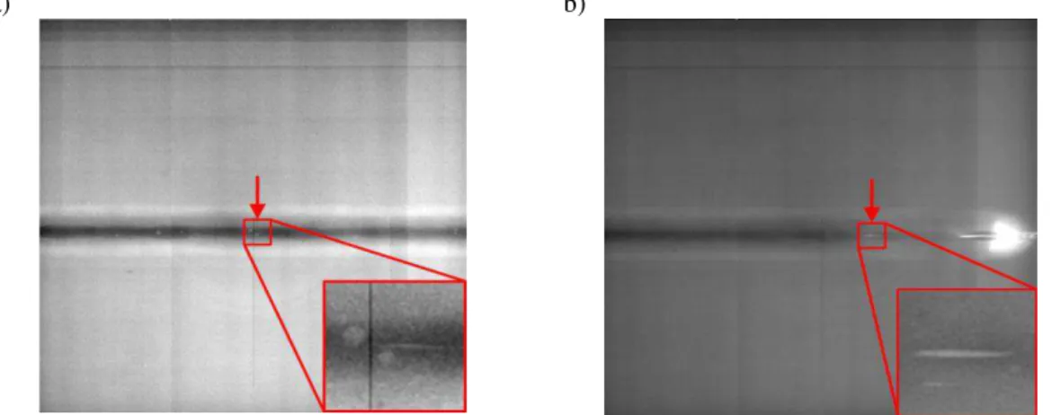
FIGURE 3. X-ray images of about 50 mm x 50 mm of two ROIs: a) position +100 mm and b) position +175 mm. Each inset represents a magnification factor of 5.
DIGITAL X-RAY INSPECTION
To identify any region of interest (ROI) within which internal defects were present, digital radiography inspection of the welded HSLA-65 steel plate was performed. It is noteworthy that to facilitate manipulation of the welded assembly during inspection, the size of the original welded plate was reduced from 400 mm (L) x 480 mm (W) x 9.3 mm (T) to a final dimension of 400 mm (L) x 80 mm (W) x 9.3 mm (T) by sectioning in the base metal region on either side of the weld. Radiographies using an X-ray micro-CT system (Nikon HMXST 225) were obtained. The inspection surface area for each radiography was about 50 mm x 50 mm with a resolution of 25 m. Once concatenated, the X-ray images comprised the entire length of the hybrid laser-arc weld, as revealed in Fig. 2. Two ROIs were observed using this inspection method as demarcated by the arrows in Fig. 2. Magnified images of the ROIs are given in Fig. 3 with the arrows denoting internal crack (linear) defects. The length of the crack defect along the welding direction was about 1.0 mm in the ROI around +100 mm and 1.7 mm in the ROI around +175 mm, with the latter located in the weld runoff. Within the weld, some porosity was also observed in each ROI.
LASER-ULTRASONIC INSPECTION
Laser ultrasonics, which uses lasers for the generation and detection of ultrasound, was also considered for non-contact inspection with the intent of inline implementation [11] immediately following automated fabrication via the HLAW process. The approach used to identify the different types of flaws in the hybrid laser-arc welds is depicted in Fig. 4. For use with SAFT, the generation and detection zones overlapped at the surface of the welded assembly. Ultrasound generation was performed in the slight ablation regime with a short pulse Nd:YAG laser in its 3rd harmonic (6 mJ, 35 ps pulse duration, 355 nm wavelength) to achieve high frequencies and a laser spot size of about 100 m. For detection, a long pulse Nd:YAG laser (40 mJ, 60 s duration, 1064 nm wavelength) and a similar spot size of about 100 m were used. The phase demodulator was a GaAs photorefractive interferometer [12]. Frequencies up to 80 MHz were successfully generated and detected in the weld region. Mechanical scanning along
two axes was performed for data acquisition of all waveforms with a step size of 0.1 mm. An average of 4 signals was used to increase the signal-to-noise ratio (SNR) at each point.
For numerical focusing, a 3D-SAFT algorithm in the Fourier domain for time-efficient reconstruction, which could account for the surface variations induced by the HLAW process, was used [13, 14]. But due to the curved top surface (crown reinforcement) of the weld, the measurements in this initial study were performed from the weld root surface that had greater planarity than the top surface. The data was then processed with SAFT to allow synchronization of the ultrasonic signals scattered back in different directions from each point within the weld region. The SAFT processing was performed using an aperture angle of 40o and a frequency bandwidth from 2 to 80 MHz.
Using these experimental conditions, a surface inspection area of 15 mm x 15 mm was examined in the ROI around +175 mm (in the weld runoff). SAFT reconstruction was performed for depths between 0 and 12 mm from the weld root surface. C-scan images at the different depths are summarized in Fig. 5. Each C-scan was obtained using the maximum-minimum amplitudes in the depth range from the weld root surface, as respectively labeled below each image in Fig. 5. Pores were observed at the intersection of the cursors demarcated in each image. The most interesting depth range is between 4 and 5 mm from the weld root surface where an internal crack defect was also observed. This crack defect appeared to be more or less continuous, as detected from the B-scan (Fig. 6) that was taken along the vertical cursor in the C-scan image at 4 to 5 mm.
Under similar experimental conditions, the ROI around +100 mm was also evaluated from the weld root surface with an inspection area of 15 mm x 15 mm. As before, SAFT reconstruction was performed for depths between 0 and 12 mm from the weld root surface. Similar to that observed for the ROI around +175 mm, the depth range where the defects were detected in the ROI around +100 mm was between 4 and 5 mm from the weld root surface. The resulting C-scan image is given in Fig. 7a where indications of defects (most likely porosity) were clearly observed. The B-scan along the vertical cursor demarcating one of the defects in Fig. 7a, is shown in Fig. 7b. However, the crack defect observed from the X-ray inspection (Fig. 3a) is not visible in Fig. 7, at least when inspecting from the weld root surface, as discussed further in the metallographic examination section.
FIGURE 4. Schematic diagram depicting laser-ultrasonic inspection with SAFT.
FIGURE 5. C-scan images in the different depth ranges from the weld root surface for the ROI around +175 mm. Defect Inspected part
Generation laser
Detection laser & interferometer
Defect Inspected part Generation laser Detection laser & interferometer
4 to 5 mm
5 to 6 mm
6 to 7 mm
3 to 4 mm
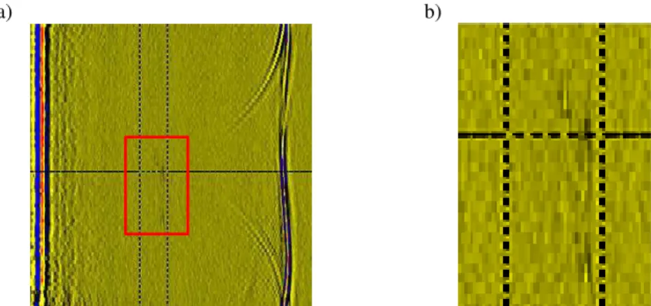
Weld axisa)
b)
FIGURE 6. a) B-scan image parallel to the welding direction of the crack defect demarcated by the vertical cursor in Fig. 5 (4-5 mm depth) and b) magnified image of the region within the box delineated in a).
a) b)
FIGURE 7. a) C-scan image in the 4 to 5 mm depth range from the weld root surface for the ROI around +100 mm and b) B-scan image along the vertical cursor demarcated in a).
FIGURE 8. B-scan image perpendicular to the welding direction with the weld root and crown surfaces located on the top and bottom, respectively.
To this end, Fig. 8 is a B-scan image perpendicular to the welding direction that demonstrates the surface profile of the weld nugget on the top (crown) with the inspection on the bottom (root) surface. The maximum surface height is about 1.2 mm over a width of 7 mm. The surface profile shows an inclination reaching about 30o, which corresponds to specular reflections at 60o from the propagation axis of the incident beam. Such high angles of reflection would necessitate an optical system with a larger numerical aperture in order to reach an acceptable signal level. This was the reason for limiting the measurements to the more planar weld root in this initial study.
a) b)
0.09 mm porosity located at 96 mm Porosity and crack defects located at 175 mm
0.59 mm porosity located at 100 mm Crack defect located at 176 mm
0.40 mm porosity located at 101 mm Crack and LOF defects located at 177 mm
Crack defect located at 102 mm LOF defect (zoom) located at 177 mm
FIGURE 9. Metallographic images of the welding defects observed in the transverse cross-sections of the hybrid-laser arc weld in the a) ROI around +100 mm and b) ROI around +175 mm (within the weld run-off).
METALLOGRAPHIC EXAMINATION
After NDE, the samples for metallographic examination, having a size 15 mm x 15 mm, were extracted from the weldment in the ROI around +100 mm and +175 mm (weld runoff), where the porosity and internal crack defects were detected by the X-ray and laser ultrasonic inspection methods. These metallographic samples were extracted by sectioning, and then mounted, ground and polished. An inverted optical microscope (Olympus GX71) equipped with the Olympus Stream image analysis software was used to examine the transverse cross sections of weld in the ROI around +100 mm and +175 mm. Overall, the defects observed (Fig. 9) appear to correspond well to the results from the X-ray and laser ultrasonic-SAFT inspection. For instance, most of the pores observed in the metallographic
Porosity Crack Porosity
images in the ROI around +175 mm and +100 mm were detected by both NDE techniques. An exception was the 0.09 mm pore observed in the metallographic image taken from the ROI around +96 mm that was not apparent through the X-ray or laser-ultrasonic SAFT inspection, and may be attributed to the resolution limit of the NDE techniques under the experimental conditions utilized. Also, the lack of fusion (LOF) defect, apparent in the metallographic image taken from the ROI around +177 mm, was detected in the X-ray image and laser-ultrasonic SAFT C-scan image. In the case of the cracks observed in the metallographic images taken from the ROI around +177 and +102 mm, the X-ray image showed indications for both linear defects. However the laser-ultrasonic SAFT inspection detected only the crack defect in the ROI around +175 mm. As such, the use of the generated shear wave (S-wave) was also explored, but it did not allow observation of the fine crack in the ROI around +100 mm. It is noteworthy that the S-wave is weak at small angles and the sensitivity is poor due to the inclination of the weld root surface. Hence further work on laser ultrasonic inspection methodology development would be needed to distinguish a thin crack as detected in the ROI around +100 mm through metallography.
CONCLUSIONS
Laser-ultrasonic and digital X-ray inspection results for hybrid laser-arc welded HSLA-65 steel are reported in this paper. These results obtained clearly show the potential of using the laser-ultrasonic technology for the automated inspection of such welds, ultimately inline during manufacturing.
In this initial study, the weld root surface was used for inspection. Preliminary results on a 9.3 mm thick butt-welded HSLA-65 steel plate indicated that laser-ultrasonic SAFT inspection can successfully detect and visualize the presence of porosity and lack of fusion. The case of internal cracks appears more challenging especially when such a linear defect is small or fine. Specifically, one such linear defect was missed using the laser-ultrasonic SAFT inspection, though its presence was confirmed by digital X-ray inspection and metallography. Further work is required to detect such linear defects. In this regard, it is worth mentioning that the inclination of the front surface of the weld and the low surface optical reflectivity are challenging. These difficulties could be overcome using a larger collection aperture than that used in this work. The surface profile of the weld would also have to be measured and taken into account in the SAFT processing algorithm.
ACKNOWLEDGMENTS
The authors are grateful to E. Poirier and X. Pelletier for their technical assistance in conducting the weld trials and metallographic preparation and imaging of the weld cross-sections.
REFERENCES
1. C. Bagger, F.O. Olsen, J. Laser Applications 17, 2-6 (2005).
2. B. Ribic, T.A. Palmer, T. DebRoy, Int. Mater. Reviews 54, 223-244 (2009).
3. V. Caccese, P.A. Blomquist, K.A. Berube, S.R. Webber, N.J. Orozco, Marine Structures 19, 1-22 (2006). 4. X. Cao, P. Wanjara, J. Huang, C. Munro and A. Nolting, Mater. Des. 32, 3399–3413 (2011).
5. A. Nolting, C. Munro, X. Cao, P. Wanjara, CMQ 51, 336-345 (2012).
6. C. Munro, A.E. Nolting, X. Cao, P. Wanjara, Mat. Sci. Forum 706-709, 2992-2997 (2012). 7. X. Cao, P. Wanjara, A. Bernard, D. Pudo, C. Munro, A.E. Nolting, Mat. Sci. Forum (2014).
8. E. Todorov, B. Nagy, S. Levesque, N. Ames, J. Na, Review of Progress in Quantitative Nondestructive Evaluation, AIP Conf.
Proc. 1511, 1065-1072 (2013).
9. C. Mandache, D. Lévesque, L. Dubourg, P. Gougeon, Sci. and Technol. Welding and Joining 17, 295-303 (2012). 10. D. Lévesque, L. Dubourg, A. Blouin, Nondestr. Testing and Eval. 26, 319-333 (2011).
11. J.-P. Monchalin, Review of Progress in Quantitative Nondestructive Evaluation 23A, ed. by D.O. Thompson and D.E. Chimenti, AIP Conf. Proc., 3-31 (2004).
12. A. Blouin, J.-P. Monchalin, Appl. Phys. Lett. 65, 932-934 (1994).
13. D. Lévesque, A. Blouin, C. Néron, J.-P. Monchalin, Ultrasonics 40, 1057-1063 (2002).
14. B. Campagne, D. Lévesque, A. Blouin, B. Gauthier, M. Dufour, J.-P. Monchalin, Review of Progress in Quantitative