Publisher’s version / Version de l'éditeur:
JOM, 66, 12, pp. 2525-2534, 2014-04-04
READ THESE TERMS AND CONDITIONS CAREFULLY BEFORE USING THIS WEBSITE. https://nrc-publications.canada.ca/eng/copyright
Vous avez des questions? Nous pouvons vous aider. Pour communiquer directement avec un auteur, consultez la première page de la revue dans laquelle son article a été publié afin de trouver ses coordonnées. Si vous n’arrivez pas à les repérer, communiquez avec nous à [email protected].
Questions? Contact the NRC Publications Archive team at
[email protected]. If you wish to email the authors directly, please see the first page of the publication for their contact information.
NRC Publications Archive
Archives des publications du CNRC
This publication could be one of several versions: author’s original, accepted manuscript or the publisher’s version. / La version de cette publication peut être l’une des suivantes : la version prépublication de l’auteur, la version acceptée du manuscrit ou la version de l’éditeur.
For the publisher’s version, please access the DOI link below./ Pour consulter la version de l’éditeur, utilisez le lien DOI ci-dessous.
https://doi.org/10.1007/s11837-014-0938-7
Access and use of this website and the material on it are subject to the Terms and Conditions set forth at
Microstructural analysis of linear friction-welded 718 plus superalloy
Vishwakarma, K. R.; Ojo, O. A.; Wanjara, P.; Chaturvedi, M. C.
https://publications-cnrc.canada.ca/fra/droits
L’accès à ce site Web et l’utilisation de son contenu sont assujettis aux conditions présentées dans le site LISEZ CES CONDITIONS ATTENTIVEMENT AVANT D’UTILISER CE SITE WEB.
NRC Publications Record / Notice d'Archives des publications de CNRC:
https://nrc-publications.canada.ca/eng/view/object/?id=f3ab6862-5228-4280-a3bb-b750c6fb63ce https://publications-cnrc.canada.ca/fra/voir/objet/?id=f3ab6862-5228-4280-a3bb-b750c6fb63ceMicrostructural Analysis of Linear Friction-Welded 718 Plus
Superalloy
K.R. VISHWAKARMA,1,3O.A. OJO,1P. WANJARA,2 and M.C. CHATURVEDI1
1.—Department of Mechanical and Manufacturing Engineering, University of Manitoba, Winni-peg, MB R3T 5V6, Canada. 2.—National Research Council Canada, Montreal, PQ H3T 2B2, Canada. 3.—e-mail: [email protected]
The microstructure of Allvac 718 Plus (718 Plus; ATI, Pittsburgh, PA, USA) superalloy was examined after linear friction welding (LFW) and after stan-dard postweld heat treatment (PWHT). The liquid phase reaction of second-phase precipitates, which are known to constitutionally liquate during con-ventional fusion welding, was observed in the thermomechanically affected zone (TMAZ) of the welded material. These phases included MC-type carbides, Ti-rich carbonitrides, and d phase precipitates. This observation is contrary to the general assumption that LFW is a completely solid-state joining process. However, unlike conventional fusion welding processes that cause heat-af-fected zone liquation cracking in 718 Plus and many other superalloys, the LFW process did not cause cracking in 718 Plus superalloy despite the liquation of precipitates. This absence of cracking during joining is attributed to the applied compressive stress during the forging stage of the LFW process. Also, no cracking was observed after PWHT, although PWHT resulted in a microstructure that had a nonhomogeneous distribution of precipitates in the weld and the TMAZ.
INTRODUCTION
Allvac 718 Plus (718 Plus; ATI, Pittsburgh, PA) was developed from conventional Inconel 718 to have a higher working temperature and superior creep properties while maintaining good formabil-ity. It can be used at temperatures up to 700°C, which is about 50°C higher than the upper tem-perature limit for Inconel 718, and it has creep strength similar to that reported by Waspaloy (United Technologies Corp., Hartford, CT).1 718 Plus is precipitation strengthened by the ordered c¢ phase, although it has a lower volume fraction compared to other c¢-strengthened alloys. Previous investigations on fusion welding of 718 Plus using electron beam (EB)2as well as laser beam3showed that 718 Plus undergoes heat-affected zone (HAZ) microfissuring during welding and postweld heat treatment (PWHT) due to liquation effects.
Linear friction welding (LFW) offers an attractive alternative to the conventional welding processes used for manufacturing and repair of aerospace components. It involves joining of components using
frictional heat produced by their relative motion and the applied forging pressure. The LFW process can be broadly classified into four distinctive steps, as outlined by Varis et al.4: (I) the initial stage where sufficient heat is generated due to solid fric-tion, (II) the transition stage where the contact moves beyond the interface expelling the asperities, (III) the equilibrium stage that involves further generation of heat and joining at the interface, and (IV) the deceleration stage where the movement of the components is stopped and followed by the application of a forging pressure. The resulting microstructure consists of the weld interface, the thermomechanically affected zone (TMAZ), and the unaffected base alloy. Depending on the position in the weldment, different regions of the TMAZ and the base alloy are subjected to different ranges of temperatures and plastic deformation that influ-ence microstructural development. LFW has been successfully used to join steel5 and titanium al-loys6,7in applications including manufacturing and repair of turbine components. For Ni-base superal-loys, LFW has been used to weld polycrystalline,8
JOM, Vol. 66, No. 12, 2014
DOI: 10.1007/s11837-014-0938-7
Ó2014 Her Majesty the Queen in Right of Canada as represented by: NRC Canada
cast,9 dissimilar,10 and single-crystal materials.11 This joining process is generally considered to be a completely solid-state joining process,12 and like other friction-welding processes, it could eliminate problems associated with melting and resolidifica-tion of convenresolidifica-tional fusion welding techniques. However, some recent studies suggest that liquation does occur in TMAZ during the LFW process in single-crystal CMSX-48613 and IN 738,14 although no such study exists for 718 Plus alloys. As liquation could result in microfissuring, LFW was used to weld 718 Plus to examine the feasibility of the technique and its effect on the microstructure of the alloy. The results of the study are presented and discussed in this article.
EXPERIMENTAL PROCEDURES The as-received 718 Plus alloy was in the form of 15.9 mm 9 304.8 mm 9 127 mm hot-rolled plates with a chemical composition of (wt.%) 17.92 Cr, 9.00 Co, 52.18 Ni, 9.33 Fe, 1.50 Al, 0.74 Ti, 5.51 Nb, 2.68 Mo, 1.04 W, 0.003 B (30 ppm), and 0.006 P (60 ppm). Test coupons measuring 12.8 mm 9 11.1 mm 9 17.7 mm were machined from the as-received plates and were solution treated at 950°C for 1 h followed by water quenching. Prior to welding, the contact surfaces of the coupons were ground and cleaned with alcohol. LFW was performed at ambient tem-perature under prevailing atmospheric conditions using an MTS LFW Process Development System (PDS; MTS, Eden Prairie, MN, USA) located at the National Research Council of Canada. The technical specifications of the equipment are described else-where.15Previous work on LFW of Inconel 718 using processing conditions of 80 Hz for the frequency (f), 2 mm for the amplitude (a), 70 MPa for the forging pressure (P), and 2 mm for the axial shortening (s) indicated that only the center section of the welded coupons was bonded.16 To extend bonding to the periphery regions, in the current work on LFW of 718 Plus, the frequency was increased to 100 Hz and the pressure to 90 MPa. Welded specimens were sub-jected to the standard PWHT, which consisted of holding at 950°C for 1 h followed by air cooling, aging at 718°C for 2 h, and then at 650°C for 8 h followed by air cooling. Cross sections of the as-welded and postweld heat-treated samples in the long transverse direction were used for microstructural analysis. Metallographic specimens were etched by swabbing using modified Kalling’s reagent and electrolytically in 10% oxalic acid. Samples were also electrolytically etched in a mixture of 12 mL H3PO4+ 40 mL
HNO3+ 48 mL H2SO4at 6 V for 5–6 s to reveal the
c¢ phase in the microstructure. The weld zone, base alloy, and TMAZ microstructures were examined and analyzed using an optical microscope, JEOL 5900 scanning electron microscope (SEM; JEOL Ltd., Tokyo, Japan) equipped with an ultrathin window energy dispersive spectrometer (EDS; Ox-ford Instruments, OxOx-fordshire, UK), and JEOL 2000
FX transmission electron microscope (TEM). Thin foils for TEM were produced by twin-jet polishing with 10% perchloric acid in 90% methyl alcohol at a temperature of 20°C to 30°C with a current of 1.5 A current and a voltage of 2 V. The grain size distribution across the weld joint was also examined by electron backscatter diffraction (EBSD)-based orientation imaging microscopy (OIM) equipped on Phillips XL 80 environmental scanning electron microscope (ESEM; Philips, Amsterdam, The Neth-erlands).
RESULTS AND DISCUSSION
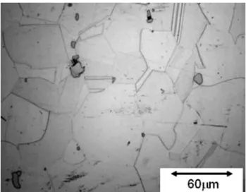
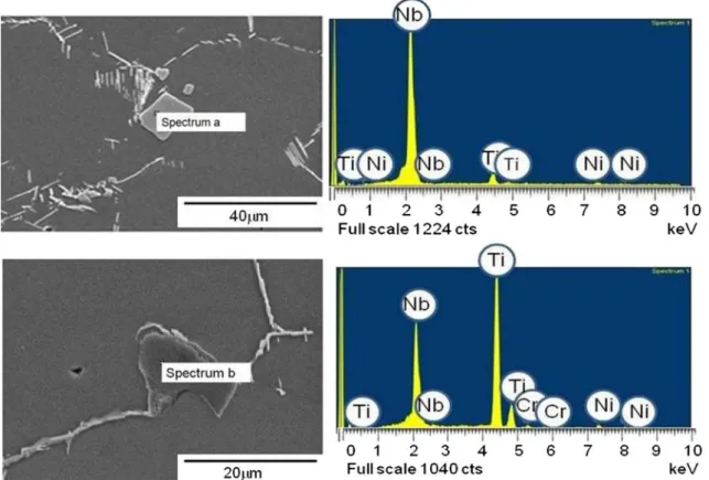
As-received and Solutionized Microstructure The as-received microstructure of 718 Plus con-sisted of a face-centered cubic (fcc) c matrix with randomly dispersed second-phase particles as shown in the optical micrograph in Fig.1. SEM/ EDS analysis was used to identify the second-phase particles by their morphology and chemical compo-sition. Blocky particles, shown in Fig.2a, were predominantly rich in Nb with a small percentage of Ti and were identified to be MC-type carbides, whereas the irregular-shaped particles shown in Fig.2b were mainly Ti–rich carbonitrides. The composition of these particles, as determined by the SEM/EDS semiquantitative analysis, is presented in TableI alongside the matrix composition. The other commonly found precipitate in 718 type alloys is the orthorhombic d phase, which was not ob-served in the microstructure of 718 Plus alloy. The absence of d phase in the as-received microstructure may be due to the use of a homogenization heat-treatment temperature that was above the solvus temperature of the d phase followed by rapid cool-ing. Thin foils examined in TEM also revealed the presence of fine particles, as shown in Fig.3. The inset in Fig.3b shows that the selected-area dif-fraction pattern (SADP), obtained in [001] thin-foil Fig. 1. Light optical image of the microstructure of as-received 718 Plus showing randomly distributed second-phase particles.
orientation, contained the (100)-type superlattice reflections in it, suggesting the precipitates to be c¢ phase. The dark-field image taken from one such reflection confirms the identity of these particles to be c¢ phase. TableII lists the average grain size of the as-received material and presents the approxi-mate sizes of the phases as observed in the micro-structure.
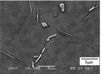
Figure4 shows the microstructure of 718 Plus after solutionizing at 950°C for 1 h followed by wa-ter quenching. The amount and distribution of the MC-type carbides and Ti-rich carbonitrides was not considerably altered by the heat treatment (Fig.5a), but the heat treatment resulted in the precipitation
of d phase particles. The orthorhombic d phase was mostly present at the grain boundaries, with either small or large needle-like morphology or in the platelet form. The major strengthening precipitates of the alloy c¢ were uniformly distributed throughout the microstructure, as shown in Fig.5b.
As-welded Microstructure
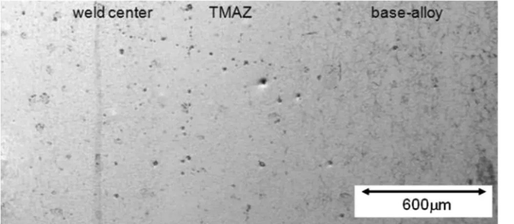
The LFW process produced integral crack-free welds in the 718 Plus alloy. Figure6 shows a low-magnification optical micrograph of the micro-structure of the as-welded 718 Plus alloy. The microstructure can be divided into three distinct zones, as identified in the micrograph, specifically, the base alloy matrix, TMAZ, and the weld center.
In comparison to the previous work on Inconel 71816 the current processing conditions of higher frequency and pressure produced an integral weld along the entire cross section of the joint. In the current work, except for a few carbides, the weld region did not comprise of any second-phase parti-cles, such as d phase and c¢ precipitates. The most striking feature of the weld center was the change in the grain size. A comparison of the grain sizes in the base alloy and that in the weld center is shown in an optical micrograph in Fig.7. This is further corrob-orated by EBSD-based orientation mapping (Fig. 8) showing individual grains in random colors for the weld center and the base alloy. The average grain size in the weld zone was observed to be significantly Fig. 2. (a) NbC particle with the EDS spectrum and (b) Ti(C,N) particle with the EDS spectrum.
Table I. Average chemical composition of the second-phase particles and matrix as determined by SEM EDS analysis in 718 Plus alloy
wt.% Matrix NbC Ti(C,N) Laves phase d phase
Al 1 1 2 Ti 1 8 63 5 1 Cr 18 1 5 16 17 Fe 9 2 8 9 Co 10 9 10 Ni 53 2 10 50 55 Nb 4 89 20 11 6 Mo 3 3 W 1 2 1
smaller than it was in the base alloy. That is, across a region of about 30 lm from the weld line, the grain size was about 3 lm as compared to the 50-lm grain size of base alloy (TableII). Beyond 30 lm from the weld line, the grain size increased progressively, inevitably due to recrystallization kinetics (i.e., decreasing Zener–Holloman parameter), which stems from the gradients in temperature and strain as reported recently for linear friction-welded Waspaloy.17At about 100 lm from the weld line, the average grain size in the TMAZ was similar to that of the base alloy. The fine recrystallized grains in the weld center were also observed by Ola et al.14in the linear friction-welded Inconel 738. They suggested that the presence of such fine grains could not be solely explained by classic solid-state recrystalliza-tion theory and may be associated with the liquarecrystalliza-tion and resolidification of phases within the alloy. The nonequilibrium liquation phenomenon and the strain-induced rapid solidification were proposed to explain the formation of fine grains in the weld cen-ter.14,18The fine grain size is a characteristic feature of the linear friction welds, which has been also ob-served in Inconel 71815and Waspaloy.19
Microstructural characterization of the TMAZ in the linear friction welds showed features that were consistent with grain boundary liquation and con-stitutional liquation of second-phase particles, as was observed during fusion welding of 718 Plus al-loy.2 Liquation is generally not expected during a solid-state joining process, like LFW, because the temperature reached during the process is below the solidus temperature of the alloy. However, subsoli-dus liquation can occur by nonequilibrium processes like constitutional liquation of second-phase parti-cles and by lowering of the melting point of the alloy due to segregation of melting point depressants.
Constitutional liquation, as proposed by Pepe and Savage in 19677,20 states that localized melting is
possible below the equilibrium solidus temperature of the alloy when a rapid heating rate is involved. During LFW, the heating rate has been suggested to be as high as 368°C/s ± 140°C/s,19 which could in-duce nonequilibrium liquation of second-phase par-ticles. Constitutional liquation of second-phase particles during conventional fusion welding pro-cesses has been observed in 718 Plus alloy; however, its occurrence in linear friction welds has not been reported previously.
In the current work, many grain boundaries were observed to have liquated, with the presence of characteristic resolidified phases on them, as shown in Fig.9. The liquated grain boundaries in the TMAZ were distinctly of two types, as marked ‘‘A’’ in Fig.10 and type B as shown in a higher magnification image of the TMAZ region (inset of Fig.10). Type A grain boundaries were devoid of any precipitates, which is in contrast to the precipitate bearing type B grain boundaries. The grain boundaries of type A had a conspicuously different wavy pattern of resolidifica-tion. The zigzag nature of these grain boundaries is typical of liquid film migration (LFM). LFM has been observed in the HAZ of several Ni-base superalloys welded by conventional fusion welding techniques and linear friction-welded IN 738 superalloy.3,21,22 Under certain conditions, liquated regions of grain boundaries in the HAZ in these alloys can solidify via LFM instead of the normal solidification mode that result in the formation of resolidified products. LFM, on the other hand, is a faster solidification mode and can result in resolidified products being not present on them depending on the thickness of the liquated grain boundary and the concentration of alloying elements of the liquid.21
Fig. 3. As-received 718 Plus alloy: (a) bright-field image of the matrix and (b) selected-area diffraction pattern in the direction parallel to [001] zone axis.
Grai n boundaries such as ty pe B, show n in inset of Fig. 10 wer e caref ully analyzed using SEM EDS anal ysis to stud y the nature of the phases present, and Table I show s the chemic al compo sition of o ne Fig. 4. Light optical image of the as-welded base alloy microstruc -ture.
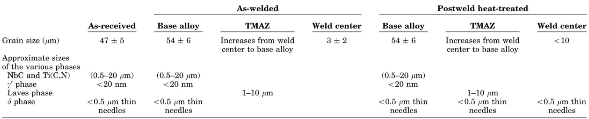
Table II. Average grain size in as-received, as-welded, and postweld heat-treated 718 Plus and approximate sizes of the various phases as observed in the microstructure
As-received
As-welded Postweld heat-treated
Base alloy TMAZ Weld center Base alloy TMAZ Weld center
Grain size (lm) 47 ± 5 54 ± 6 Increases from weld
center to base alloy
3 ± 2 54 ± 6 Increases from weld
center to base alloy
<10 Approximate sizes
of the various phases
NbC and Ti(C,N) (0.5–20 lm) (0.5–20 lm) (0.5–20 lm) c¢ phase <20 nm <20 nm <20 nm Laves phase 1–10 lm 1–10 lm d phase <0.5 lm thin needles <0.5 lm thin needles <0.5 lm thin needles <0.5 lm thin needles <0.5 lm thin needles Fig. 5. (a) Seconda ry electron image of the as-welde d base alloy showing gamma prime particles and delta phase at the grain boundaries (etched by gamma prime etchant) and (b) shows MC carbides and carbonitride particles (etched by Kalling’s etchant). Microstructural Analysis of Linear Friction-Welded 718 Plus Superalloy 2529
such phase. As can be seen from the data presented, these particles have a chemical composition that is distinctively different from those of carbides and carbonitride particles. However, the chemistry of
these particles is similar to that of d phase and Laves phase, both of which have a similar chemical composition but very different morphologies. It was observed that the morphology of these particles is Fig. 6. Microstructure of the linear friction-welded 718 Plus showing the weld center, TMAZ, and the base alloy.
Fig. 7. (a) Recrystallized grains at the weld center and (b) grains in the base alloy; both figures have the same magnification.
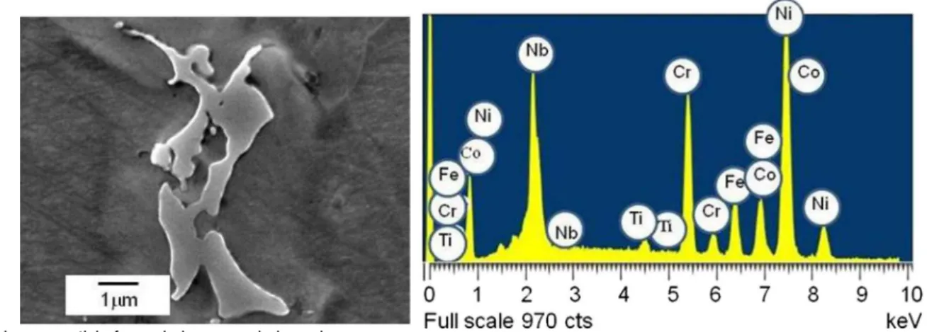
different from that of the d phase particles but is similar to that of Laves phase particles.2Therefore, based on the chemical analysis and morphology, these products are suggested to be Laves phase. Figure11 shows one such particle and the
corre-sponding EDS analysis spectrum. Laves phase particles usually form in Inconel 718 type alloys during solidification. In a previous metallurgical analysis of 718 Plus alloys, Laves phase particles were not observed in wrought alloys2; however, they can form by a solidification reaction during con-ventional arc welding. Hence, based on this discus-sion, it is suggested that Laves phase particles in linear friction-welded 718 Plus could have been produced by liquation and solidification in the form of Laves + c eutectic. The solidification process in Inconel 718 and 718 Plus alloys is generally believed to terminate by the formation c + Laves eu-tectic.23,24 The c phase in the Laves + c eutectic appears to have blended with the primary c matrix, although a halo indicative of the resolidified c can be observed around the Laves phase separating it from the prior c matrix, as seen in the Fig. 11. The for-mation of Laves phase particles has been found to be detrimental to the mechanical properties of the al-loy due to their brittle nature.25However, it is to be noted that Laves phase particles form in the weld zone in conventionally welded wrought Inconel 718, whereas Laves phase particles were not observed in the weld zone (weld center) in the linear friction-welded 718 Plus alloy. This could be attributed to strain-induced rapid solidification that prevents the formation of eutectic products within the weld zone.18
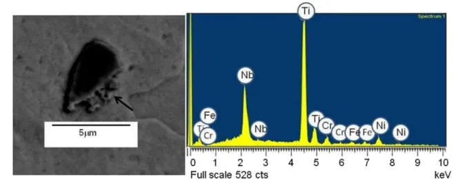
The morphology of the carbides and carbonitride particles present in the TMAZ (Fig.12) appeared to be different from those present in the base alloy (inset in Fig. 5). The particles in the base alloy exhibited a well-defined boundary, whereas those in the TMAZ had serrated boundaries, which is typical of liquated particles. The backscattered SEM ima-ges of Ti-rich carbonitride particles and Nb-rich MC type carbides, with their EDS spectra, are shown in Figs.12 and 13, respectively. Constitutional liqua-tion of carbides and carbonitrides is a well-estab-lished phenomenon in conventional fusion welding of 718 type superalloys. Similar features associated with grain boundary liquation cracking in the HAZ Fig. 9. Transgranular and grain boundary regions in TMAZ of
as-welded 718 Plus linear friction weld.
Fig. 10. LFM and precipitates on the grain boundaries in the as-welded TMAZ microstructure.
Fig. 11. Laves particle formed along a grain boundary.
of EB-welded 718 Plus were observed in a previous investigation by the current authors.2,26 The char-acteristics of the particles that appear to have formed by liquation and resolidification reactions in linear friction-welded 718 Plus are comparable with those observed in the EB welds of the alloy,26 al-though unlike the EB welds, no microfissuring was observed during LFW. The occurrence of grain boundary liquation is not a sufficient condition for cracking to occur. Generation of sufficient tensile stresses at a time when the grain boundary regions are weakened by the presence of liquid phase is necessary to cause cracking by decohesion along one of the solid–liquid interfaces. Preclusion of inter-granular cracking in the current work could be re-lated to the imposition of compressive stress during the forging stage of the LFW process, which may have countered the driving force for cracking, that is, the tensile stress.
The d phase particles, which are characteristically present at the base alloy grain boundaries prior to welding, were completely dissolved in the TMAZ. The rapid dissolution of d phase particles is likely to be due to the intergranular liquation reaction involving the d phase. The contribution of d phase to
intergranular liquation has been reported in earlier studies in both Inconel 718 and 718 Plus alloy.27,28 It was proposed that d phase particles dissociate above their solvus (about 1010°C in Inconel 718)29 and enrich the grain boundary with Nb, a melting point depressant, which lowers the melting point of the grain boundary region, resulting in intergran-ular liquation. This is called d phase assisted liquation.28 However, Zhang and Ojo30 observed that d phase can actually constitutionally liquate in the HAZ during welding.
Postweld Heat-Treated Microstructures PWHT is generally aimed at homogenizing the weld microstructure and relieving the residual welding stresses. In the current work, the standard PWHT for 718 Plus alloy was used. The base alloy microstructure of postweld heat-treated alloy 718 Plus consisted of coarse NbC and d phase particles at the grain boundaries with uniform distribution of c¢ precipitates within the grains, as shown in Fig.14. A transition from the base alloy to the TMAZ is apparent in the postweld heat-treated samples by a change in the amount and distribution
Fig. 12. Ti(C,N) particle in the TMAZ and its EDS spectrum.
of second-phase particles. A marked difference in the amount of c¢ particles was observed between the TMAZ and base alloy. It was observed that the ex-tent of c¢ precipitation in TMAZ was considerably less than that observed in the base alloy, and the distribution seems to be nonuniform in nature (Fig.15). Similarly, the extent of d phase precipi-tation was less in the TMAZ compared to that in the base alloy, and the particles were more pronounced in certain regions within the grains and around certain phases. Figure16 shows a grain boundary in the TMAZ region of the postweld heat-treated weld that exhibited clusters of precipitates. One significant observation is that the intergranular and transgranular regions that appear to have liquated during welding, consistently showed a higher extent of d phase precipitation.
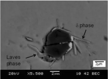
PWHT could not eliminate the Laves particles that formed during the welding process, rather d phase precipitation was observed around them, as shown by one such case in Fig.17. Similarly, in-creased precipitation of d phase was observed around carbides and carbonitride particles (Figs.17 and 18). A comparison of Figs.18 and 14 shows that, unlike in the TMAZ region, carbide and car-bonitrides particles in the base alloy in the postweld heat-treated condition do not have any Laves par-ticles associated with them. Because Laves phase can only form during solidification from the liquid state, this observation further supports the sug-gestion that liquation likely occurred in the TMAZ during LFW.
Similar to the as-welded condition, no microfis-suring was observed in the postweld heat-treated linear friction-welded 718 Plus alloy. The current work indicates that with the process parameters used, 718 Plus can be welded by the LFW process without cracking. However, phase reactions that Fig. 14. Base alloy microstructure after PWHT.
Fig. 15. Transition from base alloy to TMAZ microstructure in post-weld heat-treated alloy.
Fig. 16. Nonuniform distribution of c¢ phase in the TMAZ of postweld heat-treated 718 Plus weld.
Fig. 17. Laves particle and d phase particle in the TMAZ after PWHT.
occurred during welding appear to result in the formation of Laves phase particles, which are known to be detrimental to the mechanical proper-ties. Also, non-uniform distribution of precipitates after the PWHT, including that of the c¢ phase, could adversely affect the high-temperature prop-erties of the alloy. Hence, the occurrence of liquation and its likely influence on postweld heat-treated microstructure are important factors that merit more in-depth consideration for qualifying the application of LFW to 718-type alloys.
SUMMARY AND CONCLUSION
1. LFW of Inconel 718 Plus with a frequency of 100 Hz, pressure of 90 MPa, amplitude of 2 mm, and axial shortening of 2 mm produced a sound weld without microfissuring.
2. The weld region consisted of fine recrystallized grains, and although intergranular liquation appears to have occurred in the TMAZ, weld cracking was not observed.
3. Grain boundary liquation resulted in the forma-tion of Laves phase and inhomogeneous precipi-tation of the principle-strengthening precipitatec¢ during PWHT.
4. The absence of microfissuring in the linear friction-welded alloy may be attributed to the compressive stresses applied to the joint region during the forging phase of LFW, which may be responsible for the absence of resolidification eutectic products in the weld center.
ACKNOWLEDGEMENTS
The authors would like to thank Natural Sciences and Engineering Research Council of Canada for
the financial support. The technical assistance of M. Guerin and E. Dalgaard for LFW of IN 718 Plus is also greatly appreciated.
REFERENCES
1. W.D. Cao and R. Kennedy, Superalloys, ed. K.A. Green, T.M. Pollock, H. Harada, T.E. Howson, R.C. Reed, J.J. Schirra, and S. Walston (Warrendale, PA: TMS, 2004), pp. 91–99.
2. K.R. Vishwakarma, N.L. Richards, and M.C. Chaturvedi, Mater. Sci. Eng. A Struct. 480, 517 (2008).
3. O. Idowu, O.A. Ojo, and M.C. Chaturvedi, Mater. Sci. Eng. A Struct. 454–455, 389 (2006).
4. A. Varis and M. Frost, Mater. Sci. Eng. A Struct. 292, 8 (2000).
5. I. Bhamji, M. Preuss, P.L. Threadgill, R.J. Moat, A.C. Addison, and M.J. Peel, Mater. Sci. Eng. A Struct. 528, 680 (2010).
6. E. Dalgaard, P. Wanjara, J. Gholipour, and J.J. Jonas, Can. Metall. Q. 51, 269 (2012).
7. E. Dalgaard, P. Wanjara, J. Gholipour, X. Cao, and J.J. Jonas, Acta Mater. 60, 770 (2012).
8. A. Chamanfar, M. Jahazi, J. Gholipour, P. Wanjara, and S. Yue, Mater. Sci. Eng. A Struct. 555, 117 (2012).
9. O.T. Ola, O.A. Ojo, P. Wanjara, and M.C. Chaturvedi, Adv. Mater. Res. 278, 446 (2011).
10. S.V. Lalam, G.M. Reddy, T. Mohandas, M. Kamaraj, and B.S. Murty, Mater. Sci. Tech. Ser. 25, 851 (2009).
11. P. Wanjara, E. Dalgaard, J. Gholipour, and J. Larose, Ma-ter. Sci. Forum 706–709, 3022 (2012).
12. A. Chamanfar, M. Jahazi, J. Gholipour, P. Wanjara, and S. Yue, Mater. Des. 36, 113 (2012).
13. O.T. Ola, O.A. Ojo, P. Wanjara, and M.C. Chaturvedi, Me-tall. Mater. Trans. A 43A, 921 (2012).
14. O.T. Ola, O.A. Ojo, P. Wanjara, and M.C. Chaturvedi, Me-tall. Mater. Trans. A 42A, 3761 (2011).
15. P. Wanjara and M. Jahazi, Metall. Mater. Trans. A 36A, 2149 (2005).
16. C. Mary and M. Jahazi, Adv. Mater. Res. 15–17, 357 (2007).
17. A. Chamanfar, M. Jahazi, J. Gholipour, P. Wanjara, and S. Yue, Metall. Mater. Trans. A 44, 4230 (2013).
18. O.T. Ola, O.A. Ojo, P. Wanjara, and M.C. Chaturvedi, Phi-los. Mag. Lett. 91, 140 (2011).
19. A. Chamanfar, M. Jahazi, J. Gholipour, P. Wanjara, and S. Yue, Metall. Mater. Trans. A 42, 729 (2011).
20. J.J. Pepe and W.F. Savage, Weld J. 9, 411-s (1967). 21. R. Nakkalil, N.L. Richards, and M.C. Chaturvedi, Acta
Metall. Mater. 41, 3381 (1993).
22. O.A. Ojo, N.L. Richards, and M.C. Chaturvedi, Scr. Mater. 51, 141 (2004).
23. B. Radhakrishnan and R.G. Thompson, Metall. Trans. A 20A, 2866 (1989).
24. B. Radhakrishnan and R.G. Thompson, Metall. Trans. A 23A, 1783 (1992).
25. J.J. Schirra, R.H. Caless, and R.W. Hatala, Superalloys 718, 625, 706 and Various Derivatives, ed. E.A. Loria (Warren-dale, PA: TMS, 1991), pp. 375–388.
26. K.R. Vishwakarma, N.L. Richards, and M.C. Chaturvedi, Superalloys 718, 625, 706 and Various Derivatives, ed. E.A. Loria (Warrendale, PA: TMS, 2006), pp. 637–647.
27. Q. Li (Ph.D. thesis, University of Manitoba, 2006). 28. M. Qian and J.C. Lippold, Acta Mater. 51, 3351 (2003). 29. S. Azadian, L. Wei, and R. Warren, Mater. Charact. 57, 7
(2004).
30. H.R. Zhang and O.A. Ojo, Philos. Mag. Lett. 89, 787 (2009).
Fig. 18. Ti-carbonitride particles with d phase and Laves phase in the postweld heat-treated condition.
![Fig. 3. As-received 718 Plus alloy: (a) bright-field image of the matrix and (b) selected-area diffraction pattern in the direction parallel to [001]](https://thumb-eu.123doks.com/thumbv2/123doknet/14101959.465722/5.890.181.692.99.400/received-bright-matrix-selected-diffraction-pattern-direction-parallel.webp)