Degree Programme
Systems Engineering
Major Infotronics
Diploma 2015
Nicolas Marty
C
C
o
o
l
l
o
o
u
u
r
r
s
s
a
a
n
n
d
d
a
a
n
n
o
o
m
m
a
a
l
l
i
i
e
e
s
s
o
o
f
f
s
s
k
k
i
i
n
n
Professor M a r t i a l G e is e r Expert F ir s t n a m e N a m e Submission date of the report 1 0 . 0 7 . 2 0 1 5This document is the original report written by the student. It wasn’t corrected and may contain inaccuracies and errors.
Ziel des Projekts
Das Ziel ist die Entwicklung einer portablen Kamera mit multispektraler Beleuchtung zur Aufnahme und Analyse von Anomalien der Haut. Anwendungsbereiche sind: a) Analyse und Verfolgung von Muttermalen und Wunden, b) Untersuchung von Einfluss von Cremen
Methoden | Experimente | Resultate
Ein Raspberry Pi dient als Plattform um die Kamera sowie die Beleuchtung, bestehend aus 8 Wellenlängen, zu steuern und die multispektralen Bilder auszuwerten. Die Bilder werden in Kontext mit Patientendaten mittels WLAN auf einen Server hochgeladen. Das kompakte Gerät wird über einen Touchscreen bedient und der Akku kann mithilfe einer Dockingstation wieder aufgeladen werden.
Ein mögliches Szenario wurde mit einem Arzt besprochen und anschliessend in der Software implementiert. In Zusammenarbeit mit einem Studenten der Fachrichtung Wirtschaftsinformatik entstand ein Interface zum Hochladen der Daten zu einer Webapplikation.
Der Raspberry Pi führt selbständig eine Analyse der 8 Rohbilder durch. Die Analyse umfasst die Messung des Melaningehalts und die Rekonstruktion eines RGB-Bildes.
Das System wurde an 5 Probanden getestet. Die Rohbilder und Analysen konnten erfolgreich auf den Server übertragen werden.
Farben und Anomalien der Haut
Diplomand
Nicolas Marty
Diplomarbeit
| 2 0 1 5 |
Studiengang Systemtechnik Anwendungsbereich Infotronics Verantwortliche/r Dozent/in Dr. Martial Geiser martial.geiser@hevs.ch Partner Dr Elisabeth Giannada Dermatologue, Sion OmniMedica SA Schlieren1. LEDs / 2. Optik / 3. Kamera / 4. Beleuchtungssteuerung / 5. Steuerung der Stromversorgung / 6. Akku / 7. Raspberry Pi / 8. WLAN Dongle / 9. Touchscreen
Beispiel einer Aufnahme eines Muttermals. Diese hilft dem Arzt die Anomalie zu beurteilen.
1 2 3 4 5 6 7 8 9
Objective
We developed a handheld camera with multispectral illumination to take pictures and to analyse anomalies of skin. The fields of use are: a) analysing and tracking skin lesions such as naevi or wounds, b) studying influence of creams.
Methods | Experiment s | Results
A Raspberry Pi controls the whole device including camera, illumination and analyse and send data. The illumination consists of 8 different wavelengths. The images are uploaded to a server using WLAN and are always in context with the data of a patient. The handheld device is controlled via a touchscreen and the battery can be recharged using a dedicated docking station.
A possible scenario was discussed with a medical doctor and was subsequently implemented into the software. In cooperation with a student from the institute of information systems, an interface to upload the data to a web application was developed.
The Raspberry Pi performs the analysis of the 8 raw images on its own. The analysis includes the measurement of the melanin concentration and the reconstruction of a RGB image.
The system was tested on 5 subjects. The raw images and the analysis could be transmitted successfully to the server.
Colours and anomalies of skin
Graduate
Nicolas Marty
Bachelor’s Thesis
| 2 0 1 5 |
Degree programme Systems engineering Field of application Infotronics Supervising professor Dr. Martial Geiser martial.geiser@hevs.ch Partner Dr Elisabeth Giannada dermatologist, Sion OmniMedica SA Schlieren1. LEDs / 2. lens / 3. camera / 4. illumination unit / 5. power supply control / 6. battery / 7. Raspberry Pi / 8. WLAN / 9. touch screen
Example of a mole image. This image can help the dermatologist to analyse the anomaly.
1 2 3 4 5 6 7 8 9
Objectif du projet
Afin de suivre et d’analyser l’évolution, lors de traitement ou pas, de lésions de la peau (grains de beauté, plaies, tâches de sénescence, coup de soleil …), nous avons développé une caméra portable munie d’une illumination multispectrale capable d’envoyer les images sur un serveur dédié et d’analyser ces images.
Méthodes | Expériences | Résultats
Un Raspberry Pi pilote la camera et l’illumination multi spectrale composée de 8 différentes longueurs d’onde. Toute la procédure de prise d’images et d’envoi sur un serveur dédié via le WiFi est commandée au travers d’un écran. La batterie est rechargée lorsque l’instrument est posé sur sa station d'accueil.
Un scénario possible, proposé par un dermatologue, est implémenté dans le logiciel. En coopération avec un étudiant de la Haute École d’économie a développé une interface pour télécharger et relire les données vers une application web.
À partir des 8 images brutes le Raspberry Pi effectue une analyse la concentration de mélanine dans la peau et reconstitue image RGB.
Le système a été testé sur 5 sujets. La procédure de prises de vues, d’analyse et d’envoi sur le serveur ont été effectuées avec succès.
Couleurs et anomalies de la peau
Diplômant
Nicolas Marty
Travail de diplôme
| é d i t i o n 2 0 1 5 |
Filière Systèmes industriels Domaine d’application Infotronics Professeur responsable Martial Geiser martial.geiser@hevs.ch Partenaires Dr Elisabeth Giannada Dermatologue, Sion OmniMedica SA Schlieren1. LEDs / 2. Optique / 3. Camera / 4. Contrôle d’éclairage / 5. Contrôle d’alimentation / 6. Batterie / 7. Raspberry Pi / 8. WLAN / 9. Écran tactile
Exemple d’une image d’une tache de vin. Cette image va aider le médecin à analyser l’anomalie.
1 2 3 4 5 6 7 8 9
Nicolas Marty 10. Juli 2015 page 1 of 30
1 Content
2 Preface ... 2 3 Introduction ... 2 4 System Specifications ... 3 4.1 Overview ... 3 4.2 Short Description ... 4 4.2.1 Controller ... 4 4.2.2 Energy Management ... 54.2.3 Camera & Illumination ... 5
4.2.4 Casing ... 5
4.3 Detailled Description ... 6
4.3.1 Controller ... 6
4.3.2 Energy Management ... 16
4.3.3 Camera & Illumination ... 23
4.3.4 Casing ... 25 5 Results ... 27 6 Future Improvements ... 28 7 Conclusion ... 28 8 Sources ... 29 9 Appendix ... 29 10 Signature ... 30
Nicolas Marty 10. Juli 2015 page 2 of 30
2 Preface
I take this opportunity to express gratitude to everyone who helped me with patience and compe-tence during this project. A special thanks to my supervisor Martial Geiser who particularly supported me. A thanks to Frederic Truffer, he gladly answered questions and gave me convenient tips. I also want to thank Olivier Walpen and Serge Amoos who helped me with electronics and casing. Another thank you goes to Michael Clausen who gave useful hints for programming. Finally an acknowledge-ment to dermatologist Dr. Gianadda Elisabeth, who supported us with valuable ideas and standards.
3 Introduction
In recent years there were developed three generations of devices that take images with multispec-tral illumination. These images offer interesting information about anomalies of the skin and the technology shows great potential. The field of use goes from analysing and tracking moles and le-sions, over to studying influence of creams until forensic.
The objective of this project is to develop a handheld device which takes advantage of the existing multispectral imaging technology. It allows the analysis of skin anomalies and transfers the data wire-lessly to a server.
A Raspberry Pi serves as platform to control the camera and the illumination of 8 different wave-lengths. The images are uploaded to a server using WLAN and are in context with the data of a pa-tient. The handheld device is controlled via a touchscreen and the battery can be recharged using a dedicated docking station.
Nicolas Marty 10. Juli 2015 page 3 of 30
4 System Specifications
4.1 Overview
«view detailed results» Docking Station Database PC Doctor Patient Casing ControllerRaspberry Pi Touch-Display
WiFi Button Camera Lens Lightning IDS uEye Camera Energy Management Battery Electronics power Micro USB «use» «take photos»
SPI & I2C USB USB power power UART / interruptions WLAN interruptions µController smartphone
Figure 1 block diagram
The multispectral photograph system can be separated into four parts.
There is a controller that runs the main software application. It provides a graphical user interface to control the camera. Via a touchscreen the user can navigate through the application and its func-tions. The controller processes the taken images and uploads them to a server.
Because the system is portable, there is an energy management consisting of an energy storage, power conversion electronics and a microcontroller that interacts with the Raspberry Pi. The elec-tronics allow recharging of the energy storage.
The third part is the camera with the optics and lightning mechanism. The optics and lightning are crucial to the quality and utility of the raw images. The lightning is made up of LEDs of eight different wavelengths. The illumination is driven by a microcontroller.
The fourth project part is a casing that contains and protects the sensitive electronics and optics. The casing allows an easy and comfortable usage of the device. A dedicated docking station can be used for recharging.
Nicolas Marty 10. Juli 2015 page 4 of 30
4.2 Short Description
4.2.1 Controller
Use Case
The multispectral images taken with this photograph stand always in context with a patient. The pa-tient data and the images must be well organised and the process of taking images must fit to the workflow of a doctor’s office. The complete system consists of the photograph and a web application to view the detailed patient data and images. The web application is developed by a colleague from the institute of information systems. A meeting with dermatologist Dr. Gianadda offered valuable information about the workflow in a doctor’s office. In joint work with my colleague a use case and scenario has been developed and implemented in both projects.
Raspberry Pi
The semester project showed that the use of a Raspberry Pi as controller is the best solution for this project. It is a powerful tiny computer and able to drive the project-specific camera and to connect to wireless networks. A small touchscreen was installed during the semester project and the program-ming can be done with C++/Qt. Image processing can be done directly on the Raspberry Pi.
To hide the Linux system from the user, there were done several configuration changes to it. After start-up, it automatically launches the photograph application and on exit it automatically shuts down. A splash screen during start-up hides even more the Linux system. The resistive touchscreen used in the semester project has been replaced by its successor that has a capacitive touch panel with higher precision and behaviour like a modern smartphone, the resolution did not change though. To achieve a high frame rate on the display its communication bus was modified.
Software Application
The Software is written in C++ with the Qt Framework. This software is the project’s heart. It must control the camera, the wireless data transmission, the display, the lightning system and communi-cate with the energy management.
Before the programming begun, software engineering was done. The components mentioned above could be realized each with its own class. A central logic class contains the system’s behaviour in form of a state machine. To keep the application responsive the graphical user interface runs in a separate thread.
The state machine implements the doctor’s workflow and meets the criteria that were elaborated with the information systems student, Andreas Imsand. To find a good solution of uploading the im-ages to the server several meetings took place with him. The result of these meetings was a descrip-tion of a web service that can be accessed from the Raspberry Pi via http requests.
The software offers an image calibration function to determine the ideal exposure time for each wavelength. The lightning causes slightly inhomogeneous illuminated areas. To filter these inhomo-geneities a second calibration step calculates a filter for each wavelength.
The camera is coming with a driver for embedded Linux systems and an application programming interface. The well done documentation explains the vast amount of functions available for the cam-era. The camera class makes use of this API and implements in particular two modes: A live view
Nicolas Marty 10. Juli 2015 page 5 of 30 mode with reduced resolution and video capturing, and a picture mode with the maximal resolution and trigger capturing.
As soon as a series of eight raw images (one of each wavelength) is taken, the analysis is done auto-matically and the pictures are transferred to the server.
4.2.2 Energy Management
The Raspberry Pi consumes much energy. That’s the price of having a powerful computing platform. To make it run autonomously without the need of an external power supply a solution for the energy storage was elaborated. Supercapacitors and UPS systems did not fit the project criteria. Supercapac-itors are very expensive and they’re used in systems where high power in short time is demanded. UPS (uninterrupted power supply) systems are used to supply the Raspberry Pi for a short time if there is a failure in the external power supply. Both ideas have the problem of being too large to install them in a small and handy casing. The choice felt on Lithium-Ion batteries. They are available at high energy capacities and the number of recharge cycles is very high. Li-Ion batteries don’t need additional maintenance and can be installed fixedly in the casing. The battery can be recharged using the docking station.
A microcontroller observes the charging circuit and indicates its state with three LEDs positioned next to the display. Pushing a power button emits a signal to the microcontroller to power on the Rasp-berry Pi. During the period of use the RaspRasp-berry Pi’s application polls the battery state via serial communication and displays a battery symbol on top of the screen indicating a battery percentage. A limiting low voltage prevents the battery from deep discharge and damage. Once the user exits the Raspberry Pi’s application a signal is emitted to the microcontroller to turn off the power supply of the Raspberry Pi.
4.2.3 Camera & Illumination
The camera was used already in earlier projects. The special feature about this camera are its wide range of detectable wavelengths. The existing illumination mechanism with 8 wavelengths was re-used but some minor changes were applied. The PCB Layout has been modified to fit into the new small casing. The microcontroller software was modified to work with the Raspberry Pi. In the old version the lightning was driven directly by the camera which caused the need of a complicated syn-chronization mechanism. The new version is connected to the Raspberry Pi and works simpler. The Raspberry Pi activates the correct illumination and then it takes a picture.
4.2.4 Casing
The casing is made of two halves. The electronics and optics can be mounted and tested in one half and then the casing can be closed with the other half. The power PCB and the lightning PCB form a stack and are placed below the Raspberry Pi. The PCBs have been fabricated to match exactly the shape of the casing. A dedicated docking station with a Micro-USB connector allows connecting common wall adapters.
Nicolas Marty 10. Juli 2015 page 6 of 30
4.3 Detailled Description
4.3.1 Controller
Use Case
The system’s functionalities are inspired by Fotofinder – the device used in Dr. Gianaddas doctor’s office. It’s a specialised device for analysing moles. Before a macro image of a mole is taken with Fotofinder, an overview image of the body is taken. The assistant marks the mole to scan with a number. The following macro images will be associated with this mark. If there are numerous moles close to each other, this function helps a lot to avoid confusion. The macro images are saved with time and date. If there are already images of a mole, they can be compared. This allows keeping track of the development of the mole. The analysis returns a risk score to help the doctor doing the diag-nosis.
For this project, the functionalities were simplified. The selection of the mole’s position – called re-gion – is done without an overview image. The picture comparison will not take place on the device itself because the display is too small. The raw images and result images are uploaded to a server. The upload is done in context with patient data and region. The images can be reviewed and com-pared with the web application.
Nicolas Marty 10. Juli 2015 page 7 of 30 Raspberry Pi
The Linux operating system was modified to be hidden from the user because it must not see anything of the Linux system nor must he enter some commands to launch the application. The process from start up till shutdown is automat-ed.
The red path shows the lifecycle of the Raspber-ry Pi’s operating system and its application. The blue path shows the actions of the ager during the period of use. (The PowerMan-ager is described in the chapter of energy man-agement.) The PowerManager turns on the Raspberry Pi as soon as a push on the Power-Button is registered. The Raspberry Pi starts im-mediately with the boot sequence and execution of the camera application. As soon as the user exits the application a shutdown signal is sent to the power manager. The power manager waits a specific time to let the Raspberry Pi shutdown safely and then the power supply to the Rasp-berry Pi is turned off.
Each red box corresponds to a modification in the Linux system. The exact description of these modifications can be found in appendix A. Another important modification is done in dis-playing the image. The Raspberry Pi’s default Video Output is shown via HDMI. The device corresponds internally to the framebuffer0. The touchscreen’s output is written to framebuffer1. Writing to the framebuffer0 is faster than writing to framebuffer1. Further, during boot time there
is no access to framebuffer1. To take advantage of the faster framebuffer0 and ability to show a splash screen during boot time, a frame buffer copy tool was installed on the Raspberry Pi. This tool raises the frame rate up to 25 fps and allows a smoothly displaying of the camera preview. The de-tailed configuration steps are described in appendix A.
The Wireless Network connection is controlled by the Operating System and the configuration (SSID, username, password, etc.) is stored statically in a configuration file. The WLAN must be reconfigured to be used in another environment as HEVS. How to configure the WLAN is also described in appen-dix A.
Raspberry Pi PowerManager
Nicolas Marty 10. Juli 2015 page 8 of 30 Software Application
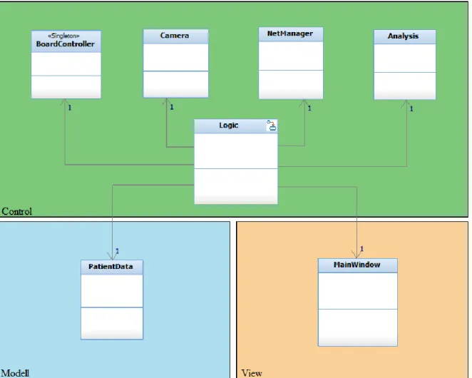
The programming is based on the following software engineering results. The different physical com-ponents that are used in the application could be realised each with its own class. They will be ex-plained lately. Then the Model-View-Control pattern could be applied. The result is a patient data class and a logic class. These classes decouple the data, the user interface, and the systems behav-iour. The classic MVC-pattern says the controller modifies the model, the model notifies the window and the window creates events in the controller. In this application, there is no relation between the model and its view because the logic decides which data to show on the display.
Figure 4 class diagram MVC-pattern
The reason why the logic has pointers to objects of all classes is because it acts as a factory. This means objects are initialised and connected by the logic.
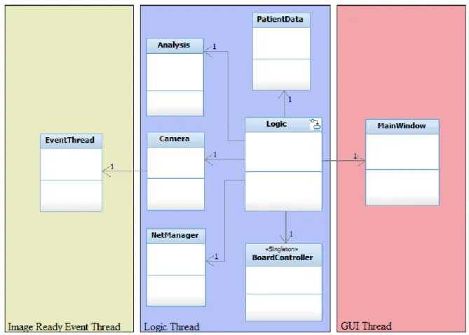
Nicolas Marty 10. Juli 2015 page 9 of 30 To keep the application responsive and execute the logic in the background a separate thread for the user interface is created. The camera’s live view needs also an own thread. While the physical cam-era is running in video capturing mode, it is creating events whenever an image is ready to read. The event thread listens to the physical camera and notifies the camera object if an image is ready to read. The camera reads the image from the memory and sends it to the mainwindow.
Figure 5 class diagram orderd by threads
The communication between threads is asynchronous. Qt’s Signal-Slot mechanism is made exactly for asynchronous communication. Data can be passed safely from one thread to another using this mechanism. The camera can emit the image as a signal and because this signal is bound to a slot in the mainwindow, the image will arrive to the mainwindow’s thread and there it will be displayed. The work of connecting signals and slots is done during the initialisation, right after the objects are created. Another big advantage of signal-slots is that objects do not need a pointer to the object where the data is sent to. A signal is emitted regardless of a slot is connected or not. This behaviour decouples the classes and increases the program’s modularity. Classes can be exchanged entirely without affecting the rest of the program (except the factory). To show clearly the signal flows, an-other diagram is added bellow.
Nicolas Marty 10. Juli 2015 page 10 of 30
Figure 6 signal flow diagram
The colours correspond to the threads where the objects of these classes are living in. The Signal-Slot mechanism can also be used to call methods asynchronously on the same thread. The three purple signals are used this way. The trigger- and lowBattery-signal are created on a low level interruption. The event-signals are created by the state machine itself.
Nicolas Marty 10. Juli 2015 page 11 of 30
Logic
The most important class is the Logic. It implements a state machine that is responsible for the pro-grams behaviour. The statechart below shows each state and the events that lead to the next state.
Figure 7 system state chart
Nicolas Marty 10. Juli 2015 page 12 of 30 The program starts with the initialisation. After that the program goes into the idle state. In this state multiple actions can be done. If the trigger button is pressed during idle state a series of tures is taken without patient context. These pic-tures are uploaded to a general folder on the serv-er. A click on the Advanced button shows additional functions. Within the advanced functions, the preview wavelength can be selected manually, the calibration can be started and the homogeneity filter can be activated or disactivated.
Figure 9 screenshot of ilde state (advanced mode) Figure 10 screenshot of free picture state
A click on select patient starts the process of taking patient pictures. To select a patient a 4 digit ID must be entered. Then the region of the mole must be chosen. As soon as the selections are done, a patient preview appears. The trigger button leads to the patient picture state where the pictures are taken, analysed and stored in the RAM.
Figure 11 screenshot of select patient state Figure 12 screenshot of select region state
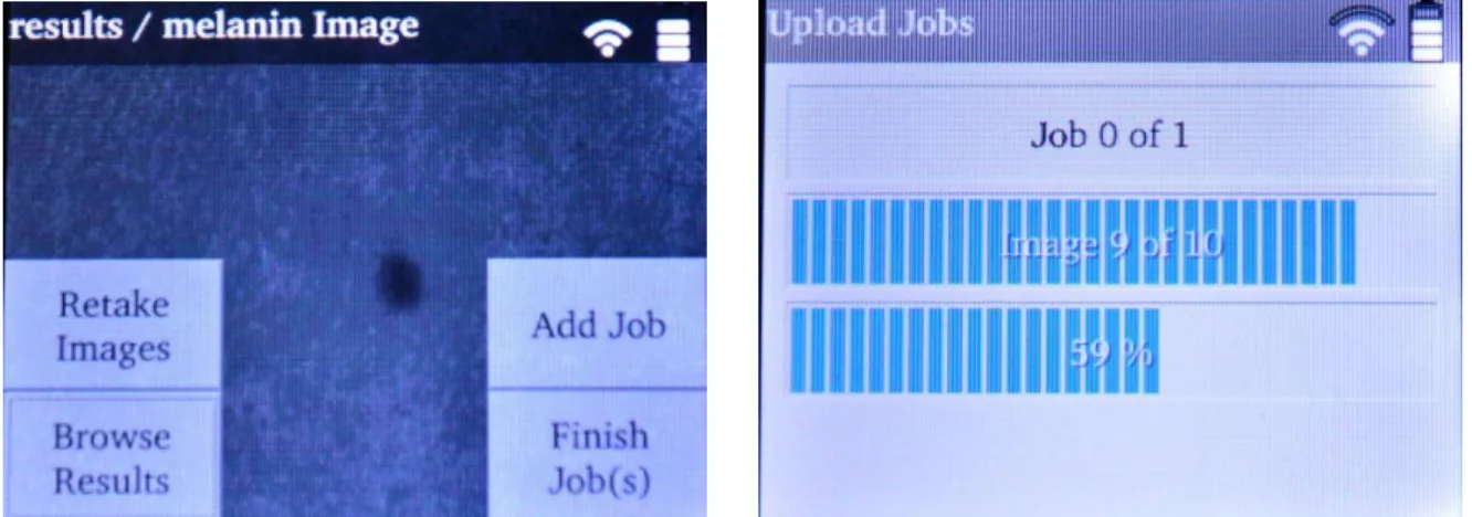
Nicolas Marty 10. Juli 2015 page 13 of 30 The next state shows the results. The picture can be retaken if necessary. If there are more moles to scan, jobs can be added. In the end all the images in the RAM with the patient data are uploaded to the server where they can be accessed with the Web Application.
Figure 13 screenshot of show results state Figure 14 screenshot of transmit jobs state
MainWindow
The mainwindow is the graphical class that implements all views, buttons, etc. The mainwindow itself does not implement logic. Button clicks are transmitted to the logic class where the action is processed. The mainwindow uses Qt’s QStackedLayout feature to organise all the different screens. During the initialisation of the mainwindow all screens are constructed. The logic class selects the widget to display for each state.
Camera
The camera class makes use of the ueye API to access and control the cam-era. The camera is initialized at the program start. As soon as the camera can be accessed the picture and video memory are allocated. The camera class implements two imaging modes: A low resolution, high framerate video mode used during liveview and a high resolution photograph mode used to take raw pictures of moles. If switching from video mode to photo-graph mode, the EventThread is stopped, the image capturing is changed to trigger mode, the resolution is changed and the image memory is changed. The camera class implements also methods to let the logic change easily the exposure time and take a picture on demand.
Figure 15 stack layout principle
Figure 16 camera includes uEye API
selectPatient- Screen
Nicolas Marty 10. Juli 2015 page 14 of 30
Analysis
To make a meaningful analysis a calibration of the system is important. There are two calibration steps. The first one standardizes the cameras sensitivity for each wavelength. If taking pictures of a calibration surface, images of each wavelength must have the same brightness level (NORM). This is achieved by setting the correct exposure time. The algorithm to get the exposure time works approx-imatively and is explained on the following picture.
brightness [%]
Steps [-] NORM
Initial exposure time to short To long exposure time
Match
Figure 17 calibrate exposure time algorithm
The second calibration step treats the problem of inhomogeneous illuminated areas caused by the different lightning. For each set of LEDs a filter file is created. The filters are applied for each raw image taken by the camera. Michael Schmid worked already on the homogeneity filter in his bache-lor thesis last year. The algorithm could be rewritten to work on the Raspberry Pi. The illumination is already very homogenous without filter.
Figure 18 image without homogeneity filter Figure 19 image with homogeneity filter
The function to detect melanin could be taken from the earlier project too and has been reimple-mented on the Raspberry Pi.
Another analysis method calculates a coloured image out of the raw images with wavelengths 470nm, 520nm and 610m. A pixel is consists of 3 bytes. One for red, blue and green. The coloured image is created by setting the value of 470nm as blue part, the 520nm as green part and the 610 nm as red part for each pixel. This algorithm is probably not that useful for a doctor but there is an im-pression of the capabilities of multispectral illumination.
Nicolas Marty 10. Juli 2015 page 15 of 30 The analysis class offers a method called dynamicAnalysis(). The logic calls this method during runtime. The function takes a series of raw images and returns a map of result images. A map con-sists of key and value pairs. In this case the key is from type string and contains the name of the anal-ysis and the value is the result image. The function is named dynamic because the number of re-turned result images can vary. If analysis methods are added in the future the programmer must only work on the analysis class. Analysis methods can be added to the dynamic analysis function and the rest of the program can be left untouched.
NetManager
The network manager is responsible to up-load the images to a server. It is also the inter-face to the web application. The following flowchart shows an excerpt of the program that works with a patient. The blue marked actions involve requests to the server.
At the beginning a patient must be selected. Because the Raspberry Pi’s touchscreen is small there are only 10 number buttons to enter the patient’s number. This number con-sists of 4 digits. It corresponds to a patient in the database. If the fourth digit is entered the getPatientRequest() is sent to the server. The patient information is sent back in the re-sponse. If the patient number was incorrect the response contains an error and the next steps are cancelled.
The next step creates a new episode of care. The episodes of care are used in the web ap-plication to show the history of a specific mole. This is done by sending the createEpi-sodeRequest(). The response contains the episode id. It is stored in the patient data. As soon as the images are taken, the data can be uploaded. They must be uploaded to a specific directory. The createDirectoryRe-quest() makes the server application create the image directories out of the region and episode. The paths are sent back as response.
The uploadResultsRequests() takes all the information from the patient data and sends it to the serv-er. The data (except the images) transferred to and from the server is in form of json strings.
Get Patient Patient Data Select region and subregion Take pictures & do analysis Upload Job(s) Create Episode
X
Create directoryX
Nicolas Marty 10. Juli 2015 page 16 of 30
PatientData
The PatientData class stores the images in context with patient information. The data is set during a job and cleared after a successful upload.
BoardController
The BoardController uses the wiringPi library to create an abstraction layer of the signals connected to the GPIO Pins of the Raspberry Pi.
There are two interrupt routines. One creates a triggerEvent if the trigger-Button is pressed and the other one creates a lowBatteryEvent if the PowerManager raises the corresponding signal.
The BoardController implements a method to send the shutdown signal to the PowerManger and to poll the battery level. It implements also the methods to turn on/off the illumination and to change the wavelengths.
TouchTransform
Qt has touchscreen support. If a touch device can be found at application
start, touch events will be created. Unfortunately there is a bug in the touchscreens driver or in Qt and the coordinates received with a touch event are completely wrong. Luckily, a touch event has a method called rawScreenPositions(). The coordinates read from this method are correct but don’t consider the screen orientation. The class TouchTransform acts as event filter that modifies all in-coming touch events using the rawScreenPosition() method.
Variables
The variables file contains no class but many configuration parameters used at different places in the program. For example the server URL and the GPIO pin layout are defined in this file.
4.3.2 Energy Management
Battery choice
There are many existing battery technologies. Each technology has its own pros and cons. Lead Bat-teries have a huge capacity but are heavy and bulky. NiCd batBat-teries are cheap but an old technology and known for their memory effect. The newer NiMh batteries are also cheap but they do not suffer the memory effect. Li-Ion batteries are expensive but they have a high capacity, low self-discharge and if well treated, a long lifetime. There is another Lithium based technology, called Li-Polymer. These batteries are mainly used in remote controlled planes because they are very light weight. They are very sensitive to temperature changes, impacts and need good care.
At this point Li-Ion or NiMh technology fits best for the project but there are still some more facts about these two types.
Li-Ion batteries don’t need maintenance. The user of the final device does not have to cycle the bat-teries as he would do it with NiMh nor must he replace them. At least until a very high number of charge cycles is reached and the capacity becomes significant lower as at the beginning when the battery was new. Then the self-discharge rate of Li-Ion batteries is lower than NiMh. The only ad-vantage left for NiMh is the price.
Figure 21 Board-Controller includes
Nicolas Marty 10. Juli 2015 page 17 of 30 One Li-Ion cell has a nominal voltage of 3.6V and if fully charged 4.2V. The Raspberry Pi needs 5V, so just a one-cell Li-Ion battery with a step-up converter can be used to power the Raspberry Pi.
Li-Ion batteries have a simple charging algorithm consisting of 2 phases. The charging cycle begins with a constant current phase. As the name says, during this phase the battery is charged with a con-stant current. If the voltage of the cell reaches 4.2V phase 2 begins. Phase 2 is called concon-stant voltage phase. The charge controller maintains the 4.2V and decreases the charge current slowly until it reaches the cut-off point. This point is set at 10% of the constant charging current. Setting the point lower charges the battery to a higher capacity at the cost of lifetime.
Figure 22 Li-Ion charging algorithm [2]
There are integrated circuits that implement this charging algorithm. This makes the development of an electronic circuit much easier and faster.
Li-Ion batteries offered the most advantages so this technology is used in this project. In particular a single-cell Li-Ion battery with a capacity of 2900mAh and a nominal voltage of 3.6V was chosen.
Nicolas Marty 10. Juli 2015 page 18 of 30 Supercapacitors
Another idea was to use super capacitors as energy storage. Supercapacitors have a high capacity usually >100F. They are used in Formula 1 in the KERS Kinetic Energy Recovery System. They are ca-pable of delivering very high power and can be charged very fast. The number of charge cycles is higher than one million. All these advantages make supercapacitors expensive. Supercapacitors have little electrical strength. The voltage at which a super cap can be charged is usually below 3V. The energy stored can be calculated as follows.
To run the Raspberry Pi for half an hour at full load it consumes the following amount of energy:
To make an approximate calculation a current of 1A was taken.
A supercapacitor that is capable of storing this amount of energy is very expensive. To make a con-crete estimation a supercapacitor from Kemet was taken. The capacitor is rated 3000F / 2.7V and costs approx. 175.- SFr. at farnell. The dimensions of this capacitor are 60.7 x 144 mm (D x L).
An estimation of run time can be calculated with a combination of the two formulas above.
The biggest advantage of a super capacitor – its rapid charge and discharge times – cannot be used. An AC/DC USB adapter delivers 2A but the super cap could be charged with 145A (1s peak 2200A). The discharge rate is also far below the rated current.
Figure 24 Kemet Supercapacitor [1]
UPS
A Raspberry Pi UPS (uninterrupted power supply) is not convenient for this project as the main pur-pose of a UPS is to power the Raspberry Pi during a short period of time where the cable power sup-ply is turned off. Further, these systems are mounted usually on the GPIO Header of the Raspberry Pi where the display is already placed. Any solution to use both UPS and display would lead to a too large casing.
Nicolas Marty 10. Juli 2015 page 19 of 30
Figure 25 Supercapacitor UPS for Raspberry Pi [1]
Electronics General function
Raspberry Pi, Camera & Lightning Charger & Load sharing Battery Step-Up DC/DC Converter Linear Regulator Power Switch Voltage Measure PIC Microcontroller USB 5V 5V @ 1.75A max. 3V @ 150 mA max. PowerOn Button
3V Low Power circuitry
Raspberry Pi GPIO
5V High Power circuitry 3.3V
Power Path Signal Path Indicator
LEDs
Nicolas Marty 10. Juli 2015 page 20 of 30
Charger & Load sharing
An integrated circuit provides the functions of charging the battery and sharing the system load be-tween the battery and the external power supply. The IC uses the CC-CV charge algorithm mentioned above. The constant charge current and the cut-off current can be determined by two resistances. The charger allows a maximal charge current of 1A. This is within the battery specifications. Three status signals are connected to the Microcontroller. They offer information about the state of the charger. These signals will be used later in the programming. The integrated circuit has also a load sharing function. With this function a device can be charged while it is in use. To use this function all the current must pass through the charger. In other words, the battery must only be connected to the charger, nowhere else. The maximal, shared current is 1.65A according to the datasheet. At high currents the charger is going to heat up until it activates the thermal protection (shutdown). The maximal current drawn from the battery is about 1.25A if the Raspberry Pi with strongest illumina-tion activated. This current leads already to overheat. A small cooler glued on the IC with thermal compounds did not solve the problem. The battery must be connected directly to the power switch. The high currents do not pass the charger anymore and the problem is solved. The load sharing func-tion can just be used to power the microcontroller. If the device is placed on the docking stafunc-tion to charge while the Raspberry Pi is running, the power switch is instantly turned off. That’s because the charger assumes that all the current passes through it. The system can be damaged if this condition is not met.
DC/DC step up converter design
The step-up converter is able to convert the battery voltage going from 3V to 4.2V to the Raspberry Pi’s 5V. The converter can output a maximal current of 2.1A. It is in form of an integrated circuit. It has a fixed output voltage of 5V. This is more accurate than an adjustable converter because of pre-cise internal resistances. The worst case scenario where the battery voltage is 3V and the Raspberry Pi draws the maximal current of 768 mA (measured during semester project) leads to a battery dis-charge current of at least 1.28A according to the law of energy conservation.
The maximal battery discharge current is 2.95A. A current of 1.28A is far from this limit. Neverthe-less, the system should not draw more than 1.75A.
Linear Regulator
This regulator is designed to output 3V for low power devices. It has a very low quiescent current. The microcontroller will be powered from this regulator even if the Raspberry Pi in the high power branch is turned off.
Microcontroller
Because the microcontroller is powered all the time by the battery it must draw very little current if the device is not plugged in to a power supply. The choice fell on a PIC18LF25K22. It draws a minimal current of only 20nA in sleep mode. Further, there is an existing Execution Framework written in C (HEVS Picco-XF) that works well on this PIC and if implemented, simplifies many software develop-ment steps.
Nicolas Marty 10. Juli 2015 page 21 of 30
Voltage measure
The voltage decrease of Li-Ion batteries is almost proportional to the charge. This behaviour can be used to simply calculate an approximate charge-percentage. This percentage is used to show a bat-tery symbol on the display. A voltage divider is powered by the batbat-tery allows measuring the voltage. It is designed to output 3V if the battery fully charged is at 4.2V. Because the microcontroller is pow-ered by 3V, the reference voltage for analogue-digital conversion is also at 3V. A full battery will therefore result in the highest conversion value.
The voltage measure is also used for safety reasons. The Li-Ion battery must not be deeply dis-charged, as this will damage the battery. If the voltage drops under 3V the microcontroller will send an emergency signal to the Raspberry Pi to indicate that it must be shut down and recharged.
Power-Manager Device Operation
The result of the electronics and the microcontroller’s software is a power manager device for the Raspberry Pi. Its operation is described in this chapter based on the following, common scenario: The Raspberry Pi is turned off and the power supply is disconnected, the microcontroller waits in sleep mode until the power button is pressed. As soon it receives the power button interruption it will turn on the power switch and the DC/DC converter begins to work and power the Raspberry Pi. From now, the microcontroller takes periodically samples of the battery voltage to calculate an esti-mated charge percentage. The Raspberry Pi is going to read these samples from time to time via UART. The device can be forced to turn off by pressing the button for 5 seconds. This should normally not be used because the Raspberry Pi will create an interruption that indicates its shutdown process. After a delay the microcontroller will turn off the Raspberry Pi’s power switch safely and go to sleep mode. Then a power supply is plugged in to the charger and it will start to recharge the battery, the microcontroller will wake up and indicate the charge state with 3 LEDs.
Off
Running Charging
Plug in / unplug On / off Plug in
Figure 27 PowerManager state chart
Generally, the device can be in three different states. The transitions from one state to another are based on events that are created either if the Raspberry Pi turns on/off or the power supply is plugged in/out. Each state turns different peripherals of the PowerManager on or off, to consume the less energy. The Raspberry Pi can be regarded as the main peripheral. The different states con-tain the following actions:
Nicolas Marty 10. Juli 2015 page 22 of 30
Off
o Raspberry Pi Power-Switch turned off o ADC turned off
o Charger Status-Signal pull-up-resistors not powered o Indication LEDs turned off
o UART device turned off
Running
o Raspberry Pi Power-Switch turned on
o ADC turned on & periodic measurement of battery voltage o Charger Status-Signal pull-up-resistors not powered o Indication LEDs turned off
o UART device turned on & waiting on request
Charging
o Raspberry Pi Power-Switch turned off o ADC turned off
o Charger Status-Signal pull-up-resistors powered & polling status periodically o Indication LEDs turned on & showing charge state
o UART device turned off Connection to Raspberry Pi
Figure 28 Raspberry Pi power supply protections [1]
1. 2A Fuse 2. Ideal Diode 3. ESD Protection
The power supply is ensured by connecting cables to the 5V pin of the Raspberry Pi’s pin header. The 2A fuse and the ideal diode are bypassed. These protections are not important because the maximal current draw was measured and is below 2A. The Raspberry Pi is built into the casing and the USB connector is hidden. This another reason why it does not matter to bypass the fuse and the ideal diode.
2
1
Nicolas Marty 10. Juli 2015 page 23 of 30 Tests
The current draw in the “Off” state was measured to be sure that the device will not discharge signif-icantly while it is not used. Therefore, an ampere meter was placed in the circuit as shown on the picture below.
battery system
A
I
totI
totFigure 29 current measurement
The measure showed a current draw of 85µA during sleep mode. The fully charged battery has a capacity of 2900mAh. Theoretically, the discharge time would be more than 3 years.
The period of use was measured while testing the whole system in the end of the project. A period of use of more than 1h could be achieved.
The time to charge an empty battery is about 3h 30min. The time has been measured multiple times and 3h 30min turned out to be the average.
4.3.3 Camera & Illumination
The camera and the optics are taken from the earlier project. The illumination could also be reused with some modifications. The schematic below on the left describes the lightning electronics and the interface to the Raspberry Pi.
395nm 428nm 470nm 520nm 570nm 610nm 740nm 880nm
LED rotation
Figure 30 LightManager electronics block diagram Figure 31 LED rotation
Only one wavelength can be active at the same time. With the next and previous signal, the control-ler rotates to the next or previous wavelength. The microcontrolcontrol-ler draws only little current because the LEDs are powered from the 5V supply. The microcontroller supply pin is connected directly to a GPIO pin of the Raspberry Pi. To turn off the illumination the Raspberry Pi simply turns off the micro-controller. The LEDs cannot be driven directly by the Raspberry Pi because there are to less GPIO pins. LEDs LEDs microcontroller LEDs 5V 3.3V 8x next previous
Nicolas Marty 10. Juli 2015 page 24 of 30
Figure 32 assembly of illumination panels
The illumination is made of 4 panels, each with LEDs of 8 wavelengths. Some wavelengths need mul-tiple LEDs per panel to shine bright enough. The panels fit exactly into the container.
Figure 33 illumination 520nm
The LEDs do not point directly on the skin. The reflections are decreased due to this reason and the illumination is very homogenous.
Nicolas Marty 10. Juli 2015 page 25 of 30
4.3.4 Casing
The development of the casing was based on the experience of the earlier versions and two im-portant ideas. The first one is that the electronic components should be stacked on top of each other to save space. The second idea was to create a casing with two separate halves. The system can be mounted and tested in one half and closed in the end. The PCB shapes of the light-manager and the power-manager have been fabricated to fit exactly into the casing.
Figure 34 device interior
1. Illumination container 2. Adjustable lens 3. TriggerButton
4. Camera 5. LightManager 6. PowerManager
7. Battery 8. Raspberry Pi 9. WLAN Dongle
Two contacts allow putting the camera on a docking station to recharge.
Figure 35 contacts for docking station
9
1
2
3
4
5
6
7
8
Nicolas Marty 10. Juli 2015 page 26 of 30
Figure 36 docking station Figure 37 spring-suspended pins
The docking station contains a heavy metallic ring to avoid tipping the camera while it is not in use. The electrical contacts are ensured by two spring-suspended pins that press against the camera. Any usual 5V/1A AC/DC wall adapter with micro-USB plug can be used to power the docking station.
Nicolas Marty 10. Juli 2015 page 27 of 30
5 Results
The system was tested in the end of the project on different subjects. It can take multispectral imag-es, analyse them and send the data to a server using WLAN. It implements the doctor’s use case where images in context with data of a patient are uploaded to a web application. The image acquisi-tion can be calibrated and a homogeneity filter can be applied. The melanin analysis was imple-mented but not tested. An additional RGB image is calculated. The battery keeps the device running for over 1 hour. The recharge time is about 3:30 hours.
Figure 39 Device in use Figure 40 patient data uploaded to web application
Nicolas Marty 10. Juli 2015 page 28 of 30
6 Future Improvements
The software does not handle errors if the WLAN connection fails. This should be the first point to work out in the future.
The method to detect the melanin must be tested.
At the moment the wireless configuration must be done manually in the linux console. There should be implemented an easier way to connect the device to a new wireless network.
The assembly of the system in the casing is very difficult due to little space. The fixations for the PCBs and the camera must be improved.
It works best if the Raspberry Pi is programmed via a network cable. To be able to connect this cable to the assembled system a port in the casing should be added which can be closed with a rubber stopper.
The assembly of the illumination panels is a nasty work. The illumination should be fabricat-ed using flexible or semi-flexible PCBs.
Figure 42 Euro Circuits semi-flexible PCBs [1]
7 Conclusion
The development of the software took a big part of the time. To get to know the camera application interface took much time because of the vast amount of functions and settings. Luckily, the docu-mentation is very well done and helped a lot. The camera driver runs stable on the Raspberry Pi. The Raspberry Pi itself has a great community, therefore a lot of information about configuration can be found in the internet. I became a real Raspberry Pi fan during this project not least because Qt works like a charm on it. The possibility to use Qt was great and solved a lot of problems already at the start. Only the capacitive touchscreen caused some trouble because the coordinates of touch events were not received correctly without a workaround. Perhaps a future update of Qt or the display driv-er solves the problem. I enjoyed the work of developing a web intdriv-erface in coopdriv-eration with Andreas Imsand because he is a friend of mine in private life.
In the end there was no more time to implement an error handling for the scenario where the WLAN connection fails. The test of the melanin analysis could not be done also as a consequence of time constraints. The algorithm is the same as in an earlier project and because the illumination, camera and optics kept the same it is just a matter of time to get the melanin analysis working properly.
Nicolas Marty 10. Juli 2015 page 29 of 30 The selection of the proper battery type for this project required quite some time of research into battery technologies. The choice of Li-Ion batteries had the big advantage of already existing and uncomplicated integrated circuits for recharging.
The fabrication of the PCBs and the casing took place in the second half of the project. There were a lot of discussions about the shape of the PCBs and the casing, how to connect the PCBs and where to place them in the casing. Soldering the components on the different PCBs and assembling the system took quite some time and the first power-on of the system was an exciting moment. Unfortunately, the charge & load sharing IC easily overheated if the Raspberry Pi with the camera and illumination were turned on. A cooler was glued on top of this IC with thermal compounds. This did not solve the problem. The electronics had to be reworked and luckily, the power PCB could be modified without fabricating a new one.
The final tests were successful and images could be taken, analyzed and transmitted to the server. There were ups and downs, successes and failures but in the end it was great experience and I am not likely to change the business.
8 Sources
[1] Product image of manufacturer
[2] Battery university: http://batteryuniversity.com/
[3] Supercapacitors: https://de.wikipedia.org/wiki/Superkondensator
[4] UPS: https://de.wikipedia.org/wiki/Unterbrechungsfreie_Stromversorgung [5] Bachelor thesis & sources, Michael Schmid, 2014, on CD
[6] Component datasheets, on CD
[7] Source code ueye demoprogram , on CD [8] Source code HEVS picco-XF, on CD
[9] Li-Ion additional charging tips: http://www.powerstream.com/li.htm [10] Raspberry Pi: https://www.raspberrypi.org/
[11] Qt: http://www.qt.io/developers/ [12] uEye documentation, on CD
[13] Semester project , Nicolas Marty, 2015
[14] Hardware specifications, semester project [13]
9 Appendix
[A] Setup Raspberry Pi [B] Pin Header Layout [C] Materials List
[D] Schematics & PCB PowerManager [E] Schemactis & PCB LightManager
[F] Schematics & PCB illumination panel, indication LEDs, USB adapter [G] Source code qt main application
[H] Source code PowerManager [I] Source code LightManager
Nicolas Marty 10. Juli 2015 page 30 of 30
10 Signature
Nicolas Marty 06. Juli 2015 Seite 1 von 13
Appendix A – Setup Guide
Raspberry Pi and Development
Environment
Nicolas Marty 06. Juli 2015 Seite 2 von 13
Content
Introduction ... 3 Raspberry Pi 2 Setup ... 3
Raspbian OS ... 3 Adafruit 2.8” PiTFT+ Capacitive Touchscreen (Product-ID #2423) ... 4 uEye Camera ... 6 WLAN ... 6 Power Saving ... 7 Installing the Splashscreen ... 7 Automatic Login & Application Start ... 9 Tweak Performance ... 9
Setup Development Environment ... 9
Ubuntu Virtual Machine ... 9 Setup Cross Compilation ... 10 Configure Qt Creator ... 11
Nicolas Marty 06. Juli 2015 Seite 3 von 13
Introduction
In order to use a Raspberry Pi for my bachelor thesis there are a couple of things to install and configure before the Qt Application can be executed. This document describes step-by-step the Raspberry Pi 2 Setup and the QtCreator configuration to cross-compile on Raspberry Pi for this specific project.
Raspberry Pi 2 Setup
Raspbian OS
Prerequisites
You need a Windows PC, MicroSD-Card, CardReader and of course a Raspberry Pi B+.
Download and unzip newest Raspbian Image from http://www.raspberrypi.org/downloads/
Download and install newest Win32 Disk Imager from http://sourceforge.net/projects/win32diskimager/
Installation
Write Image to SD-Card
1. Connect MicroSD-Card to PC. 2. Start Win32 Disk Imager.
3. Select raspbian image from your download directory, e.g. ./2015-02-16-raspbian-wheezy.img 4. Select proper device (SD-Card drive letter), e.g. [J:\]
5. Write image to SD-Card using the “write” button, this process takes a couple of minutes. Booting the Raspberry Pi for the first time
1. Insert MicroSD-Card into RPi.
2. Make sure a monitor and a keyboard is connected. (SSH can be used also, raspi-config must be started manually)
3. If everything is ok, system should open the raspi-config. 4. Select the following options:
a. Expand Filesystem > ok
b. Internationalisation Options > Change Keyboard Layout > Generic 105-key (Intl) PC >
desired language > …keep default options… > ok
c. Advanced Options > SPI > yes > ok > yes > ok (enable SPI on startup, used by PiTFT) d. Advanced Options > Hostname > Enter a unique hostname
e. Finish, reboot.
5. After reboot, login with user pi and update the device with following command: sudo apt-get update then sudo apt-apt-get upgrade and last but not least sudo rpi-update 6. Set the password for the root user. Root is used later to execute wiringPi. Enter following
commands: sudo –i and then passwd, set password to 123456
7. Now the initial config is done, time to backup. Shutdown system with following command: sudo shutdown –h now
Create Backup Image
1. Unplug SD-Card from RPi and connect it to PC. 2. Start Win32 DiskManager.
3. Select a destination and filename for the backup, e.g. ./bkp_raspian_raspi-configured.img 4. Select proper device (SD-Card drive letter), e.g. [J:\]
Nicolas Marty 06. Juli 2015 Seite 4 von 13
Adafruit 2.8” PiTFT+ Capacitive Touchscreen (Product-ID #2423)
Prerequisites
In addition to Raspbian OS prerequisites you need a network cable with connection to the internet.
Mount PiTFT on RPi 2.
Optional: Download PuTTY (used for SSH remote connection)
http://www.chiark.greenend.org.uk/~sgtatham/putty/download.html
The original adafruit driver is currently not working, installing it results in RPi not booting anymore.
Manual Installation – OLD (see chapter Easy Install)
Kernel Update
1. Execute following command: sudo rpi-update
This will download and install the newest kernel + drivers. This update contains already all drivers who make the PiTFT working.
2. After the installation reboot the RPi2 with sudo reboot
Setting up the display
1. Open /boot/config.txt with following command : sudo nano /boot/config.txt
2. Add these lines at the end of the file: dtparam=spi=on
dtoverlay=pitft28-resistive
These lines give parameters to the already installed display driver
3. To show the graphical XWindows interface on the PiTFT, the correct framebuffer must be selected. In order to do this, open the 99-fbturbo.conf file with the command:
sudo nano /usr/share/X11/xorg.conf.d/99-fbturbo.conf 4. Change /dev/fb0 to /dev/fb1
PiTFT is now selected. Setting up the touchscreen
5. Open /etc/modules with : sudo nano /etc/modules 6. Add this line at the end of the file:
stmpe-ts
This will load the kernel module (driver) for the touchscreen 7. Create a devicemanager rule file for the touchscreen.
sudo nano /etc/udev/rules.d/95-stmpe.rules
8. Because the touchscreen event nr can change if keyboard and mouse are attached, it must be mapped to a constant event name, called touchscreen. Add the following line to the file and save&exit.
SUBSYSTEM=="input", ATTRS{name}=="stmpe-ts", ENV{DEVNAME}=="*event*", SYMLINK+="input/touchscreen"
9. Remove and reinstall touchscreen module
sudo rmmod stmpe_ts; sudo modprobe stmpe_ts
10. Test if the mapping worked with: (should look like /dev/input/touchscreen -> eventX)
Nicolas Marty 06. Juli 2015 Seite 5 von 13 11. Download calibration tools:
sudo apt-get install evtest tslib libts-bin 12. To view touchscreen events in realtime execute:
sudo evtest /dev/input/touchscreen 13. Run the calibration with:
sudo TSLIB_FBDEVICE=/dev/fb1 TSLIB_TSDEVICE=/dev/input/touchscreen ts_calibrate
Activate console on PiTFT 14. Execute command:
sudo nano /boot/cmdline.txt
and add fbcon=map:10 at the end of the line Rotate display
1. To rotate the display modify the boot config file sudo nano /boot/config.txt
2. Modify the line dtoverlay, the parameter rotate changes the orientation dtoverlay=pitft28r,rotate=90,speed=32000000,fps=20 Possible values are:
0, portrait, with the bottom near the USB jacks
90, landscape, with the bottom near the headphone jack
180 portrait, with the top near the USB jacks
270 landscape, with the top near the headphone jack
Easy install – USE THIS
1. Add adafruit repository to the system
curl -SLs https://apt.adafruit.com/add | sudo bash sudo apt-get install raspberrypi-bootloader
sudo apt-get install -y adafruit-pitft-helper 2. Start installation script
sudo adafruit-pitft-helper -t 28c
3. Would you like the console to appear on the PiTFT display? n 4. Would you like GPIO #23 to act as on/off button? n
5. Activate display to show graphical interface: export FRAMEBUFFER=/dev/fb1
6. If the graphical interface is to be started via ssh, the following environment variable must be set:
export DISPLAY=:1
7. Reboot, login and execute startx to start the graphical interface. 8. Display and touch screen should work.
9. (Optional) calibrate display: see section above
Turn display on/off
15. Create device link with command:
sudo sh -c "echo 508 > /sys/class/gpio/export" 16. Set GPIO#508 as output with:
sudo sh -c "echo 'out' > /sys/class/gpio/gpio508/direction" 17. Turn on/off with commands:
sudo sh -c "echo '1' > /sys/class/gpio/gpio508/value" sudo sh -c "echo '0' > /sys/class/gpio/gpio508/value"
Nicolas Marty 06. Juli 2015 Seite 6 von 13
XWindows error message fix
When starting XWindows, there will probably appear an ugly error message. This is because of a bug in the actual Raspbian Image for RPi2. To get rid of this message open a terminal (in XWindows) and execute:
lxsession-edit
Uncheck LXPolKit in the dialog box and reboot RPi.
uEye Camera
Prerequisites
Copy uEyeSDK-[Versionsnummer]-ARM_LINUX_IDS_[Setuptyp].tar on a usb stick and mount it on RPi 2.
Installation
1. Mount usb drive with following commands: sudo mkdir /media/usbdrive
sudo mount /dev/sda1 /media/usbdrive 2. Copy files to your home directory:
cp uEyeSDK-[Versionsnummer]-ARM_LINUX_IDS_[Setuptyp].tar ~ 3. Unpack archive on target system using:
sudo tar xvf uEyeSDK-[Versionsnummer]-ARM_LINUX_IDS_[Setuptyp].tar -C /
4. Execute Setup-Script:
sudo /usr/local/share/ueye/bin/ueyesdk-setup.sh 5. unmount usb drive with these commands:
sudo umount /media/usbdrive sudo rmdir /media/usbdrive
6. To make the demoprogramm work finally, the libqt3support library must be installed with following command (do not install until you really want to test the demopgrogram): sudo apt-get install libqt4-qt3support
7. Start demoprogram with the command: sudo ueyecameramanager
the demoprogram must be started while running XWindows (startx)
WLAN
Prerequisites
Plugin WLAN Dongle
Configuration
1. Get a list of the available wireless networks using the following command: sudo iwlist wlan0 scan
2. Open the wpa_supplicant.conf file with the following command, this file contains the connection information to your desired WLAN:
sudo nano /etc/wpa_supplicant/wpa_supplicant.conf 3. Add the following at the end of the file:
If you are using WPA-PSK (e.g. home network) add these lines: network={ ssid="YourSSID" psk="password" key_mgmt=WPA-PSK id_str="home" }
Nicolas Marty 06. Juli 2015 Seite 7 von 13 If you are using WPA-EAP (e.g. HEVS enterprise network) add these lines:
network={ ssid=”secure-hevs” proto=RSN key_mgmt=WPA-EAP pairwise=CCMP auth_alg=OPEN eap=PEAP identity=”username” password=”password” id_str="enterprise" }
4. If you are suffering problems enter the following command to get a debug message: sudo wpa_supplicant -i wlan0 -D wext -c
/etc/wpa_supplicant/wpa_supplicant.conf –d i
Make sure the RPi is connected and received an IP-Address. Use this command to show the network interface information and look at interface wlan0:
ifconfig
Power Saving
The Raspberry Pi does not have a sleep mode. There is just the possibility to suspend the monitor. The suspend time can be set with the following command: (it will be reset after a reboot, this function has not been used and serves only as information)
setterm -blank [minutes]
Installing the Splashscreen
To hide all the “scary” linux startup outputs from the end user a nice splashscreen must be displayed. 1. First of all, install fbi: sudo apt-get install fbi
2. Copy your custom splash image to /etc/ and name it "splash.png".
Example command: rsync -avz ~/splash.png root@rpi2:/etc/splash.png 3. Create a script called asplashscreen in /etc/init.d/. Enter the following code:
#! /bin/sh
### BEGIN INIT INFO
# Provides: asplashscreen # Required-Start: # Required-Stop: # Should-Start: # Default-Start: S # Default-Stop:
# Short-Description: Show custom splashscreen # Description: Show custom splashscreen ### END INIT INFO
do_start () {
/usr/bin/fbi -T 1 -noverbose -a /etc/splash.png exit 0
}
Nicolas Marty 06. Juli 2015 Seite 8 von 13 start|"")
do_start ;;
restart|reload|force-reload)
echo "Error: argument '$1' not supported" >&2 exit 3 ;; stop) # No-op ;; status) exit 0 ;; *)
echo "Usage: asplashscreen [start|stop]" >&2 exit 3
;; esac :
4. Then make that script executable and install it for init mode rcS: chmod a+x /etc/init.d/asplashscreen
sudo insserv /etc/init.d/asplashscreen
5. The splashscreen will not appear if the device is rebooted now. That’s because the startup is displayed on the framebuffer fb0 from the HDMI output. And not the fb1 from the PiTFT. The solution for this is to install a framebuffer mirroring tool.
Install fbcp as follows:
sudo apt-get install cmake
git clone https://github.com/tasanakorn/rpi-fbcp cd rpi-fbcp/
mkdir build cd build/ cmake .. make
sudo install fbcp /usr/local/bin/fbcp
6. Open the asplashscreen file again and go to the line just after do_start(){ 7. Enter the following expression: /usr/local/bin/fbcp &
This will start the framebuffer mirroring tool. The “&” makes it run in the background.
8. The fb0 output must be adjustet to match the settings of the fb1. Open /boot/config.txt and search for the commented lines:
#hdmi_group=1 #hdmi_mode=1
Change these lines and add the following lines right below, in the end it must look like this: hdmi_group=2
hdmi_mode=87
hdmi_force_hotplug=1