Algorithms for Planning and Executing
Multi-Roboat Shapeshifting
by
Ryan Henderson Kelly
Submitted to the Department of Electrical Engineering and Computer
Science
in partial fulfillment of the requirements for the degree of
Master of Engineering
at the
MASSACHUSETTS INSTITUTE OF TECHNOLOGY
June 2019
c
○ Massachusetts Institute of Technology 2019. All rights reserved.
Author . . . .
Department of Electrical Engineering and Computer Science
May 24, 2019
Certified by . . . .
Daniela Rus
Andrew (1956) and Erna Viterbi Professor, CSAIL Director
Thesis Supervisor
Accepted by . . . .
Katrina
LaCurts
Chairman,
Master of Engineering Thesis Committee
Algorithms for Planning and Executing Multi-Roboat
Shapeshifting
by
Ryan Henderson Kelly
Submitted to the Department of Electrical Engineering and Computer Science on May 24, 2019, in partial fulfillment of the
requirements for the degree of Master of Engineering
Abstract
With autonomous vehicle development increasing, urban planners and designers are examining the impacts they will have on our everyday lives. As our technology be-comes more powerful, roboticists are expanding their scope from roads and highways to canals and other waterways in order to develop Autonomous Surface Vehicles (ASVs). These ASVs can drastically change the way we move and live within a city. In addition to transportation, ASVs can be used as a new type of infrastructure that allows for smarter waste collection and also the creation of on demand dynamic infras-tructure such as platforms and bridges by allowing them to create rigid connections between each other.
This thesis presents algorithms for creating this infrastructure by proposing meth-ods for planning and executing multi-Roboat shapeshifting sequences. Shapeshifting allows for a group of ASVs to autonomously self-reconfigure and is absolutely critical in order to realize the proposed use cases. The presented algorithms were developed for use on a fleet of heterogeneous robots, introducing novel research questions in the field of self-reconfiguring robots.
Thesis Supervisor: Daniela Rus
Acknowledgments
I would first like to thank God for giving me so many wonderful opportunities through-out my life especially these last five years at MIT. Next I would like to thank my parents, Chris and Karen Kelly for their love and support throughout not just my entire MIT career but everything leading up to it and everything to come after. Next I would like to thank my brother, Liam, and sister, Alex, for their friendship and support.
I would also like to extended my sincere gratitude to my supervisor Daniela Rus. I have worked with Professor Rus since she welcomed me into her lab my freshman summer and the research experience I have gained under her supervision has led to me becoming the roboticist I am today. Additionally, I would like to thank all of the professors I have encountered throughout my MIT career and the teachers from Lake Braddock Secondary School and Sangster as they always challenged me and their teaching allowed me the opportunity to pursue my passion for Computer Science and Mathematics here at MIT.
Next, I cannot thank the members of the Senseable City Lab and Roboat team enough for a wonderful experience as a research assistant. Specifically I would like to thank Professor Ratti for having me in his lab, Fabio Duarte for being an amaz-ing project lead and keepamaz-ing the team’s priorities straight, Wei Wang, Luis Mateos, Pietro Leoni, Drew Meyers, Erkan Kayacan, David Fernandez, and the entire urban interfaces team for being amazing collaborators. Also I would like to thank Banti Gheneti for showing me the ropes and taking me under his wing and Shinkyu Park for his amazing mentorship and teaching me how to do effective research and all of his help along this journey.
Lastly I would like to thank my friends, without whom this entire experience would have been not worth it. First my friends from back home who are always supportive and there to talk no matter how far away we may be. Next the entire MIT Football team, especially the coaches, for the opportunity they gave me to be apart of that family. And lastly, the brothers of Delta Kappa Epsilon. The life-long friendships I
Contents
1 Introduction 13 1.1 Background . . . 13 1.2 Roboat . . . 14 1.3 Shapeshifting . . . 14 1.4 Contributions . . . 161.4.1 Shapeshifting Sequence Planner . . . 16
1.4.2 End-to-end Shapeshifting Execution . . . 17
1.5 Outline . . . 17
2 Related Work 19 2.1 Roboat . . . 19
2.2 Autonomous Surface Vehicles . . . 19
2.3 Self-Reconfiguring Modular Robots . . . 21
3 Multi-Roboat Shapeshifting 23 3.1 Problem Description . . . 23
3.2 Sequence Planner . . . 25
3.3 Trajectory Generation . . . 26
3.4 Trajectory Tracking . . . 27
4 Shapeshifting Sequence Planner 29 4.1 Problem Formulation . . . 29
4.2.1 Greedy Shapeshift Algorithm . . . 32 4.2.2 Find Overlap . . . 32 4.2.3 Valid Overlap . . . 34 4.2.4 Result . . . 37 4.3 Algorithm Analysis . . . 37 4.3.1 Correctness . . . 37 4.3.2 Time Complexity . . . 37 4.4 Example . . . 38 4.5 Software Implementation . . . 39 5 Evaluation 43 5.1 Hardware Platform . . . 43 5.2 Shapeshifting Execution . . . 44 5.2.1 Configuration Verifier . . . 45 5.2.2 Unlatch . . . 46 5.2.3 Navigate . . . 46 5.2.4 Contribution . . . 47 5.3 Experimental Results . . . 48 6 Conclusion 53 6.1 Future Work . . . 54 A Software Packages 57
List of Figures
1-1 Rendering of Roboats performing waste collection in the canals of Am-sterdam from the MIT Senseable City Lab. . . 14 1-2 Rendering of multiple Roboats connected to form a platform in the
canals of Amsterdam from the MIT Senseable City Lab. . . 15
3-1 The proposed three step process to perform a shapeshift with a fleet of heterogeneous Roboats. . . 24 3-2 Example of shapeshifting sequence generated by the proposed
algo-rithm. The initial configuration can be seen on the left and the goal configuration on the right. Coordinator boats are outlined in red. . . 26 3-3 Three step process to generate trajectories for shapeshifting from [12]. 26 3-4 Diagram of Coordinated Robust Control Scheme from [21]. . . 28
4-1 Two examples of initial and goal configurations. The goal configuration is partially transparent. . . 31 4-2 Diagram of the latching configuration on a Roboat. The plus signs
indicate a male latching component while the minus signs indicate a female latching component. . . 32 4-3 Examples of invalid overlapping configurations. . . 36 4-4 Initial and goal configuration for the working example. The goal
con-figuration is partially transparent. . . 39 4-5 Intermediate step 2 in our working example. As goal nodes 2 and 3
have already been used in an overlap they are denoted with a different color. . . 39
4-6 Intermediate step 3 in our working example. As goal nodes 4 and 5 have already been used in an overlap they are denoted with a different
color. . . 40
4-7 The final step in our working example where all of the overlaps have been found and the goal configuration has been reached. . . 40
4-8 Shapeshifting from platform to bridge for Python implementation test. 41 4-9 Shapeshifting scenario that tests for geometric constraints. . . 42
5-1 Thruster configuration for 1:4 scale Roboat. . . 44
5-2 Indoor GPS beacon system for localization. . . 45
5-3 Electromagnet and RFID Latching system. . . 46
5-4 RFID Tag configuration for the prototype Roboats used in our exper-iments. . . 47
5-5 Shapeshift State Machine Block Diagram. . . 48
5-6 Shapeshift experiment 1 sequence. . . 49
5-7 Shapeshift experiment 2 sequence. . . 50
List of Tables
4.1 Table of the 8 possible Roboat connections. . . 33
5.1 Table of different configurations of the Roboats in the three testing scenarios. . . 51
5.2 Times for each step in the four trials for Scenario 1. . . 51
5.3 Times for each step in the four trials for Scenario 2. . . 52
Chapter 1
Introduction
1.1
Background
As the widespread adoption of autonomous vehicles becomes closer to a reality, cross-disciplinary efforts between urban planners, policy-makers, and roboticists are being made in order to ensure that the roll out of these new technologies is successful. One of the settings where the large scale implementation of autonomous vehicles will have an important impact is densely packed urban environments. Current mobility options such as public transportation, ride sharing, walking, and cycling will be transformed by widespread autonomy. However, mobility is not the only aspect of urban living that autonomous vehicles have the ability to impact. Recently, there has been significant research into the use of Autonomous Surface Vehicles (ASVs) to transform how cities with waterways operate. These ASVs can be used for ride sharing, waste collection and even creating dynamic infrastructure in the waterways. In this thesis, we will present algorithms that can be used for creating on demand infrastructure and show how these algorithms allow for an implementation that is well suited for this use case in urban water ways.
1.2
Roboat
Currently, researchers in the Senseable City Lab at MIT are developing an Au-tonomous Surface Vehicle that will operate in the canals of Amsterdam. The Roboat project [2] is a cross-disciplinary, five year project that is currently in it’s third year. During the first two years of the project, extensive work has been done to develop an autonomy package for the boats. In addition to the robotics research, there has also been work to discover use cases for Roboat that can positively impact the city. These use cases include residential and construction waste collection, tourism, ride-sharing, and assembling on demand infrastructure. A rendering of a full scale Roboat performing waste collection can be seen in Figure 1-1.
Figure 1-1: Rendering of Roboats performing waste collection in the canals of Ams-terdam from the MIT Senseable City Lab.
1.3
Shapeshifting
The use case that this work focuses on is Roboat’s ability to latch together and self-reconfigure into dynamic urban infrastructure such as platforms and bridges. Particularly, we propose algorithms for transforming a fleet of connected Roboats from one structure to another, which we will refer to as shapeshifting. Allowing the Roboats to quickly and safely shapeshift is crucial to the realization of this use case and will have a significant impact on how people live and move throughout
Amsterdam. Figure 1-2 depicts a rendering of Roboats that have been assembled to create a farmers market on the water, freeing up the crowded streets and utilizing space in the city that was previously inaccessible.
Figure 1-2: Rendering of multiple Roboats connected to form a platform in the canals of Amsterdam from the MIT Senseable City Lab.
In addition to creating dynamic infrastructure, shapeshifting is beneficial for fleets of connected boats that need to travel through different areas of the city. For example, a fleet of connected dumpster Roboats needs to move throughout the canals in order to empty their waste. As the canals are not all the same width, it would be impossible for some configurations of the connected Roboats to travel without the ability to shapeshift. Although self-reconfiguring robots have been researched in the past, our use cases introduce unique challenges and constraints which require the development of new algorithms.
In addition to the Roboat specific use cases, shapeshifting and the field of self-reconfiguring robots enable swarms of robots to complete tasks that would be im-possible for singular robots to accomplish. However, the algorithms and methods that have currently been developed focus of fleets of homogeneous robots. This the-sis presents novel algorithms that allow for the shapeshifting of heterogeneous robot swarms. Performing shapeshifts with heterogeneous fleets of robots is difficult
be-cause not all of the robots have full autonomy and localization capabilities. This means that new methods which rely on fully autonomous "coordinator" robots need to be developed in order to ferry the other robots to the correct location. Using a fleet of heterogeneous robots has many advantages. First, the cost of developing these robot fleets is significantly less than developing a swarm of homogeneous units as the cost of sensors for the less capable robots is much cheaper. Second, the power consumption for units that do not require full autonomy is less, resulting in a more environmentally friendly method for implementing of robot swarms.
This work realizes the potential of heterogeneous robot fleets and how perform-ing shapeshiftperform-ing is necessary for them to be used successfully. By developperform-ing new algorithms for performing these shapeshifts, this thesis fills a gap in current self-reconfiguring robotics research and lays the groundwork for future research in the field.
1.4
Contributions
By building upon past work from the Roboat project, we present new algorithms for planning shapeshifting sequences and an implementation to run end-to-end shapeshift-ing experiments on 1:4 scale Roboats in a swimmshapeshift-ing pool.
1.4.1
Shapeshifting Sequence Planner
First, we propose a novel algorithm for generating shapeshifting sequences. This algo-rithm utilizes greedy methods along with graph and geometric based representations. In addition to the algorithms description and psuedo code, we provide a Python im-plementation that allows for the creation of a shapeshift sequence for any number of Roboats or other heterogeneous self-reconfiguring robots. We also provide an analysis on the correctness and complexity of this algorithm.
1.4.2
End-to-end Shapeshifting Execution
In addition to the novel algorithm, we propose a system architecture and software suite for the execution of shapeshifts on our prototype Roboat platform. Using ROS and Python, we are able to execute multiple different shape shifting scenarios, combining previous work from the Roboat project with new software. We verify it’s feasibility in a series of tests in a swimming pool as well.
1.5
Outline
In chapter 2, we discuss the previous work done in the field and how it relates to this thesis. In chapter 3, we describe the problem formulation for multi-Roboat shapeshifting and discuss all of the required parts. Chapter 4 contains an in-depth description of the proposed sequence planning algorithm, along with a theoretical analysis. In Chapter 5, we describe the system that we developed for end-to-end execution of shapeshifting experiments, along with experimental results. Chapter 6 contains conclusions we have drawn from this research along with suggestions for future work.
Chapter 2
Related Work
In this chapter we discuss the related work with respect to the Roboat project, Au-tonomous Surface Vehicle development, and self-reconfiguring robots.
2.1
Roboat
Autonomous Surface Vehicles have been an extremely exciting field in robotics re-cently with many technological advancements due to cities investing in transforming their waterways [5]. This thesis in particular, relies heavily on the previous work of the researchers from the Roboat project [2] and the Urban Autonomy System they have developed. This system contains methods for autonomously navigating through these waterways and avoiding obstacles [29]. It also provides methods for connecting multiple Roboats [18] and controlling those Roboats once connected [21]. Further reading on the system design and associated perception algorithms can be found in [11]. This thesis relies heavily on the framework and hardware platform developed in this past work and adds to the functionality of the Roboat platform as a whole.
2.2
Autonomous Surface Vehicles
Although this thesis heavily utilizes the Roboat project, significant work has been done by other researchers in the field of ASVs that has influenced this work. One of
the main differences between Roboat and previous ASVs is their intended location of operation. Most ASVs are not intended for use in tight urban waterways. This difference in intended use leads to three significant differences in design.
First, the localization accuracy demonstrated in other work does not satisfy the requirements to perform multi-ASV shapeshifting. In order to perform shapeshift-ing, we need extremely high accuracy localization to have the Roboats successfully navigate around each other in close proximity, and perform the latching operations necessary to create the multi-Roboat structures. Although there has been work in fusing GPS and IMU data using Kalman filters as discussed in [16] by Liu et al., these methods provide only meter level precision. As a full scale Roboat is 2m×4m, this tolerance is insufficient. Additionally, multi sensor methods have been proposed in [19] but they are also not accurate enough for our use case. As demonstrated by Wang et al. [29], it is possible to achieve ±10cm accuracy using Lidar, GPS, and camera based fusion. This is more than sufficient to perform shapeshifting in tight urban waterways on the full scale Roboat and in our 1:4 scale prototype we employ a indoor GPS beacon system with accuracy of ±2cm as a substitute.
Second, the control schemes developed for these water crafts are not optimized for controlling multiple connected boats, especially those with different control levels as in our worker-coordinator framework. The use of model-predictive control is used in our approach for operating a single Roboat [29] and underwater robots as proposed in [8] by Fernandez et al. and [15] by Heshmati-Alamdari et al. Additionally, Shin et al. [28] develop methods for model based control of ASVs. However, the previous methods are not as robust with regards to uncertainties with the model as demonstrated in [13], something the robust control approach we use from [21] excels in. Dealing with model uncertainties is very important for our desired use case of shapeshifting as the configuration of the Roboats varies greatly depending on the specific shapeshifting task we are trying to perform.
Third, the hull design of previous ASVs is not optimized for holonomic movement which enables efficient navigation in tight urban waterways and around other ASVs in order to perform shapeshifts. In [14], Guerreiro et al. propose trajectory tracking
methods for an ASV in the presence of ocean currents. Although this catamaran dual hull design results in a more stable boat, the trajectories it is able to track are extremely limited. Additionally, the ASVs examined in [17] by Manley et al. and [16] by Liu et al. are also not optimized for the nimble movements required in our use case as they examine many catamaran and v-hull crafts. In order to address this, the Roboat has been developed from the ground up with a more rectangular hull and quad-thruster configuration to allow for tight navigation, as well as easy latching to perform shapeshifting.
2.3
Self-Reconfiguring Modular Robots
The field of self-reconfiguring modular robots is extremely exciting as they offer the potential of more flexibility to complete tasks than single robot systems. These sys-tems rely on a method of connecting the different robotic modules. For our approach, we build on our previous work from [18] for latching multiple Roboats together.
Some of the most similar previous works to ours involving shapeshifting include O’Hara et al. in their paper on the self-assembly of floating structures [20]. How-ever, they use a camera system for localization, only consider the original assembly process, and use a fleet of homogeneous robots. Our methods utilize beacons for indoor gps, allow for shapeshifting between different structures, and use a hetero-geneous coordinator-worker framework. Another instance where homohetero-geneous units are considered, are the methods proposed in [26] by Seo et al. for building struc-tures out of brick shaped units, again, only considering the original assembly and not shapeshifting.
Significant work has also been done in lattice based methods which use relative positioning systems. Rubenstein et al. [24] use IR lights for relative positioning in a thousand micro-bot swarm. This differs from our work as we employ a system using RFID cards and readers that are mounted near the latching points of each Roboat in order to cooperatively create an adjacency grid for configuration understanding and localization. Daudelin et al. [9] use a fleet of heterogeneous robots where one
robot that is outfitted with a more sophisticated sensor package performs SLAM and relative positioning with the other robots. Although we do not employ SLAM, our approach of using a heterogeneous fleet with a more sophisticated Roboat performing more complex tasks is similar to this approach.
In terms of algorithmic approaches to the shapeshifting problem, Rus et al. [25] propose an algorithm called melt-grow which, similar to our approach, grows the goal configuration from simpler building blocks. Furno et al. propose an energy based optimization method for underwater robot assembly in [10]. This differs from our greedy, graph based approach that is presented in section 4 of this thesis. Dutta et al. propose a graph based approach for the self-reconfiguration problem in [7]. Additionally, Paulos et al. propose methods for constructing floating platforms in [22]. However, both of these approaches leverage the homogeneity of their robotic modules, differentiating them from the work in this thesis.
Other works include modular M-blocks from Romanishin et al. [23] which only allow the robot modules to reconfigure by staying connected to each other throughout their movements, differing from our approach of allowing for full disconnection and moving throughout the water. Work on distributed construction of 2 dimensional structures from Werfel et al. [30] and methods for cooperatively constructing flying structures from Augugliaro et al. [6] both utilize heterogeneous frameworks with building blocks. However, they both solve the initial assembly task and do not propose algorithms for shapeshifting to another structure.
Chapter 3
Multi-Roboat Shapeshifting
As described in the introduction, multi-Roboat shapeshifting has very important applications to the Roboat project including building dynamic infrastructure and allowing large multi-Roboat barges to travel safely and efficiently through the canals of Amsterdam.
3.1
Problem Description
For our approach to shapeshifting, we have incorporated heterogeneous Roboats into our framework. These two different types of Roboats which we refer to as the Co-ordinators and the Workers, have different requirements for their implementation that leads to reduced complexity and cost. Coordinator Roboats have the sensors and actuators required for full autonomy including localization, path planning, ob-stacle avoidance, and path following. Worker Roboats on the other hand, contain only actuators and are unable to navigate autonomously by themselves. This stark contrast between the capabilities of the two types of Roboats is motivated by the differences in their proposed use cases. An example of worker Roboats are platforms that connect to form bridges or dumpsters that lie dormant and are attached to the canal walls. By not requiring full autonomy for these workers, the expensive sensors needed for localization such as Lidar and an IMU do not need to be installed, as a majority of the time these Roboats are in use they will be static and latched to a
wall or other Roboats. These tasks are extremely different from those planned for the supervisor Roboats with full autonomy which include more complex tasks such as ride-sharing and ferrying worker boats to their desired location for shapeshifting and waste removal.
In this coordinator-worker framework, we propose the shapeshifting problem to have three distinct parts, sequence planning, trajectory generation, and trajectory tracking. With only two coordinator Roboats, we can achieve a multitude of feasible shapeshifts subject to the constraints described in the problem formulation in Section 4-1. This three step process can be seen in Figure 3-1.
Coordinator Worker 2 5 6 1 3 4 2 5 6 1 3 4 2 6 3 2 6 3
1. Task Planning
2. Trajectory Planning
3. Trajectory Tracking
2 6 3Figure 3-1: The proposed three step process to perform a shapeshift with a fleet of heterogeneous Roboats.
We conclude with a formal problem description. The shapeshifting task is defined over the inputs, I and G, the initial and goal configuration of the Roboat fleet. Using this three step approach we aim to calculate:
1. Sequence Planner: L,C.
L is the sequence of unlatching and latching commands that result in a successful shapeshift. This sequence results in the intermediate configurations which the next two steps will perform calculations on.
C is the sequence of intermediate configurations that result from the previous latching and unlatching commands.
2. Trajectory Generation: T.
This is the sequence of trajectories for each intermediate step. By using the intermediate Roboat configurations generated by the sequence planner, the Roboats are able to calculate trajectories to move between these steps.
3. Trajectory Tracking: F.
These are the force commands for the propellers that are calculated during the shapeshifting process. These commands are calculated in real time according to the underlying controller.
Therefore we describe the shapeshifting problem as the following mapping: (I, G) → ((L, C), T, F).
3.2
Sequence Planner
The first step of the shapeshifting process, sequence planning, is one of the main contributions of this work. By adopting a coordinator-worker framework, our problem has significant differences from those described in Chapter 2 on related work. Two generate this plan, we adopt a greedy, graph-based approach which we will discuss in depth in Chapter 4. The proposed algorithm is guaranteed to generate a valid shapeshift sequence and is robust to geometric constraints imposed by the hardware implementation of the Roboats. This algorithm will also generate both L and C from the problem formulation.
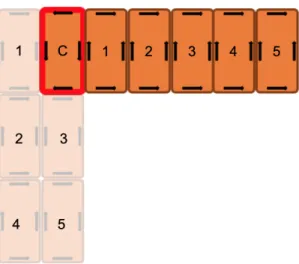
Figure 3-2: Example of shapeshifting sequence generated by the proposed algorithm. The initial configuration can be seen on the left and the goal configuration on the right. Coordinator boats are outlined in red.
3.3
Trajectory Generation
For the trajectory generation step of the shapeshifting, we use the approach developed by Gheneti et al. [12]. Because Roboats latch together to form connected vessel platforms with complex, non-convex geometries, the trajectory optimization process differs from traditional techniques. We use a three step process to generate the trajectories: first the configuration space is precomputed, second we formulate an MIQP trajectory optimization problem, and lastly the trajectory is scaled.
0°-360° 0° 180° 90° 270° 0-360° 0° 90° 180° 360° 0° 90° 1 2 3 4 Find Static Obstacle Contour
Build C-Space Partition Graph
Search for Convex Hull Path
Optimize Trajectory
Precomputation
Trajectory Optimization
Trajectory Scaling
Evaluate Discrete States Adjust Trajectory Duration
Using this approach, we are able to generate trajectories for shapeshifting in real-time for many different shapes and scenarios. This results in the calculation of T from the problem formulation. We verify the feasibility of these trajectories with experiments in a swimming pool which we will discuss further in Chapter 5.
3.4
Trajectory Tracking
Once the shapeshifting sequence is planned and the trajectories are generated, the Roboats need to track those trajectories in order to complete the shapeshift. In order to do this, we use a control scheme presented by Park et al. [21]. In their Robust Control approach, they implement a feedback control system that works for vessels connected in any configuration. Their work relies on adopting a coordinated robust control scheme which works seamlessly in our coordinator-worker framework. One of the boats is designated as the coordinator and it computes all of the necessary control inputs for the propellers of every boat in the platform. Using this approach simplifies the design of the feedback controller and the resulting closed-loop control scheme has several advantages over other state of the art approaches as described in [21]. Figure 3-4 shows a block diagram of the control scheme that allows us to perform complex shapeshifts. By using this control scheme, the associated F is generated at run time, satisfying the problem formulation.
Chapter 4
Shapeshifting Sequence Planner
One of the main contributions of this work is the development of an algorithm that provides an efficient solution to the shapeshifting problem for a set of heterogeneous Roboats with 2 coordinators and any number of workers. In this chapter, we will describe this algorithm in depth and provide a theoretical analysis on it’s correctness and time complexity.
4.1
Problem Formulation
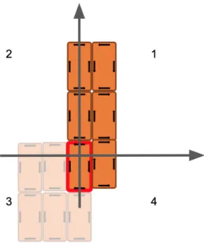
We first start with a problem formulation and describe the notation that will be used. The heterogeneous shapeshifting problem can be seen as finding a sequence of unlatching commands, L, and intermediate configurations, C, that when combined with trajectory optimization and trajectory tracking, will result in shapeshifting an initial configuration of Roboats I, into a goal configuration G. The initial and goal configurations have three constraints. First, each configuration must contain a shared coordinator with the same orientation. Second, we will consider the coordinator as the origin of a two dimensional grid. Each configuration, must be contained within a single quadrant, and the initial and goal configurations must occupy diagonal quad-rants. For example if the initial configuration is contained within quadrant 1, the goal configuration must be contained within quadrant 3. Examples of valid and invalid initial and goal configurations can be seen in Figure 4-1.
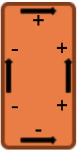
With regards to the planned sequence, each latching command ℓ consists of a list of Roboats and their respective latching points that are included in that command. Currently, each Roboat is outfitted with 6 latching points, 3 male and 3 female. The bow and stern each have one latching pointing that are male and female respectively. In addition, the starboard and port each have 2 latching points, male and female respectively. A diagram of the latching configuration can be seen in Figure 4-2.
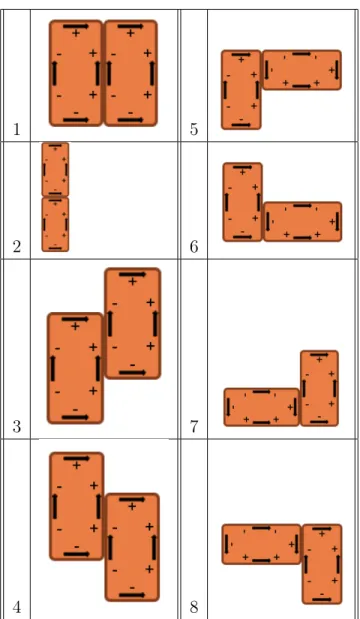
By using this latching configuration, a total of 8 different latching possibilities exist between two different Roboats. These 8 possibilities can be seen in Table 4.1.
Using these different connection types, we can represent our connected Roboat configurations (I, G) as directed graphs. We represent each Roboat in the configu-ration as a node, with the labels ’coordinator’ or ’worker’ depending on the type of Roboat. We represent each connection between two roboats as two labeled, directed edges. The edge that starts on the male latch Roboat and terminates on the female latch Roboat is labeled with a positive number that corresponds to the connection type as shown in the table. The edge that starts at female latch Roboat and termi-nates at the male latch Roboat is labeled with a negative number that corresponds to the connection type. Using this formulation, we propose a greedy, graph based algorithm for solving the shapeshifting problem in the next section.
4.2
Algorithm Overview
The algorithm we propose in this section is a greedy, graph based algorithm that utilizes breadth and depth first searches in order to solve for a shapeshifting plan. The inputs to this algorithm are the initial and goal configurations subject to the constraints that were laid out in the previous section in the formulation.
(a) This is an example of a valid initial and goal configuration as quadrants 1 and 3 are diagonal from each other.
(b) This is an example of an invalid initial and goal configuration as they do not lie in diago-nal quadrants (1 and 4).
Figure 4-1: Two examples of initial and goal configurations. The goal configuration is partially transparent.
Figure 4-2: Diagram of the latching configuration on a Roboat. The plus signs indicate a male latching component while the minus signs indicate a female latching component.
4.2.1
Greedy Shapeshift Algorithm
Once the initial and goal configurations are obtained, the algorithm starts a loop that terminates when there are no more nodes in the initial configuration. During each iteration we perform the find_overlap subroutine that finds the maximum overlap between the initial and goal configurations in a greedy fashion. Once the overlap is found, the nodes used in that overlap are removed from the initial and goal configura-tions so that they are not accounted for in the next steps of the algorithm. The nodes found in the maximum overlap are appended to the overall plan with their respective locations in the initial and goal configurations. These are the nodes that will be unlatched from the initial configuration and placed in the goal configuration at each step during the shapeshifting process. The psuedo-code for the overall shapeshifting algorithm can be found in Algorithm 1.
4.2.2
Find Overlap
The core logic for the shapeshifting algorithm is within find_overlap function. This function greedily finds the largest overlap of nodes between the initial and goal con-figurations subject to the geometric constraints imposed by the Roboat hardware.
1 5
2 6
3 7
4 8
Table 4.1: Table of the 8 possible Roboat connections.
First, a Breadth First Search (BFS), starting from the coordinator, is run on the ini-tial and goal configuration graphs to create tree structures that include the parents and children of each of the nodes. Next, we iterate through all of the leaf nodes in the initial configuration. A leaf node is defined as a node with no children as a result of the BFS and they can be safely removed from the configuration without creating a disconnect between other worker Roboats and the coordinator.
As we iterate through each of the potential leaves in the initial configuration, we also iterate through each of the root nodes in the goal configuration. A root node
Result: Plan of maximum overlaps at each step. initial_configuration; goal_configuration; plan = []; while count(initial_configuration_nodes) != 0 do find_overlap(initial_configuration, goal_configuration); plan.append(overlap);
delete used initial_configuration nodes; end
return plan
Algorithm 1: Greedy Shapeshift Algorithm.
has a direct connection to the coordinator, or nodes that have already been found in overlaps from the previous iterations of the algorithm. The idea behind this is that we will build the goal configuration from the coordinator to the leaf workers by finding leaf workers that we can safely remove from the initial configuration.
For each pair of leaf and root nodes, we perform an augmented Depth First Search (DFS) simultaneously. While performing the depth first search, we only add nodes to the exploration stacks if the edge labels between the nodes are equivalent in the initial and goal configuration graphs. This ensures that the connection types between the Roboats in each of the configurations is equivalent and that it is a valid over-lap. Once the largest possible overlap is found by exhausting this search, we ensure that the overlap abides by the geometric constraints detailed above by executing the valid_overlap subroutine. If the overlap that has been found is not valid, we re-move the most recently added node and determine if this is a valid overlap. This most recently added node removal repeats until a valid overlap is found. In the worst case, the maximum overlap will consist of only one leaf and root node as it is trivial that they overlap. The psuedo-code for the find_overlap subroutine can be seen in Algorithm 2.
4.2.3
Valid Overlap
This subroutine of the shapeshifting algorithm is used to determine whether or not a given overlap is valid with respect to geometric constraints. Due to the accuracy of
Result: Maximum overlap between initial and goal configurations. BFS(initial_configuration);
BFS(goal_configuration); largest_overlap;
current_overlap;
for leaf in initial_configuration do for root in goal_configuration do
create leaf stack; create root stack;
largest_overlap = None; while leaf stack not empty do
add leaf.pop to current_overlap; add root.pop to largest_overlap;
if leaf.pop.parent.edge.type == root.pop.parent.edge.type then add leaf.parent to leaf stack;
add root.children to root stack; end
end
while not valid_overlap(current_overlap do remove current_overlap.most_recent end
if current_overlap > largest_overlap then largest_overlap = current_overlap; end
end
return largest_overlap end
Algorithm 2: Find Overlap Algorithm.
localization systems and the required protruding hardware for the latching systems, it would be impossible for a Roboat to navigate and latch into a location that is only large enough for one Roboat. We refer to this as a narrow corridor as the authors of [26] do. Therefore, we propose an algorithm that ensure the proposed overlap does not contain any narrow corridors and will not result in any narrow corridors in future steps. Figure 4-3 shows a depiction of configurations that violate the geometric constraints.
In order to determine if the configuration is valid, we first iterate through the nodes in our graph and place them on a 2-Dimensional grid, using the connection list in Table 4.1 to populate the grid. Each node occupies 2 grid cells as the each
(a) This configuration contains a narrow cor-ridor and is invalid for an overlap.
(b) This configuration would result in a nar-row corridor in the future.
Figure 4-3: Examples of invalid overlapping configurations.
Roboat’s length is twice it’s width. Once the grid is created, we iterate through and check for narrow corridors by placing a test Roboat in every grid location. This is easy to do as we are now in a geometric representation of the configuration instead of a graph. After the iteration if no narrow corridors are found the subroutine returns true and the overlap is deemed valid.
Result: Boolean
construct grid of Roboats; for cell in grid do
check narrow corridor; end
if narrow corridor exists then return False;
else
return True; end
4.2.4
Result
Once the algorithm is executed, the resulting plan containing the maximum overlap at each step is returned. Using this, it is easy to construct a sequence of unlatching and latching commands to ferry the worker Roboats to the correct locations to create the goal configuration.
4.3
Algorithm Analysis
In this section we will analyze the correctness and time complexity of the proposed algorithm.
4.3.1
Correctness
We first analyze the correctness. We define correctness as a guarantee that the al-gorithm will return a plan for all inputs that satisfy the constraints described the problem formulation. In order to show that this algorithm will always return a valid plan, we will inspect the find_overlap subroutine. Although this algorithm greedily searches for the maximum overlap, in the worst case, it is always possible to have an overlap of one leaf node from the initial configuration with a root node from the goal configuration. This is a trivial overlap that gives the algorithm a plan to fall back on in the worst case when overlaps that are larger than one boat are either invalid due to geometric constraints or non-existent because the initial and goal configurations are extremely different and contain no overlapping sub-configurations.
4.3.2
Time Complexity
With regards to the time complexity, we first denote the total number of worker boats in each configuration as 𝑛. We can see that in the worst case, when the maximum overlap is only one node at each step, the outer most loop will run 𝑂(𝑛) times. When examining the find_overlap subroutine. We first examine that we run two BFSs which have a time complexity of 𝑂(𝑛). Next when finding the largest overlap, we
consider the worst case where an overlap of size 𝑛, 𝑛 − 1, 𝑛 − 2, ... exists but they all violate the geometric constraint except for the size 1 overlap. This results in performing 𝑛 overlap checks. Lastly we examine the valid_overlap subroutine and it’s complexity. In the worst case, the grid we construct is 𝑛 × 𝑛 and is iterated over in it’s entirety resulting in a time complexity of 𝑂(𝑛2). When combining the time complexity from all of these parts, we find that our algorithm is 𝑂(𝑛4). However,
this analysis is for the absolute worst case which is extremely infeasible and will very likely never be encountered in a real life shapeshifting scenario as the initial and goal configurations required for the worst case performance do not relate to the proposed use cases of shapeshifting.
4.4
Example
In this section we will walk through an example of the algorithm step by step. The initial and goal configurations can be seen in Figure 4-4. First, we look for the largest overlap between leaves from the initial configuration and roots from the goal configuration. The largest overlap that is found is [[𝑖4 : 𝑔2]; [𝑖5, 𝑔3]]. We then check
to see that it is a valid overlap and does not violate any of the geometric constraints. As there are no narrow corridors in this overlap we move onto the next step which can be seen in Figure 4-5.
Now we search for the largest overlap using the remaining nodes in the initial and goal configurations. Similar to the previous step, we now see that the maximum overlap is [[𝑖2 : 𝑔4]; [𝑖3, 𝑔5]]. Again there are no geometric violations so this is a valid
overlap. Figure 4-6 shows the resulting configurations once this step is completed.
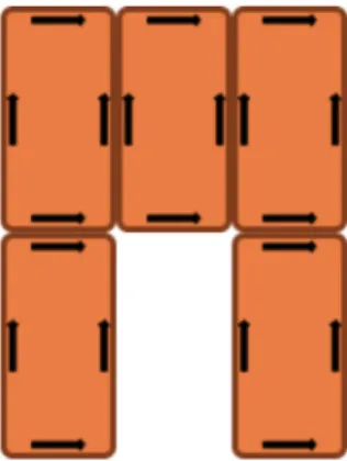
Now we are on the last step, and it is easy to see that the final overlap is the trivial one boat overlap of [[𝑖1 : 𝑔1]]. The final configuration is shown in Figure 4-7.
Figure 4-4: Initial and goal configuration for the working example. The goal config-uration is partially transparent.
Figure 4-5: Intermediate step 2 in our working example. As goal nodes 2 and 3 have already been used in an overlap they are denoted with a different color.
4.5
Software Implementation
For the software implementation of the shapeshifting sequence planning algorithm, we used Python along with the third party library graph-tool [1]. The full implementation along with Jupyter Notebooks with examples can be found at
https://github.com/rkelly07/shapeshift.
Figure 4-6: Intermediate step 3 in our working example. As goal nodes 4 and 5 have already been used in an overlap they are denoted with a different color.
Figure 4-7: The final step in our working example where all of the overlaps have been found and the goal configuration has been reached.
multiple test cases that include scenarios where the geometric constraints would be violated with the maximum overlap.
The first scenario we will discuss is the transformation from a platform to a bridge. This scenario relates to our motivating use case of dynamic infrastructure and can be
seen in Figure 4-8.
Figure 4-8: Shapeshifting from platform to bridge for Python implementation test.
When running the algorithm on this test case it results in a two step overlap plan. In the first step, we find the largest overlap between the initial and goal configurations is: [𝑖4 : 𝑔4]; [𝑖5 : 𝑔5]; [𝑖2 : 𝑔1]; [𝑖3 : 𝑔2]. In the second step we find the trivial mapping of
[𝑖1 : 𝑔3]. The algorithm is also able to calculate the plan for the reverse scenario.
Another scenario can be seen in Figure 4-9. Without accounting for the geometric constraints, the planner would return: [𝑖4 : 𝑔4]; [𝑖5 : 𝑔5]; [𝑖6 : 𝑔6]; [𝑖2 : 𝑔1]; [𝑖3 : 𝑔3] in
the first step. However, that would results in a narrow corridor too small for the remaining Roboat to complete the shapeshift. Therefore, the plan that is found by the algorithm is: [𝑖3 : 𝑔3]; [𝑖6 : 𝑔6]; [𝑖5 : 𝑔5]; [𝑖4 : 𝑔4] for the first step and [𝑖1 : 𝑔1]; [𝑖2 : 𝑔2]
Chapter 5
Evaluation
In order to evaluate our proposed method for shapeshifting, we have developed a set of hardware prototype Roboats. Using these hardware prototypes, we are able to perform multi-step shapeshifts in a swimming pool. This chapter will highlight the software and hardware that we have developed in order to execute these shapeshifts, along with a number of experiments and an analysis of their performance.
5.1
Hardware Platform
The hardware platform that we used in order to perform our pool tests consisted of Roboat 1:4 scale prototypes. Each Roboat was outfitted with four thrusters config-ured to allow for holonomic motion as shown in Figure 5-1.
Each Roboat is also equipped with a microcontroller that allows for control of these thrusters. For localization, the coordinator Roboat is equipped with two beacons for "Indoor GPS". These two beacons communicate with four stationary beacons that are stationed around the pool and are able to localize with an accuracy of ±2 cm. Figure 5-2 shows the beacons on the coordinator Roboat and one of the stationary beacons.
Another important aspect of the hardware platform is the latching mechanism. Each Roboat is outfitted with three male and three female latches as described in chapter 4. In order to latch the Roboats together, we have implemented a system that
Figure 5-1: Thruster configuration for 1:4 scale Roboat.
uses electromagnets at each of the latching locations. The female side is the powered electromagnet while the male side is a metal block. We have also included a set of plastic guides in order to increase the tolerance needed to perform a latch. Figure 5-3 shows the hardware implementation of the electromagnetic latching system.
In addition to the electromagnets, each latching point contains RFID technology, allowing the boats to communicate and determine their own configuration. The male sides contain RFID readers that are connected to a micro-controller while the female points contain RFID tags with unique IDs. Each Roboat is able to read in the IDs of the tags that are next to their RFID readers when latched and relay this information to the coordinator to build a graph that describes the connected configuration. Figure 5-4 shows the RFID tag information for the three Roboats we used in our experiments.
5.2
Shapeshifting Execution
In order to execute shapeshifts on a hardware platform, we developed an implemen-tation of a state machine in ROS [3], using the SMACH [4] software package. A block diagram of the state machine can be seen in Figure 5-5.
(a) Coordinator boat with beacons. (b) Stationary beacon.
Figure 5-2: Indoor GPS beacon system for localization.
Navigate. The entry state is Configuration Verifier, which either exits the state machine if the goal condition is met or transitions to Unlatch. Unlatch will transition to Navigate and Navigate transitions back to Configuration Verifier. We will now describe each of these states in detail.
5.2.1
Configuration Verifier
The Configuration Verifier state is the entry point and exit point of the state machine. It’s purpose is to read in the current configuration of the Roboats and compare it to the goal configuration. This is achieved by making a ROS Service Call to a node that keeps track of the current latches using the RFID information. The format of the configurations is a list of edges in the Roboat configuration graph. This uniquely describes every Roboat configuration. An edge contains an origin boat id, destination boat id, origin boat latch point, and destination boat latch point. By iterating through all of the current latches in the hardware configuration and comparing them with the goal configuration we are able to determine if it has been achieved. By representing the goal configuration as a set of edges, we are able to perform constant time lookup for each edge which results in the Configuration Verifier state running linear in time
Figure 5-3: Electromagnet and RFID Latching system.
with respect to the total number of edges in the current hardware configuration.
5.2.2
Unlatch
The Unlatch state is the simplest of the states and is responsible for sending the unlatch commands to the boats. This is achieved by publishing the latch command for the current shapeshift step to a ROS publisher that allows the Coordinator to relay the proper commands to each worker boat. The format of this message is the Roboat id, followed by three Boolean variables that correspond to female latches d, e, and f respectively.
5.2.3
Navigate
The Navigate state is responsible for publishing the current trajectory that was found during the trajectory optimization step so that the controller is able to perform tra-jectory tracking. First the generated tratra-jectory is read in and transformed into the current reference frame. Next, each step in the trajectory is published at a rate of 5Hz. Finally, once the entire trajectory has been published, the configuration verifier
Figure 5-4: RFID Tag configuration for the prototype Roboats used in our experi-ments.
algorithm is repeatedly called. However, instead of verifying that the goal configura-tion has been reached, the algorithm confirms that the current configuraconfigura-tion matches the next step from the generated sequence plan. Only once the current configuration is equal to the next step will the trajectory tracking terminate and move to the next state in the state machine.
5.2.4
Contribution
This state machine implementation is critical to the shapeshifting application. With-out a integrated execution method, each of the shapeshifting steps, sequence planning, trajectory generation, and trajectory tracking, would be disconnected and unable to achieve shapeshifts. This state machine is extremely flexible and able to perform any
Figure 5-5: Shapeshift State Machine Block Diagram.
shapeshift defined by the original problem formulation. It is also robust as shown by our experimental results in the next section.
5.3
Experimental Results
In order to verify the robustness of the proposed integrated shapeshifting execution state machine, we performed numerous experiments in a swimming pool. Our exper-iments tested three different scenarios, each consisting of four different shapeshifting steps. The Roboats all started and ended connected to each other through latching possibility 1 as shown in Figure 5-2a.
Each scenario also tested different capabilities of the shapeshifting system. Sce-nario 1 was the simplest and demonstrates the Roboats shapeshifting from a horizon-tal platform to a vertical bridge and back, as seen in Figure 5-6.
Scenario 2 was more complex and demonstrates the Roboats ability to rotate in tight quarters and includes 90 and 270 degree rotations. The steps of this scenario can be seen in Figure 5-7.
Figure 5-6: Shapeshift experiment 1 sequence.
Scenario 3 demonstrates how a multi-vessel platform can latch onto multiple points even in tight quarters. The intermediate steps can be seen in Figure 5-8.
Pictures of the execution of these scenarios in the swimming pool can be seen in Table 5.1.
We performed each of these scenarios four times and recieved 75%, 75%, and 100% completion respectively. For scenario 1, the error case happened in the third trial. this was due to the coordinator losing proper localization and being unable to complete one of the steps. A table with detailed run times for each experiment can be seen in Table 5.2.
For scenario 2, we believe that the failure cause for the first trial is due to the complexity of the 270 degree rotation need to reach step 4 from step 3. However, we believe this success rate could be improved by making the trajectory longer in order to allow for more error recovery in the trajectory tracking. The times for each of the steps can be seen in Table 5.3.
For scenario 3, all 4 trials were successful. The respective times can be found in Table 5.4.
Videos of the three different scenarios can be found at this Dropbox link:
Figure 5-7: Shapeshift experiment 2 sequence.
Scenario 1 Scenario 2 Scenario 3 Step 1 Step 2 Step 3 Step 4 Step 5
Table 5.1: Table of different configurations of the Roboats in the three testing sce-narios.
Trial Number Step 1→2 Step 2→3 Step 3→4 Step 4→5 Total Trial 1 69s 65s 60s 55s 249s Trial 2 70s 66s 66s 56s 258s Trial 3 N/A N/A N/A N/A N/A Trial 4 70s 66s 62s 54s 252s Average 69.7s 65.7s 62.7s 55s 253s
Trial Number Step 1→2 Step 2→3 Step 3→4 Step 4→5 Total Trial 1 N/A N/A N/A N/A N/A Trial 2 90s 66s 66s 45s 267s Trial 3 90s 70s 91s 46s 297s Trial 4 84s 62s 74s 50s 270s Average 88s 66s 77s 47s 278s
Table 5.3: Times for each step in the four trials for Scenario 2.
Trial Number Step 1→2 Step 2→3 Step 3→4 Step 4→5 Total Trial 1 65s 80s 93s 33s 271s Trial 2 47s 83s 86s 27s 243s Trial 3 53s 87s 91s 30s 261s Trial 4 44s 82s 91s 28s 245s Average 52.25s 83s 90.25s 29.5s 255s
Chapter 6
Conclusion
In this thesis, we proposed new algorithms for shapeshifting fleets of heterogeneous Roboats. Using the Roboat project as a motivating use case, we described why using a coordinator-worker framework is beneficial and why the development of new algorithms was needed.
In chapter 3 we described the shapeshifting problem as a whole. We examined the three distinct phases of shapeshifting which were Sequence Planning, Trajectory Generation, and Trajectory Tracking. Each of these aspects are integral to perform-ing a shapeshift and describe the approaches developed by Gheneti et al. [12] for Trajectory Generation and Park et al. [21] for Trajectory Tracking. This chapter also highlights the need for the development of a new multi robot reconfiguration algorithm.
In the fourth chapter, we describe one of the main contributions of this thesis: the shapeshifting Sequence Planner. This is a novel algorithm that uses a greedy and graph based approach to generate a sequence of latching and unlatching commands in order to perform a shapeshift. We also provide a theoretical analysis of the algorithm and provide multiple test cases to show the results of an implementation in Python. In chapter 5, we demonstrate that it is possible to perform shapeshifts on a hard-ware platform in the swimming pool. We describe our hardhard-ware platform in depth which contains prototype 1:4 scale Roboats, electromagnets, and RFID sensors. We also describe another main contribution which is the state machine we developed in
order to execute these shapeshifts autonomously, a crucial piece of software that is the bridge between the Sequence Planning, Trajectory Generation, and Trajectory Tracking algorithms. Lastly, we describe the experiments we ran and showcase their success.
Therefore, this thesis can be used as a road map for how to perform multi-Roboat shapeshifts and provides analysis on the new algorithms developed as well as proof that the system we developed is feasible and works on a hardware platform. We believe this work will be very beneficial to those attempting to self-reconfigure heterogeneous robots in the future, as well as provide guidance for the Roboat team as they move on from the 1:4 scale platform and make the vision of shapeshifting Roboats for urban use cases in Amsterdam a reality.
6.1
Future Work
Although this thesis provides a novel solution to the multi-Roboat shapeshifting prob-lem, there is room for further research in multiple settings. First, the proposed algo-rithm only considers two coordinator Roboats. This could be extended to allow for quicker shapeshifting by ferrying multiple sets of connected worker Roboats in paral-lel. Additionally, there is currently the constraint that there is a shared coordinator in the center of the initial and goal configuration. By relaxing this constraint and allowing the shared coordinator to be anywhere in the configuration, many different types of shapeshifts could be accounted for. Additionally, further research could be done in more efficient geometric constraint checking. This was the bottleneck of the algorithm with regards to run time. Although we learned that in practice this algo-rithm still performs well, developing a more tightly bound valid_overlap subroutine would be an obvious next step in research.
Another area of future work would be increasing the current scale of the shapeshift-ing on two fronts. First, as the Roboat project moves further along, it will be crucial to test these algorithms on the 1:2 scale and full scale Roboats. Although the algo-rithms presented are size independent, when implementing on the hardware there will
be a need to tune parameters to ensure that the shapeshifts are able to be executed. Also, although the current electromagnetic latching system is sufficient for the 1:4 scale boats, we believe it is a solution that is only viable for these prototypes and not the larger Roboats. Through conducting our experiments, we learned that having a reliable localization system, along with a more robust latching solution would lead to a more robust shapeshifting system. Additionally, performing shapeshifts with more than 3 Roboats to further demonstrate the robustness of our state machine is an obvious next step to prove that multi-Roboat shapeshifting is feasible for the real world use cases of making dynamic platforms and bridges in the canals of Amsterdam. As more Roboats are developed, it will be possible to further test this software and validate our results.
Appendix A
Software Packages
This section includes a list of the different software packages and dependencies used. There may be some subdependencies missing from this list.
1. graph_tool Python library with functions for computing with graphs
2. ipython Notebook interface for programming in Python
3. numpy Matrix processing in Python
4. pickle Object serialization in Python
5. ROS Robot Operating System
Bibliography
[1] graph_tool. https://graph-tool.skewed.de/. Accessed: 2019-5-13. [2] Roboat. roboat.org. Accessed: 2019-4-30.
[3] ROS. https://www.ros.org/. Accessed: 2019-5-13.
[4] SMACH,. http://wiki.ros.org/smach. Accessed: 2019-5-13. [5] Urban waterways in global cities, June 2017. Forum Report.
[6] Frederico Augugliaro, Sergei Lupashin, Michael Hamer, Cason Male, and Raf-faello D’Andrea. The flight assembled architecture installation: Cooperative contruction with flying machines. IEEE Control Syst., 34(4):46–64, August 2014. [7] José Baca, S. G M Hossain, Prithviraj Dasgupta, Carl A Nelson, and Ayan Dutta. Modred: Hardware design and reconfiguration planning for a high dex-terity modular self-reconfigurable robot for extra-terrestrial exploration. Robotics and Autonomous Systems, 62(7):1002–1015, 2014.
[8] Daniel C. Fernandez and Geoffrey A. Hollinger. Model predictive control for underwater robots in ocean waves. IEEE Robotics and Automation Letters, 2:1– 1, 01 2016.
[9] Jonathan Daudelin, Gangyuan Jing, Tarik Tosun, Mark Yim, Hadas Kress-Gazit, and Mark Campbell. An integrated system for perception-driven autonomy with modular robots. Science Robotics, 3(23):eaat4983, October 2018.
[10] Lidia Furno, Mogens Blanke, Roberto Galeazzi, and David Johan Christensen. Self-reconfiguration of modular underwater robots using an energy heuristic. pages 6277–6284, 09 2017.
[11] Banti Gheneti. Reconfigurable autonomous surface vehicles: Perception and trajectory optimization algorithms. Master’s thesis, Massachusetts Institute of Technology, 2019.
[12] Banti Gheneti, Shinkyu Park, Ryan Kelly, Drew Meyers, Pietro Leoni, Carlo Ratti, and Daniela Rus. Trajectory planning for shapeshifting of au-tonomous vessels. preprint, 2019. https://web.mit.edu/bgheneti/www/IEEE-MRS-Shapeshifting-long.pdf.
[13] Gene Grimm, Michael J. Messina, Sezai E. Tuna, and Andrew R. Teel. Examples when model predictive control is non-robust. Automatica, 40:1729–1738, 10 2004. [14] Bruno Joao Nogueira Guerreiro, Carlos Silvestre, Rita Cunha, and António Manuel Santos Pascoal. Trajectory tracking nonlinear model predictive con-trol for autonomous surface craft. 2013 European Concon-trol Conference (ECC), pages 3006–3011, 2009.
[15] Shahab Heshmati-alamdari, Alina Eq, George Karras, Dimos V Dimarogonas, and Kostas Kyriakopoulos. A self-triggered visual servoing model predictive control scheme for under-actuated underwater robotic vehicles. 05 2014.
[16] Zhixiang Liu, Youmin Zhang, Xiang Yu, and Chi Yuan. Unmanned surface ve-hicles: An overview of developments and challenges. Annual Reviews in Control, 41, 05 2016.
[17] Justin Manley. Unmanned surface vehicles, 15 years of development. pages 1 – 4, 10 2008.
[18] Luis Mateos, Wei Wang, Banti Gheneti, FÃąbio Duarte, Carlo Ratti, and Daniela Rus. Autonomous latching system for robotic boats. to appear in IEEE Inter-national Conference on Robotics and Automation (ICRA), 2019.
[19] Wasif Naeem, Rhondasutton Sutton, and Tao Xu. An integrated multi-sensor data fusion algorithm and autopilot implementation in an uninhabited surface craft. Ocean Engineering, 39:43–52, 01 2012.
[20] I O’Hara, J Paulos, J Davey, N Eckenstein, N Doshi, T Tosun, J Greco, J Seo, M Turpin, V Kumar, and M Yim. Self-assembly of a swarm of autonomous boats into floating structures. In 2014 IEEE International Conference on Robotics and Automation (ICRA), pages 1234–1240, May 2014.
[21] Shinkyu Park, Erkan Kayacan, Carlo Ratti, , and Daniela Rus. Coordinated control of a reconfigurable multi-vessel platform: Robust control approach. to appear in IEEE International Conference on Robotics and Automation (ICRA), 2019.
[22] James Paulos, Nick Eckenstein, Tarik Tosun, Jungwon Seo, Jay Davey, Jonathan Greco, Vijay Kumar, and Mark Yim. Automated self-assembly of large maritime structures by a team of robotic boats. IEEE Transactions on Automation Science and Engineering, 12:1–11, 07 2015.
[23] J W Romanishin, K Gilpin, and D Rus. M-blocks: Momentum-driven, magnetic modular robots. In 2013 IEEE/RSJ International Conference on Intelligent Robots and Systems, pages 4288–4295, November 2013.
[24] Michael Rubenstein, Alejandro Cornejo, and Radhika Nagpal. Robotics. pro-grammable self-assembly in a thousand-robot swarm. Science, 345(6198):795– 799, August 2014.
[25] Daniela Rus and Marsette Vona. Crystalline robots: Self-reconfiguration with compressible unit modules. Autonomous Robots, 2001.
[26] J. Seo, M. Yim, and V. Kumar. Assembly sequence planning for constructing planar structures with rectangular modules. In 2016 IEEE International Con-ference on Robotics and Automation (ICRA), pages 5477–5482, May 2016. [27] Jungwon Seo, Jamie Paik, and Mark Yim. Modular reconfigurable robotics.
Annual Review of Control, Robotics, and Autonomous Systems, 2(1):null, 2019. [28] Jongho Shin, Dong Jun Kwak, and Young-il Lee. Adaptive path-following control
for an unmanned surface vessel using an identified dynamic model. IEEE/ASME Transactions on Mechatronics, PP:1–1, 01 2017.
[29] Wei Wang, Luis Mateos, Shinkyu Park, Pietro Leoni, Banti Gheneti, FÃąbio Duarte, Carlo Ratti, and Daniela Rus. Design, modeling, and nonlinear model predictive tracking control of a novel autonomous surface vehicle. In IEEE In-ternational Conference on Robotics and Automation (ICRA), pages 1–8, 2018. [30] J Werfel, Yaneer Bar-Yam, D Rus, and R Nagpal. Distributed construction
by mobile robots with enhanced building blocks. In 2006 IEEE International Conference on Robotics and Automation (ICRA), pages 2787–2794, 2006. [31] M Yim, W Shen, B Salemi, D Rus, M Moll, H Lipson, E Klavins, and G S
Chirikjian. Modular Self-Reconfigurable robot systems [grand challenges of robotics]. IEEE Robotics and Automation Magazine, 14(1):43–52, March 2007.


![Figure 3-3: Three step process to generate trajectories for shapeshifting from [12].](https://thumb-eu.123doks.com/thumbv2/123doknet/13925149.450117/26.918.133.784.612.1042/figure-step-process-generate-trajectories-shapeshifting.webp)
![Figure 3-4: Diagram of Coordinated Robust Control Scheme from [21].](https://thumb-eu.123doks.com/thumbv2/123doknet/13925149.450117/28.918.210.709.425.745/figure-diagram-coordinated-robust-control-scheme.webp)