Publisher’s version / Version de l'éditeur:
Cement & Concrete Composites, 28, September, pp. 685-695, 2006-09-01
READ THESE TERMS AND CONDITIONS CAREFULLY BEFORE USING THIS WEBSITE.
https://nrc-publications.canada.ca/eng/copyright
Vous avez des questions? Nous pouvons vous aider. Pour communiquer directement avec un auteur, consultez la
première page de la revue dans laquelle son article a été publié afin de trouver ses coordonnées. Si vous n’arrivez pas à les repérer, communiquez avec nous à [email protected].
Questions? Contact the NRC Publications Archive team at
[email protected]. If you wish to email the authors directly, please see the first page of the publication for their contact information.
NRC Publications Archive
Archives des publications du CNRC
This publication could be one of several versions: author’s original, accepted manuscript or the publisher’s version. / La version de cette publication peut être l’une des suivantes : la version prépublication de l’auteur, la version acceptée du manuscrit ou la version de l’éditeur.
For the publisher’s version, please access the DOI link below./ Pour consulter la version de l’éditeur, utilisez le lien DOI ci-dessous.
https://doi.org/10.1016/j.cemconcomp.2006.05.010
Access and use of this website and the material on it are subject to the Terms and Conditions set forth at
Theoretical and experimental study of microcell and macrocell corrosion in patch repair
Qian, S. Y.; Zhang, J. Y.
https://publications-cnrc.canada.ca/fra/droits
L’accès à ce site Web et l’utilisation de son contenu sont assujettis aux conditions présentées dans le site LISEZ CES CONDITIONS ATTENTIVEMENT AVANT D’UTILISER CE SITE WEB.
NRC Publications Record / Notice d'Archives des publications de CNRC:
https://nrc-publications.canada.ca/eng/view/object/?id=93895508-c15d-4c8d-832b-01c8719d4ea4 https://publications-cnrc.canada.ca/fra/voir/objet/?id=93895508-c15d-4c8d-832b-01c8719d4ea4
http://irc.nrc-cnrc.gc.ca
Theoretical and experimental study of microcell and macrocell
corrosion in patch repairs of concrete structures
N R C C - 4 8 6 5 9
Q i a n , S . ; Z h a n g , J . ; Q u , D .
A v e r s i o n o f t h i s d o c u m e n t i s p u b l i s h e d i n / U n e v e r s i o n d e c e d o c u m e n t s e t r o u v e d a n s : C e m e n t & C o n c r e t e C o m p o s i t e s , v . 2 8 , n o . 8 , S e p t . 2 0 0 6 , p p . 6 8 5 - 6 9 5 d o i :1 0 . 1 0 1 6 / j . c e m c o n c o m p . 2 0 0 6 . 0 5 . 0 1 0
Theoretical and experimental study of microcell and macrocell
corrosion in patch repairs of concrete structures
Shiyuan Qian*, Jieying Zhang, Deyu Qu Institute for Research in Construction
National Research Council Canada, Ottawa, Ont., Canada K1A 0R6
Abstract
Patch repair is commonly used to rectify localized corrosion induced damage in concrete structures. However, inadequate durability in patch repair systems caused by new corrosion attack is prevalent. From the prevailing understanding, the mechanism is attributed to macrocell corrosion formed between repaired area (called patch) and its adjacent unrepaired area (called substrate), and thereby ensuring electrochemical compatibility between the two areas is deemed to be the key element to reduce the corrosion risk and thus to achieve a successful repair. This paper examined the corrosion mechanism and the concept of compatibility in patch repair systems from fundamental electrochemical principles and experimental verification. It was illustrated that both macrocell and microcell corrosion mechanisms could play significant roles, and the total corrosion could be underestimated if the latter is overlooked. Although the incompatibility serves as the driving force for the macrocell corrosion, in light of corrosion kinetics, it was shown that the corrosion magnitude depends more on the individual corrosion kinetics of the anode or cathode.
Keywords: Patch repair; Corrosion; Macrocell; Microcell; Corrosion kinetics
* Corresponding author. Tel.:1-613-993-3814; Fax: 1-613-952-8102 E-mail address: [email protected] (S. Qian)
1. Introduction
Corrosion of the reinforcing steel is a major deterioration problem of concrete structures. Corrosion prevention and repair of concrete structures will continue to be an important strategy for the rehabilitation of corrosion-damaged structures. Patch repair is a commonly used method in concrete structures, especially on highway bridge decks, for rectifying localized damage in concrete induced by corrosion of the reinforcing steel. The repair process entails removal of loose concrete that has cracked, spalled, or delaminated, often by surface treatment of the steel reinforcement and the old concrete, then replacing the defective concrete with patching materials. From an electrochemical viewpoint, a patch repair is designed to remove the anodic reaction on the reinforcing steel that existed before the repair and to prevent it from recurring by making it a passive area. The change of corrosion state in the repaired area, however, brings about new corrosion risk in the surrounding areas because they are often in electrical contact. Many patch repairs and their surrounding areas have exhibited new corrosion damage after a few months to a year.
In patch repair systems, the repaired area (called patch) and the adjacent unrepaired areas (called substrate) provide the embedded steel bars with dissimilar electrochemical environments. The protective high pH of sound concrete, such as in a newly repaired area, normally passivates the embedded reinforcing steel. If the concrete is contaminated by chlorides and/or becomes carbonated, such as in the substrate, active corrosion can initiate in the reinforcing steel. When the active steel and passive steel are put into electrical contact, macrocell corrosion can form between them, in which the former is polarized anodically and the latter polarized cathodixally. In patch repair systems, active corrosion damage often occurs in the substrate or at the interface, known as incipient corrosion or ring-anode effect, because concrete in the substrate is normally more corrosive than in the patch. It was found that the patch repair induces or enhances the active corrosion in the substrate if its chloride content is above a threshold level and sufficient moisture is present [1,2] as supported by many experimental detections of the macrocell corrosion formed between them [1,2,3,4,5]. This has led to the prevailing understanding that the main corrosion mechanism in patch repair is the macrocell corrosion.
The total dissolution of the steel in the active area however, is determined by both the macrocell and microcell corrosion currents that might coexist. The role of microcell corrosion has not been fully addressed in patch repair systems. The microcell corrosion could also be induced in the substrate by the patch repair. For example, the damaged area, before the repair, was more corrosive to the steel than its surrounding substrate and served as an anodic site, with the steel in the adjacent substrate thus being cathodically protected. The repair would therefore remove the corrosive environment and consequently, the cathodic protection on the steel in the substrate. As a result, the microcell corrosion could occur spontaneously in the substrate, especially if its chloride content is higher than the threshold level [5,6]. Some limited data have enabled a comparison of the magnitude of microcell and macrocell corrosion activities. Li and Yuan [2] showed that steel bars in the substrate near the repair interface would lead to corrosion exacerbation and the influenced area increased with the increase of the repaired region. Their results conformed to the theoretical illustration that a newly induced macrocell might not necessarily surpass the existing microcell corrosion if a cathodic area is not much larger than the anodic area [7]. Note that the technique to measure macrocell corrosion cannot measure microcell corrosion, and as a result, the contribution of the latter is easily overlooked and the real degree of total corrosion could be seriously underestimated. Thus, it is essential to identify the underlying mechanism and distinguish the degree of participation of both types of corrosion as to whether the induced corrosion in the patch repair system is mainly due to macrocell or microcell corrosion or both.
Another prevailing understanding is that the compatibility of patching materials with substrate is the most critical factor for a successful patch repair [8,9,10], because the incompatible properties between the patch and substrate leads to an electrochemical potential difference that serves as the driving force for the formation of macrocell corrosion [11]. The incompatibility can arise from physical properties (e.g. porosity), chemical compositions and electrochemical properties. Therefore a significant incompatibility between patch and substrate will result in a larger driving force for the macrocell corrosion to occur. A larger driving force, however, does not necessarily mean a higher rate of corrosion, because the behavior of the individual active area or passive area in terms of their reaction rates often outweighs the thermodynamic driving force in determining the rate of corrosion [12]. Some experiments also showed that a seemingly
“incompatible” repair, in which stainless steel was used to replace the carbon steel in the damaged area, brought about low macrocell corrosion with the carbon steel in the substrate [13,14,15]. This implies that the key factors affecting the characteristics of macrocell corrosion itself are not well understood and the concept of compatibility needs further examination with regards to corrosion kinetics, in addition to the thermodynamic driving force.
This paper presents a theoretical examination of the prevailing understanding of the corrosion mechanisms and their causes in patch repair systems, as well as an experimental demonstration to validate the suggested mechanisms. This study will attempt to clarify fundamental mechanism of the corrosion in concrete patch repair and enhance the current understanding of the importance of the microcell corrosion and its relation to the macrocell corrosion.
2. Theoretical consideration 2.1. Microcell corrosion
The corrosion of steel in concrete is an electrochemical process involving the transfer of electrons from one chemical species to another. Microcell corrosion refers to a corrosion process in which the mechanism is within a microscopic scale. The reactions involving consumption of metal and release of electrons are anodic reactions:
− + +
→Fe e
Fe 2 2
(1) The Fe2+ ions react with OH− to form ferrous hydroxide [Fe(OH)2]:
2 2 ) ( 2OH Fe OH Fe + + −→ (2) The Fe(OH)2 commonly reacts further with oxygen to form various oxide species such as hydrated ferric oxide (Fe2O3⋅H2O) and hydrated magnetite (Fe3O4⋅H2O), depending on pH and availability of oxygen: O H O H O Fe O OH Fe( )2 2 2 2 3 2 2 2 4 + → ⋅ + (3) O H O H O Fe O OH Fe( )2 2 2 3 4 2 4 2 6 + → ⋅ + (4)
As a contrary, reactions involving consumption of electrons and dissolved chemical species are referred to as cathodic reactions, which most likely incorporate the following steps depending on the availability of oxygen, pH of the solution, and electrochemical potential:
− − → + +O e OH O H 4 4 2 2 2 (5) 2 2 2 2 2H O+ e− → OH− +H (6) In concrete, oxygen is usually able to penetrate through the pores and micro-cracks into the steel surface and the overpotential for oxygen reduction reaction (equation 5) is low, thereby making this reaction the prevailing cathodic reaction. As the corrosion process becomes stable, the anodic oxidation and the cathodic reduction reactions will reach equilibrium, and no net current can be measured externally under this condition.
For normal concrete, the pH of the pore solution varies between 12 and 13.5, and a passive film is formed on the reinforcing steel embedded in this high alkaline environment that protects it from corrosion. For a passive steel, the open circuit potential is high (more positive) but the corrosion rate is very low (e.g. less than 0.1 μA/cm2
), and the overall reactions can be represented by the anodic (A) and cathodic (C) polarization curves in Figure 1.
Active corrosion can develop on reinforcing steel when the concrete alkalinity is reduced to a certain level (usually pH<9) due to carbonation or when the concentration of chlorides around the steel in the concrete exceeds a critical level. Under these conditions the passive film breaks down and corrosion initiates. Active corrosion is characterized by a low open circuit potential and a high corrosion rate, which is normally greater than 0.5 μA/cm2
[16]. The corrosion of active steel in a concrete pore solution with sufficient supply of oxygen can be expressed by the polarization curves A and C in Figure 2. The availability of oxygen in the concrete pore solution at the steel surface is often limited, however, the cathodic reaction rate is thereby restricted to a limiting current as shown by the bent curve B. As a result, the overall corrosion rate of active steel in concrete is commonly controlled by the rate of oxygen diffused to the metal surface.
Compare a passive steel to an active steel; the corrosion potential of the latter is more negative and corrosion rate (i.e. the anodic dissolution current) is much higher. For both types of corrosion processes, all the electrons released in the anodic reaction are consumed in the cathodic reaction by the principle of charge conservation, denoted by the following equation:
c a i
i = (7)
where ia is the anodic current and ic the cathodic current. Both anodic and cathodic reactions can
occur in micro areas (even on an atomic scale). Therefore no net current can be measured externally. Moreover, the metal normally takes up a more or less uniform electrode potential, often called the corrosion potential (Ecorr). The corresponding rate of metal dissolution at this
potential is referred to as the corrosion rate (icorr) and has the following relation:
c a corr i i
i = = (8)
2.2. Macrocell corrosion
Corrosion of reinforcing steel in concrete structures is often not uniform. Some areas are more corroded than others due to non-homogeneity and cracks in concrete or to localized chloride attack. This can also occur following a patch repair of a reinforced concrete structure, e.g., when there is a significant difference in chloride concentration between the new patch (chloride free) and its surrounding substrate (chloride contaminated). In such a commonly-occurring case, the steel becomes passivated in the patch and its electrochemical potential shifts to more positive values than that of the steel in the substrate. Especially when active corrosion is initiated in the steel embedded in the substrate, its electrochemical potential shifts significantly towards more negative values and the difference between their electrochemical potentials will be even greater. As a result, galvanic corrosion can occur between the two visibly separated areas if their reinforcing steel bars are electrically connected. This galvanic corrosion is also known as macrocell corrosion.
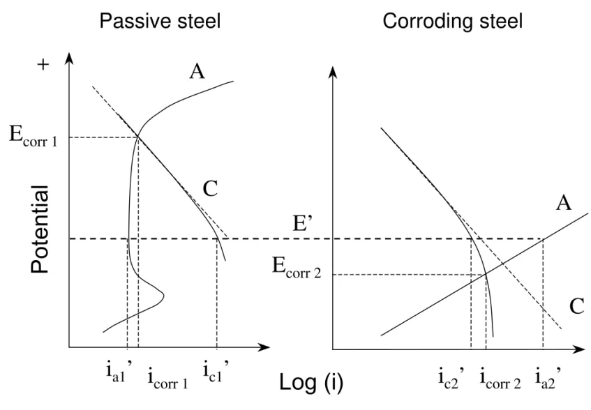
2.2.1. Macrocell corrosion between passive and active reinforcing steels
A simple two-electrode macrocell corrosion system consists of one passive steel (electrode 1) and one active steel (electrode 2) as illustrated in Figure 3. When these two electrodes are in
electrical contact in an electrolyte or concrete, the potentials of the two steels will shift to a common potential and reach a new equilibrium, assuming the resistance of the electrolyte is negligible. The active steel, which has a more negative potential (Ecorr2), will be anodically polarized to a more positive potential E’, while the passive steel, having a more positive potential (Ecorr1), will be cathodically polarized to a more negative potential E’, as shown in Figure 3. Accordingly, the anodic dissolution current in the active steel is increased from icorr2 (the corrosion current before coupling) to ia2’and the cathodic current decreased from icorr2 to ic2’. In the passive steel however, the anodic current is reduced from icorr1 to ia1’ and the cathodic current increased from icorr 1 to ic1’. At the new equilibrium, the whole electrode system will have the following relation: ' ' ' ' 2 1 2 1 c a a c i i i i + = + (9)
Besides the microcell corrosion, in which electrons are transferred from the anodic to cathodic sites in each of the electrodes, some electrons are also transferred from one electrode (the active steel) to the other (the passive steel), resulting in a galvanic current (macrocell current) imac:
' ' ' ' 1 2 2 1 a a c c mac i i i i i = − = − (10)
In the active steel, this macrocell current acts partially to enhance the anodic steel dissolution and partially to reduce the oxygen reduction reaction. The increase in the corrosion rate in the active steel, induced by the macrocell corrosion, can be calculated by the following equation:
2 2' corr a corr i i i = − Δ (11)
The above two equations show clearly that the increased anodic dissolution current density (Δicorr) is smaller than the magnitude of the macrocell corrosion current density (imac). This is
because part of imac (about 40%) has to compensate for the decrease in the cathodic current of the
active steel and only the remaining part (about 60% of imac) contributes to the increase in the
corrosion current density, Δicorr. The proportions of the two parts of imac (40% and 60%,
respectively) was calculated from the Tafel slopes of anodic (40 mV/decade) and cathodic polarization (60 mV/decade) measured on a steel electrode, and these measured slopes conformed to the results obtained by Kabanov et al [17]. Therefore, the increased anodic corrosion rate is a more direct value than the macrocell current density to show the change in the corrosion of the active steel after it is connected with a passive steel.
In practice, the situation is much more complex in concrete structures. Many reinforcing steel bars with different corrosion potentials are connected together, forming a large electrode system. Based on the previously mentioned galvanic coupling principle, each steel (site) provides its contribution to the macrocell corrosion, with the individual contribution depending on the corrosion potential, corrosion rate and surrounding concrete resistance of the reinforcing steel.
2.2.2. Macrocell corrosion between passive reinforcing steels
Macrocell corrosion can also occur between two passive steels embedded in a patch repair and its substrate, respectively, if there is an oxygen concentration difference between the two areas. This can be induced by the application of a dense concrete to a patch repair on a porous concrete substrate. Oxygen diffuses much slower through dense concrete than through porous concrete, leading to an oxygen concentration difference at the steel surface, and eventually a difference in the electrochemical potential as shown in Figure 4. Curve A is the anodic reaction, curve C1 represents the cathodic reaction in a porous concrete substrate, and curve C2 represents the cathodic reaction in a dense concrete where the oxygen concentration is lower and so is the electrochemical potential. Therefore macrocell corrosion can occur when these two bars are electrically connected. The reinforcing steel embedded in the dense concrete is polarized anodically, which subjects it to anodic reaction, while the steel embedded in the porous concrete is polarized in the cathodic direction and will develop a cathodic reaction. In such a macrocell corrosion, however, the increase in the dissolution rate of the steel is relatively small due to the passive film. Experimental investigations have also shown that the oxygen gradient corrosion in the patch is unlikely to occur under in-service conditions because the steel in the patch is most likely to be passivated [2]. The present study therefore will focus only on the macrocell corrosion between passive steel and active steel.
2.2.3. Thermodynamics and kinetics of macrocell corrosion
The electrochemical potential difference between active reinforcing steels (in chloride contaminated substrate areas) and passive steels (in chloride-free patch repair areas) is the
driving force for the macrocell corrosion (i.e. the tendency of macrocell corrosion to occur). This macrocell corrosion enhances the anodic corrosion of the active steel embedded in the chloride contaminated substrate area. However, the greater driving force in terms of potential difference does not necessary mean a higher corrosion rate. The rate of macrocell corrosion is often limited by the cathodic reaction on the passive steel (subjected to the cathodic polarization after coupling with the active steel). The rate of the cathodic reaction can often overweigh the thermodynamic driving force and can make the macrocell corrosion kinetically slower. For example, if stainless steel reinforcement is used to replace the carbon steel reinforcement in a repair, the electrochemical potential difference would be greater between the patch area and substrate than if a carbon steel reinforcement is used in the repair. As a result, the driving force for macrocell corrosion to occur will be larger between the stainless steel and the adjacent carbon steel. The rate of this macrocell corrosion has been found however, lower than that occurred between two carbons steel reinforcement when a carbon steel is used in the repair [18,19]. The reason is that the low oxygen reduction rate in stainless steel, compared to passive carbon steel, can slow down the macrocell corrosion. Hence under such a condition the kinetics of the cathodic reaction dominates the macrocell current density, and electrochemical incompatibility in terms of the driving force does not necessarily result in significant macrocell corrosion in this situation.
Macrocell current density is also affected to a great extent by the magnitude of the electrical resistance of concrete and the ratio of the anodic and cathodic areas. Dry concrete, which has a high electrical resistance, can cause a large potential drop and a reduction in the rate of macrocell corrosion. Relatively larger cathodic areas tend to cause more severe macrocell corrosion on anodic areas. The passive steel is usually more polarizable (i.e. a low current density induces a large potential change) than the active steel. Therefore the common potential (as shown in Fig. 3) is closer to the potential of the active steel after they are coupled.
3. Experimental
The designed experiments included two types of test: (i) test in electrochemical cells for mechanistic study, and (ii) test in concrete specimens for verification.
3.1. Tests in electrochemical cells
The steel electrodes were cylinders of 70 mm in length and 12.5 mm in diameter machined from reinforcing steel bars, including stainless steel (SS) 304LN, 316LN, 2205 and carbon steel (CS). The electrodes were threaded so that another rod of same type of steel could be mounted to make an electric connection. The steel electrode was isolated by an epoxy resin except a fixed steel surface of 28.6 cm2 designed to be exposed to the solution. The exposed steel surface was polished with #600 silicon carbide papers, degreased with acetone and cleaned with de-ionized water. The CS electrodes were classified into two groups; passive electrode and active electrode (or corroding electrode). The passive CS electrodes were prepared by leaving the electrodes in saturated calcium hydroxide [Ca(OH)2] solution (pH = 12.6) for one week. The corroding CS electrodes were prepared by storing the electrodes in a humidity room for three weeks to allow the rust to accumulate on their surfaces.
The electrochemical experiments were carried out in a saturated Ca(OH)2 solution or a saturated Ca(OH)2 solution with 3% NaCl (by weight). De-ionized water (resistivity ≥18.3 MΩ⋅cm2, Milli-Q) was used to prepare the solutions. The tests were conducted in three-compartment electrochemical cells in which the working electrode was a prepared CS or SS electrode, the counter electrode was made of platinum foil or mesh, and the reference electrode was a saturated calomel electrode (SCE). In this paper, all the potentials presented are relative to SCE. A Luggin capillary was used to reduce the potential drop between the reference electrode and the working electrode (IR drop).
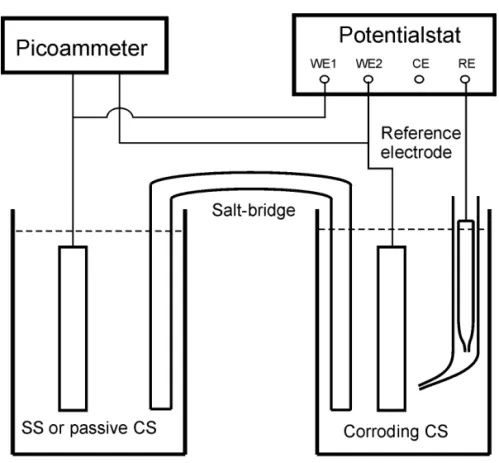
The macrocell corrosion experiments were carried out using a setup consisting of two electrochemical cells that are connected by a salt bridge as shown in Figure 5. This setup is designed to simulate the galvanic coupling of two steels in concrete and to study mechanistically the correlation between microcell corrosion and macrocell corrosion after the latter is formed. The electrical resistance of the salt bridge can be easily controlled and modified by changing the concentration of the electrolyte in it. The salt bridge was made of a U-shaped glass tube with an internal diameter of 9.4 mm or 3.1 mm (depending on the type of experiments). The two ends of
the U-shaped glass tube were sealed with a Celgard® 2500 microporous membrane to prevent solution flow and to reduce the chloride ion diffusion. The glass tube was filled with saturated Ca(OH)2 solution with or without 3% NaCl depending on the experimental conditions. The macrocell current between two electrodes (in a 1:1 ratio of apparent surface areas) was measured and recorded using a Keithley 485 picoammeter connected to a PC computer.
The linear polarization technique was used to determine the electrochemical polarization resistance (Rp) and the corrosion rate (icorr) of the electrodes in the electrochemical cell. The
potential of the steel electrode was scanned at a rate of 0.01 mV/s. The measurements were initiated at 10 mV below the corrosion potential (Ecorr) and terminated at 10 mV above it, while
recording the polarization current. The RP was defined as the slope of a potential-current density plot at the potential of Ecorr. The icorr is calculated from the following equation:
P corr
R B
i = (12) where B is the Stern-Geary constant that is related to the Tafel slopes for the anodic and cathodic reactions. The open circuit potential was recorded before every measurement. Sufficient time was allowed between the measurements for the steel electrodes to fully depolarize. The linear polarization and potential dynamic measurements were carried out using a Solartron 1480 multistat or solartron SI 1287 electrochemical interface, which was controlled by a computer using Corr-Ware software.
3.2. Tests in concrete specimens
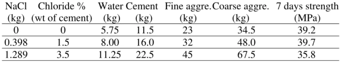
In addition to the above mechanistic study, macrocell current measurements were carried out on different pairs of reinforcing bars (rebars) in concrete specimens with a size of 20 × 15 × 8 cm3
. The composition of the concrete mixtures (including NaCl) and the compressive strength of the prismatic specimens are listed in Table 1. The specimens were cured for 35 days in a 95% ±5% relative humidity (RH) and 22oC ± 2oC environment. Two parallel rebars were embedded in each specimen. The two ends of the rebars were coated with epoxy resin and covered by a shrinkable
sleeve, leaving a length of 15 cm (surface area ≈70.7 cm2
) exposed to the concrete. The two rebars were connected by an external wire.
The concrete samples were then put in an environmental chamber, in which the RH was kept at 80% and the temperature cycled between 25oC and 45oC daily (four hours of temperature increase from 25oC to 45oC, eight hours of constant temperature at 45oC, four hours of temperature decrease from 45oC to 25oC, and then eight hours of constant temperature at 25oC) to accelerate the corrosion process of the rebars. The high temperature was changed from 45oC to 50oC during the stage corresponding to days 220 and 300 to accelerate further the corrosion process. The macrocell current between these two rebars was measured by using a Keithley 485 picoammeter. The coupling potential was measured using a Keithley 617 multimeter and a copper/copper sulfate (Cu/CuSO4) reference electrode (converted relative to SCE). Both measurements were carried out on a weekly basis and an average of three samples were used in the analysis.
4. Results and discussion
4.1. Macrocell corrosion between passive and active carbon steels
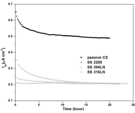
In order to study mechanistically the macrocell corrosion, the macrocell current density was directly measured between two electrodes having one to one surface areas after a corroding carbon electrode was connected with a passive carbon electrode in the electrochemical cells. In Figure 6, the line with solid symbols was the macrocell current density measured between a corroding CS electrode (Ecorr = –0.55 V) and a passive CS eletrode.It showed that the macrocell current rate decreased gradually with time until it reached a stable value after the initial pulse, which was due to charging of double layer capacitors in the interface of electrolyte/electrodes.
The macrocell current density can also be deduced from the polarization curves yielded by the two electrodes. This provided a tool to verify the measured macrocell current density. Figure 7 shows that the cathodic polarization curve of the passive CS intersects with the anodic polarization curve of corroding CS electrodes. If the effect of the IR drop (potential drop in the
salt bridge) is negligible, the intersection point provides the macrocell corrosion potential (≅ Ecorr of corroding electrode) and the corresponding current density. However, if a correction is made for the IR drop (i.e. Ecorr – IR), then the macrocell corrosion potential at the cathode is more positive than the intersection point.
Table 2 presents the measured and calculated macrocell current densities for two corroding CS electrodes (Ecorr = –0.55 V and –0.6 V vs. SCE) when coupled with a passive CS electrode,
respectively. The results show that the calculated macrocell current values were very close to the measured values after correction for the IR drop. It is confirmed that the macrocell current density calculated based on the polarization curves was reliable.
Table 3 lists the measured microcell corrosion rate, macrocell current density, and their proportions for three corroding CS electrodes when they were coupled with a passive CS electrode, respectively. The three corroding CS electrode with different corrosion potentials (Ecorr = –0.6 V, –0.55 V, –0.42V vs SCE) represented different corrosion conditions of the reinforcing steel. For the electrode with the corrosion potential of –0.6 V vs SCE, the microcell corrosion rate measured by a linear polarization technique was 13.3 ±0.4 μA/cm2
, and the macrocell current density was imac=0.53 μA/cm2. As mentioned earlier, Δicorr was about 60% of imac, and therefore the increase in corrosion rate caused by the macrocell effect was about 2.4%, as shown in Table 3. The results illustrate that microcell corrosion was the dominant corrosion process on the corroding carbon steel.
When Ecorr at the corroding electrode changed to a less negative potential, from –0.60 V to –0.42 V, both the microcell and macrocell current densities at the corroding electrode became lower. The percentage increase in the corrosion rate due to the macrocell effect was also reduced. This indicates that the effect of macrocell corrosion would diminish with an increase in Ecorr
while the microcell corrosion would increasingly dominate the whole corrosion process.
The above results provide a quantitative evaluation of the macrocell and microcell corrosion rates caused by the galvanic coupling between the corroding and passive carbon steels, based on the 1:1 electrode ratio. It is more applicable for reinforcing steel with relative large corrosion
areas since the non-corroding area on surrounding rebars are in similar or comparable size. However for pitting corrosion, which produces a very small corrosion area (such as pin holes), the non-corroding area on surrounding rebars could be relatively large and the effect of macrocell corrosion could become very important in the form of corrosion.
4.2. Macrocell corrosion between stainless steel and carbon steel
Stainless steel, with its superior corrosion resistance, has a chloride threshold that can be five to eight times higher than that of carbon steel [20]. The use of stainless steel reinforcement in patch repair areas could be a viable option for reducing repeated repairs in vulnerable areas and extending the service life of concrete structures. However, the risk of macrocell corrosion between two different metals has been a major concern that prevented this approach from being used in the field.
Since stainless steel has a much higher chloride corrosion threshold, it is very likely to become polarized cathodically when coupled with carbon steel. The macrocell current density between stainless steel and passive carbon steel is not a concern because these two steels can be polarized each other without causing significant macrocell current when they are both in the passive condition. The macrocell corrosion between stainless steel and corroding carbon steel would however be of concern.
The macrocell current density between stainless steel (2205, 304LN and 316LN) and corroding carbon steel electrode measured in the electrochemical cell are presented in Figure 6 with empty symbols. The macrocell current densities gradually approached a stable value after the initial pulse. From these results, it can be seen that the macrocell current density between the corroding carbon steel and stainless steel was less than half of that between the corroding carbon steel and the passive carbon steel. The galvanic coupling effect introduced by stainless steel was smaller because the rate-determining step of the macrocell corrosion process is a cathodic reduction reaction on stainless steel, which is significantly lower than that on passive carbon steel. Therefore, the use of stainless steel reinforcement in patch repair areas that are reinforced by
carbon steel will not increase the risk of corrosion on the carbon steel reinforcement, even when these bars are in direct (electrical) contact.
4.3. Macrocell current tested in concrete specimens
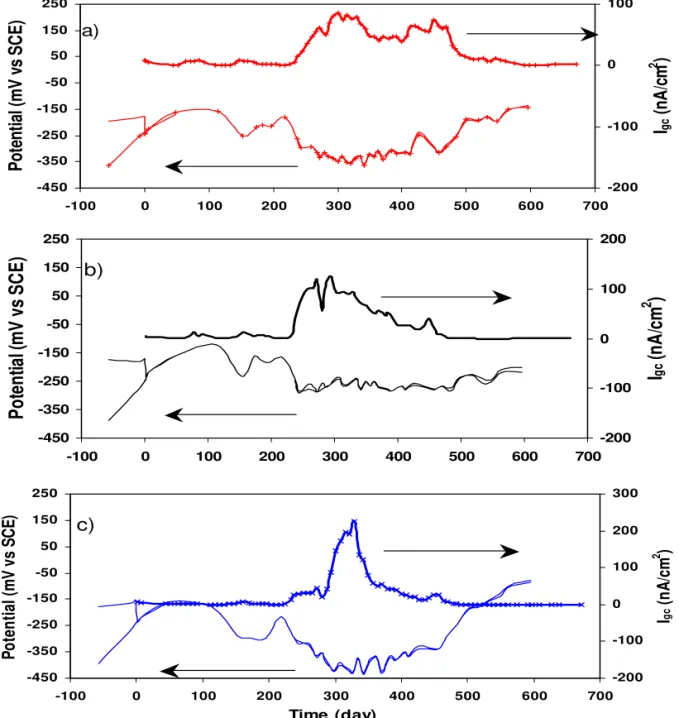
The macrocell current was measured in concrete specimens between corroding CS and passive CS or stainless steel. Figure 8shows the galvanic coupling potential and macrocell current of the corroding carbon steel in concrete containing 1.5% chloride, coupled with stainless steel in the presence of 3.5% chloride ions. Before the two rebars were connected, the open-circuit potential of the carbon steel was more negative than that of the SS. Since the carbon steel was in the concrete containing 1.5% chloride ions, it was likely becoming active due to attack by chloride ions. After the two rebars were connected, the coupling potential was about –0.15 V to –0.25 V over 220 days (see Figure 8), while the temperature cycle was between 25oC and 45oC. During this time, the macrocell current densities were relatively low (about a few nA/cm2), indicating no significant macrocell current, even though the carbon steel was in the concrete containing 1.5% chloride ions. The current pulse, which was observed in the electrochemical cell, did not appear because the small initial potential difference between the electrodes and the high electrical resistivity of concrete compared with the electrolyte in the cell. After 220 days, the upper temperature was changed from 45oC to 50oC, causing the coupling potential to shift to more negative values (about -0.35 V), and the macrocell current density to increase from 5 nA/cm2 to 80, 120 and 200 nA/cm2 for stainless steels 2205, 304LN and 316LN, respectively. The gradual decrease in the igc that occurred after this high current density period as shown in Figure 8 was
due to the formation of cracks in the concrete around the corroding carbon steel rebars.
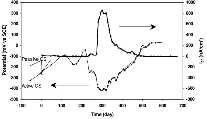
The galvanic coupling potential and the macrocell current density measured from the active carbon steel coupled with the passive carbon steel are shown in Figure 9. Two carbon steel rebars were embedded in each concrete specimen, one in chloride-free concrete and the other in concrete containing 1.5% chloride ions. During the first 220 days, the coupling potential fluctuated around –0.15 V, and the coupling current density remained very low (<10 nA/cm2
). After 275 days, the coupling potential dropped to –0.4 V, and the coupling current density
increased rapidly to 800 nA/cm2 then decreased to a very small value. This current density decrease was due to concrete cracking near the rebars.
These results show that the macrocell current density between active and passive carbon steels was much higher than that between active carbon steel and stainless steel, even when the stainless steel was in concrete containing a 3.5% concentration of chloride ions. This confirms the results measured in the electrochemical cells, which found that for the case of stainless steel coupled with corroding carbon steel, the macrocell current density was much lower (about 200 nA/cm2) than in the case of coupling between passive and active carbon steel (about 500 nA/cm2). Therefore, the use of stainless steel instead of carbon steel reinforcement in patch repair areas would not increase the risk of corrosion in the carbon steel reinforcement.
4.4. Effect of electrical resistance
Concrete electrical resistance can have a considerable effect on the rate of macrocell corrosion in reinforced concrete. With the increase of this concrete resistance, the potential drop between the two coupled steels can increase, resulting in a smaller rate of macrocell corrosion. This was demonstrated by the experiment performed in the electrochemical cell with different salt bridge resistances.
Table 4 shows the change in the values of imac with the resistance of the salt bridge, measured by
galvanic coupling experiments in an electrochemical cell. When the resistance of the salt bridge was increased from 0.9 KΩ to 33.0 KΩ, imac of the coupling between the passive and corroding
carbon steel electrodes decreased from 0.44 μA/cm2 to 0.18 μA/cm2. Obviously, the percentage of the corrosion rate due to the macrocell effect is decreased, correspondingly. This indicates that the macrocell corrosion effect can be reduced in concrete with high resistivity.
The change in resistance values in electrochemical cells from 0.9 kΩ to 33.0 kΩ cover a wide range of concrete resistance and corresponds to a wide range of rebar corrosion rates (from low to high). Therefore, changes in imac with an increase in the resistance of the salt bridge have a
practical implication for reducing the macrocell corrosion by increasing the electrical resistivity of concrete.
5. Conclusions
This paper presented a theoretical analysis and an experimental study of the relationship between macrocell and microcell corrosions in patch repairs of concrete structures. Based on the results, the following conclusions can be drawn.
1. A quantitative comparison was made for the macrocell and microcell corrosion rates for the coupling between corroding and passive carbon steels based on a 1:1 apparent electrode surface ratio. Microcell corrosion was found to be the dominant corrosion process on the corroding carbon steel when coupled with passive carbon steel.
2. The effect of macrocell corrosion is less significant when the corrosion potential of the corroding electrode becomes less negative. However, the effect of macrocell corrosion can become important when the area of active steel is very small compared with the area of passive steel.
3. The magnitude of macrocell corrosion decreases with increase in the resistance of the salt bridge in the electrochemical cell. This confirms that the effect of macrocell corrosion is reduced in the reinforced concrete with high resistivity.
4. The cathodic reduction current on stainless steel is significantly lower than that on passive carbon steel, leading to a lower macrocell current density induced by stainless steel when it is electrically connected with corroding carbon steel.
5. The experiments carried out in concrete specimens confirmed that the macrocell current density between stainless steel and active carbon steels was much lower than that between active and passive carbon steels (even when the stainless steel was in concrete containing 3.5% chloride ions). Therefore, the use of stainless steel reinforcement in patch repair areas within the concrete
structure already reinforced by carbon steel will not increase the corrosion risk on carbon steel reinforcement even when these bars are in direct (electrical) contact. It implies that the use of stainless steel instead of carbon steel reinforcement in repair areas can be a cost effective approach to reduce the frequency of repairs and extend the service life of reinforced concrete structures.
6. Acknowledgment
Grateful acknowledgment is made to The Nickel Institute, Alberta Transportation, The City of Ottawa, The Ministère des Transports du Québec and Valbruna Canada Ltd. for their contributions and support for this research project.
7. References
[1] Schieβl P, Breit W. Local repair measures at concrete structures damaged by
reinforcement corrosion – aspect of durability. International Symposium on Corrosion of Reinforcement in Concrete Construction, Royal Society of Chemistry; 1996. SP 183: 327-336.
[2] Li G, Yuan YS. Electrochemical incompatibility for patch-repaired corroded reinforced concrete. Journal of China University of Mining and Technology; 2003. 32: 44-47.
[3] Wheat HG, Harding KS. Galvanic corrosion in repaired reinforced concrete slabs-an update. Materials Selection and Design; 1993. 5: 58-62.
[4] Pruckner F, Gjφrv OE. Patch repair and macrocell activity in concrete structures. ACI Materials Journal; 2002. 99: 143-148.
[5] Castro P, Pazini E, Andrade C, Alonso C. Macrocell activity in slightly
chloride-contaminated concrete induced by reinforcement primers. Corrosion; 2003. 59: 535-546. [6] Raupach M. Chloride-induced macrocell corrosion of steel in concrete--theoretical
background and practical consequences. Construction and Building Materials; 1996. 10: 329-338.
[7] Andrade C, Maribona IR, Feliu S, Gonzalez JA, Feliu SJr. The effect of macrocells
between active and passive areas of steel reinforcement. Corrosion Science; 1992. 33: 237-249.
[8] Concrete Repair Guide, ACI 546 R report, American Concrete Institute.
[9] Emberson NK, Mays GC. Significance of properties mismatch in the patch repair of structural concrete Part 1 properties of repair systems. Magazine of Concrete Research; 1990. 42: 147-160.
[10] Emmons PH, Vaysburd AM. Corrosion protection in concrete repair: myth and reality. Concrete International; 1997. 19: 47-56.
[11] Gu P, Beaudoin JJ, Tumidajski PJ, Mailvaganam NP. Electrochemical incompatibility of patches in reinforced concrete. Concrete International; 1997. 19: 68-72.
[12] Jones DA. Principles and prevention of corrosion, 2nd ed; 1992. Prentice Hall.
[13] McDonald DB, Sherman MR, Pfeifer DW, Virmani YP. “ Stainless steel reinforcing as corrosion protection,” Concrete International; 1995. 17(5), p 65-70.
[14] Bertolini L, Pedeferri P. “Laboratory and field experience on the use of stainless steel to improve durability of reinforced concrete”, Corrosion Reviews; 2002. 20(1-2), p 129-152. [15] Clemeña GG, Virmani YP. “Comparing the chloride resistances of reinforcing bars.”
Concrete International; 2004. 26(11). 39-50
[16] Broomfield JP, « Field measurement of the corrosion rate of steel in concrete using a microprocessor controlled unit with a monitored guard ring for signal confinement », Techniques to assess the corrosion activity of steel reinforced concrete structures, ASTM STP 1276, Berke NS, Escalante E, Nmai CK, Whiting D eds., American Society for Testing and Materials, 1996, p. 97.
[17] Kabanov B, Burshtein R, Frumkin A. Discuss. Faraday Soc.; 1947, 1 pp.259.
[18] Qian SY, Qu D, Coates G. "Galvanic coupling between carbon steel and stainless steel reinforcements," COM2005, Materials Degradation: Innovation, Inspection, Control and Rehabilitation (Calgary, Alberta, August 21, 2005), pp. 99-117, August 01, 2005. [19] Abreu CM, Cristobal M J, Montemor MF, Novoa XR, Pena G, Perez MC. “Galvanic
coupling between carbon steel and austenitic stainless steel in alkaline media,” Electrochimica Acta.; 2002.47(13-14), 2271-2279.
[20] Bertolini L, Bolzoni F, Pastore T, Pedeferri P. Behaviour of stainless steel in simulated concrete pore solution, British Corrosion Journal; 1996, Vol. 31, No. 3, pp 218-222.
Fig. 1. Anodic (A) and cathodic (C) polarization curves of a passive reinforcing steel.
Fig. 2. Anodic (A), cathodic (C) and limiting cathodic (B) polarization curves of a corroding reinforcing steel.
A
C
E
corri
corrLog (i)
Pot
ent
ial
+
-A
C
E
corri
corrB
Pot
ent
ial
+
Log (i)
-A
C
E
corr 1i
corr 1A
C
E
corr 2i
corr 2Fig. 3. Macrocell current formed between passive steel (1) and corroding steel (2) when these two steels are in electrical contact in electrolyte.
E’
i
a2’
i
c2’
i
a1’
i
c1’
+
Pot
ent
ial
Log (i)
A
C
1E
corr 1i
corr 1A
C
2E’
E
corr 2i
corr 2Fig. 4. Macrocell current formed between two passive steels when these two steels are in electrical contact in electrolyte
i
a2’
i
c2’
i
a1’
i
c1’
+
Log (i)
Pot
ent
ial
Fig. 6. Galvanic current density of corroding CS coupled with different steels in a saturated Ca(OH)2solution.
Fig. 7. Polarization curves of corroding CS, passive CS and SS 316LN measured in a saturated Ca(OH)2solution.
-450 -350 -250 -150 -50 50 150 250 -100 0 100 200 300 400 500 600 700 Po te nt ia l (m V v s SC E) -200 -100 0 100 Igc (n A /c m 2 ) a) -450 -350 -250 -150 -50 50 150 250 -100 0 100 200 300 400 500 600 700 P o te n tia l (m V v s S C E ) -200 -100 0 100 200 Igc (n A /c m 2 ) b) -450 -350 -250 -150 -50 50 150 250 -100 0 100 200 300 400 500 600 700 Time (day) Po te n ti al ( m V v s SC E) -200 -100 0 100 200 300 Igc (n A /c m 2 ) c)
Fig. 8. Galvanic coupling potential and current densities measured in concrete specimens for CS in 1.5% Cl-coupled with a SS alloy in 3.5% Cl-: a) SS 2205; b) SS 304LN; c) SS 316LN.
-500 -400 -300 -200 -100 0 100 200 300 400 -100 0 100 200 300 400 500 600 700 Time (day) Potential (mV vs SCE ) -800 -600 -400 -200 0 200 400 600 800 1000 Igc (nA/cm 2 ) Passive CS Active CS
Fig. 9. Galvanic coupling potentials and current densities measured in concrete specimens for CS in 1.5% Cl-coupled with passive CS in chloride-free environment.
Table 1 Composition of Concrete Specimens for Galvanic Coupling Tests. NaCl (kg) Chloride % (wt of cement) Water (kg) Cement (kg) Fine aggre. (kg) Coarse aggre. (kg) 7 days strength (MPa) 0 0 5.75 11.5 23 34.5 39.2 0.398 1.5 8.00 16.0 32 48.0 39.7 1.289 3.5 11.25 22.5 45 67.5 35.8
Table 2 Measured and calculated igc values for various corrosion potentials at the corroding electrode
igc (μA/cm2)
Ecorr at corroding electrode Measured Calculated(Ecorr) Calculated(Ecorr -iR)
−0.55 V 0.44 0.52 0.48
Table 3 Relationship between macrocell and microcell current densities for passive carbon steel coupled with corroding carbon steel at different Ecorr (vs SCE)
Ecorr at corroding electrode imac (μA/cm2 ) imic (μA/cm2 ) imac/imic (%)
Δicorr/icorr (%)
−0.60 V 0.53 13.3 4.0 2.4
−0.55 V 0.44 12.8 3.4 2.0
−0.42 V 0.04 1.42 2.8 1.7
Table 4 Measured macrocell current density, imac, in electrochemical cells with different salt bridge resistances
Resistance of salt bridge (kΩ) 0.9 2.3 33