HAL Id: hal-01844064
https://hal.umontpellier.fr/hal-01844064
Submitted on 7 Sep 2018
HAL is a multi-disciplinary open access
archive for the deposit and dissemination of sci-entific research documents, whether they are pub-lished or not. The documents may come from teaching and research institutions in France or abroad, or from public or private research centers.
L’archive ouverte pluridisciplinaire HAL, est destinée au dépôt et à la diffusion de documents scientifiques de niveau recherche, publiés ou non, émanant des établissements d’enseignement et de recherche français ou étrangers, des laboratoires publics ou privés.
Review on Types of Root Failures in Shallow Landslides
Ana Sofia Dias, Marianna Pirone, Gianfranco Urciuoli
To cite this version:
Ana Sofia Dias, Marianna Pirone, Gianfranco Urciuoli. Review on Types of Root Failures in Shal-low Landslides. 4th World Landslide Forum 2017, May 2017, Ljubljana, Slovenia. pp.633-640, �10.1007/978-3-319-53498-5_73�. �hal-01844064�
1
[Preprint]
Review on Types of Root Failures in Shallow Landslides
Ana Sofia Dias
1,2, Marianna Pirone
1, and Gianfranco Urciuoli
11Department of Civil, Building and Environmental Engineering, University of Naples Federico II, Via
Claudio 21, 80125 Naples, Italy
2AMAP, INRA, IRD, CNRS, CIRAD, University of Montpellier, Montpellier, France
May 29, 2017
Conference: Workshop on World Landslide Forum
Title of the book: Advancing Culture of Living with Landslides
Abstract
Nowadays the interest of geotechnical engineers for green solutions is being developed and the use of vegetation as a reinforcement to improve slope stability is growing. The sliding surface of shallow landslides tends to not exceed 1.5–2 m depth, and as a consequence it can be crossed by roots that, in this case, work as a stabilizing measure. Therefore, the study of the soil-roots interaction is necessary to quantify the contribution of vegetation to the stability of shallow landslides. The goal of this paper is to provide an overview of the root failure mechanisms that can occur along the sliding surface and of the forces applied by roots, in order to evaluate the safety factor of a reinforced slope. Several prevailing stress states occur along a shallow landslide failure surface: tension stress at the slide crest, shear stresses along the base of the unstable soil layer and passive earth pressures at the slope toe. Some considerations are also made regarding acceptable simplifications, in terms of root geometry and soil-root friction strength, that are currently assumed in the literature.
Keywords
Root reinforcement, Root-soil interaction, Root failure mechanisms, Shallow landslides
Introduction
Introducing vegetation in a slope can be considered a stabilization measure, as a result of the beneficial hydro-mechanical effects of plants on preventing shallow landslides. In that case, the sliding surface occurs within the first 1.5–2 m from the ground surface where the plants’ roots can penetrate (Wu 1976; Schwarz et al. 2010b; Burylo et al. 2011). For this reason the assessment of the efficiency of such measure is an interesting task for geotechnical engineers, but it is possible only if the root failure mechanics are clearly understood.
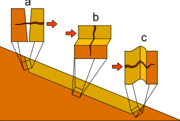
The current review is mainly devoted to investigate the mechanical response of the roots’ fibres to different types of stresses acting in a slope, focusing on those occurring along a shallow landslide (Fig.
2
1). Roots may be stressed by (a) pull out forces, (b) shear ones or (c) compression ones (Schwarz et al. 2015). In general, the root in the situations (a) and (b) may slip out or break depending on the soil and root types, moisture and root-soil friction (Ennos 1990; Mickovski et al. 2007; Pollen 2007). In situation (c), Wu et al. (1988) and Schwarz et al. (2015) showed that the most common mechanism is the occurrence of buckling, even though root bending or root tension for larger displacements may be observed. However, the mechanisms previously appointed are complex and depend on the root interaction with the surrounding soil, as well as on root features. Much investigation is still required on this topic, Mao et al. (2014) stated that the mechanisms by which vegetation roots mechanically interact with soil are still not well described.
Fig. 1 Stresses acting on root reinforcement along the sliding surface of a shallow landslide: a tensile, b shear and c compression stresses
In this paper, first the description of the root-soil interaction, root resistance and stiffness will be introduced, then a description of the main root failure modes is presented.
Root-Soil Coupling
Soil-Root Frictional Strength
The root-soil friction strength depends on the type of soil, soil moisture and confining pressure around the root (Pollen 2007; Mickovski et al. 2007; Bourrier et al. 2013; Veylon et al. 2015) and can be calculated following different approaches.
Referring to an ideal straight smooth fibre, as a basic ingredient for the analysis, the soil-root friction
𝜏𝑏, or so-called bond or interface friction stress, was suggested to be given by (1) in the works of Gray
and Ohashi (1983) and Cazzuffi et al. (2014), as it had been assessed in the previous work of Potyondy (1961). In Eq. (1), 𝑧 is the depth of the root from ground surface, 𝛾 is the soil unit weight, 𝑓 is a reductive coefficient (0.7–0.9) modelling the root-soil interface and 𝜙′ is the internal friction angle of the soil. Ennos (1990), on the other hand, considered that 𝜏𝑏 was constant in depth, given by (2),
where 𝜏 is the soil shear strength near the root and 𝛼 is the relative strength of the root-soil bond (0 ≤ 𝛼 ≤ 1). This was a reasonable approximation because the roots studied by Ennos presented lengths up to 5 cm.
𝜏𝑏 = 𝑧 𝛾 (1 − sin 𝜙′) 𝑓 tan 𝜙′ (1)
𝜏𝑏 = 𝛼𝜏 (2)
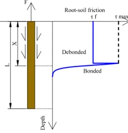
In the research of Naaman et al. (1991) on fibres subjected to pull out load, a mathematical model that describes the response of straight smooth fibres was developed. A distinction between two types of friction, static and dynamic, is made (Fig. 2). The static friction, or bonded, is mobilized when the root is being stretched and is essentially regulated by the peak strength of the soil. Once the root starts to slip out, friction is essentially regulated by the ultimate shear strength of the soil (critical or
3
residual one). It becomes constant along the fibre taking the value of dynamic friction, or debonded friction. The debonded friction is determined by the following phenomena: the pull out force applied to the root strongly modifies the stresses in the shallow subsoil, causing the detachment of the root from the soil and a decrease of the root diameter (Poisson’s effect), as well as a decrease of the confining stress around the root (Naaman et al. 1991) that reduces the bonded effect, supporting the assumption of Schwarz et al. (2010a). Cazzuffi et al. (2014) always consider the debonded friction even if the root-soil bond is still intact.
Fig. 2 Mobilized root-soil friction along the depth of the root
The static friction was ignored by Schwarz et al. (2010a) after showing that it represents a small percentage of the total friction. The friction values calculated using (1) and (2) are not a bonded friction, but an alternative way of calculating debonded friction for shallow root systems; in particular Eq. (1) provides constant values of 𝜏𝑏 for roots developing in horizontal direction.
Even in Schwarz et al. (2010a), the debonded friction was simply calculated using Mohr-Coulomb equation. However, the variation of the normal stress with depth (increase of overburden pressure) cannot be ignored in case long vertical roots are considered.
A positive correlation between the root additional resistance and the vertical effective confining stress is reported in the work of Liang et al. (2015). As mentioned by this author, for deeper rooting systems, the normal effective stress varies significantly due to the deeper embedding depth.
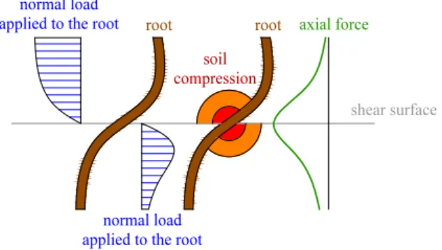
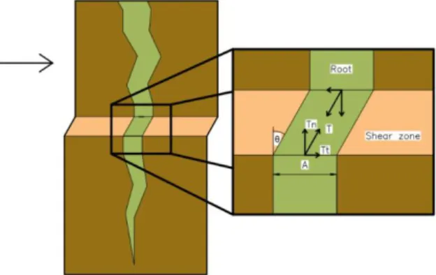
Moreover, normal stress may also vary along the periphery of a root when the applied force presents an horizontal component (e.g. when the root intersects the sliding surface, Fig. 3). For this reason the friction will be greater on one side of the root and may be smaller (or null) in the other, as a consequence of the root deformation (Nghiem et al. 2003; Belfiore and Uriciuoli 2004). Even detachment of the root from the soil may occur in cohesive soils, Wu et al. (1988). Evidence is presented in the numerical analysis of Dupuy et al. (2005), Vergani et al. (2014), Wu (2013) and Bourrier et al. (2013) that show the stresses in roots’ surrounding soil.
4
Fig. 3 Scheme of the root deformation due to the shear of the soil layer (the upper layer moves towards the right on the
lower one). The normal load acting on the root’s axis, compression in the soil and tensile axial force in the root are
represented
In Fig. 3 the deformation of a root crossing a soil layer subjected to shear and to a relative displacement along a sliding surface is presented; the load applied normally to the axis of the root and the tensile axial force are also indicated.
Tortuosity Effect
A typical response to a pull out force applied to a root embedded in the soil is presented in Fig. 4, in which four phases can be identified. Displacements of the initial phase are a consequence of the root straightening corresponding to a small force. Then, the root material strength is effectively mobilized. However, at the initial rearrangement of the root geometry, generally strains up to 5% can take place (Schwarz et al. 2010b), representing a critical issue in slope stability problems.
Fig. 4 Scheme of the tensile stress acting in the root during pull out with the indication of different mechanisms of failure (III and IV)
In Fig. 4, the Young’s modulus of the root in the phase I is apparent and lower than in phase II, because the root is being straightened. This is also known as the tortuosity effect, described by Commandeur and Pyles (1991), as an influence of the root geometry on the macroscopic elastic behaviour of a pulled root.
For Schwarz et al. (2010b), the effect is considered the form of apparent Young’s modulus (𝐸𝑎𝑝𝑝) by
multiplying the Young’s modulus of straight roots, which is equal to Young’s modulus of the root material (𝐸𝑚), by an empirical reductive coefficient (𝑟) that can vary from 0 to 1, as presented in (3).
This relation is only applied in case the strain is less than the threshold value corresponding to the end of straightening. Both reductive coefficient and threshold value depend on root tortuosity and soil conditions, such as soil type, confining pressure and water content.
𝐸𝑎𝑝𝑝= 𝑟𝐸𝑚 (3)
After the root is straightened, the increase of load tensioning the root is transferred gradually to the soil through friction (phase II of Fig. 4). During the mobilization of this frictional resistance there is no
5
appreciable extension of the root and the Young’s modulus increases (Schwarz et al. 2010b). To describe the variation of the Young’s modulus with strain (𝜀), Eq. (4) is used, where 𝐸𝑎𝑝𝑝 is the apparent
Young’s modulus of progressively activated root length, 𝐸(𝑑) is the Young’s modulus of the root of diameter 𝑑, and 𝛽 and 𝜔 are fitting parameters derived from laboratory experiments.
𝐸𝑎𝑝𝑝= 𝐸(𝑑)𝛽𝜀−𝜔 (4)
Simplifying the previous approaches, the secant Young’s modulus is used in Schwarz et al. (2013), as the ratio of root strength over strain at failure. Nevertheless, this operation does not affect the estimation of the maximum tensile load of a root, only the value of strain at which the maximum force is observed, as highlighted by the author.
Root Failure Modes
Pull Out
Gray and Leiser (1996) highlighted that if the fibres are very short, unconstrained and subjected to low confining stresses, they will tend to slip out when the root is tensioned. In fact, when a root is pulled, shear friction between the root and soil takes place, and the failure occurs either by the root-soil bond or by the root-soil. Nevertheless, roots will continue to contribute to the root-soil reinforcement, as observed in phase IV of Fig. 4, depending on the contact area between root and soil that decreases with the removal of the root.
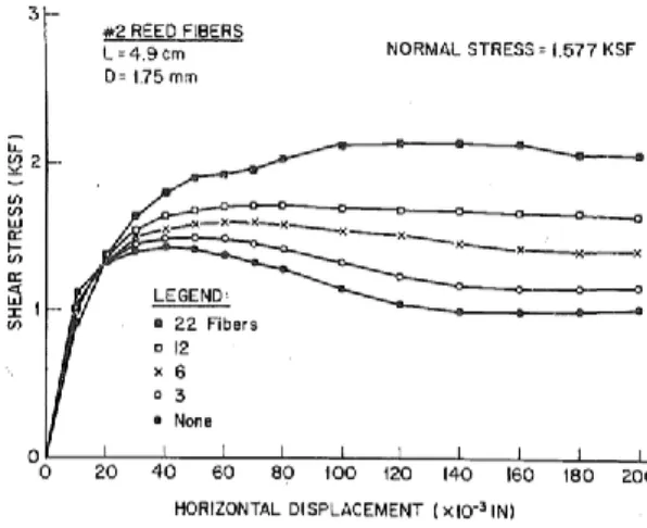
Gray and Ohashi (1983) studied the mechanics of fibre-reinforced soil and showed the importance of the mechanisms of root stretching and root pulling out. During the direct shear test carried out by these authors, none of the fibres immersed in the tested sand broke in tension. Indeed, they either pulled out or stretched depending upon the confining stress and length. Back calculations revealed that in those tests less than 25% of the tensile strength of the fibres was mobilized. In those direct shear tests, Gray and Ohashi (1983) observed that the fibre-reinforced soil tended to increase the ultimate shear strength of the composite material, and to limit reductions in post peak shearing resistance (the material becomes more stable and ductile), as in Fig. 5. As a consequence of these results, Gray and Ohashi (1983) classified the roots as ideally extensible inclusions, i.e. inclusions characterized by failure strains larger than the maximum strains in the soil without inclusions, allowing a greater ductility of the composite material (Dupuy et al. 2005).
Fig. 5 Stress strain curve of fibre-reinforced soil (1 ksf = 47.9 kN/m2) (Gray and Ohashi 1983)
The force, 𝐹𝑃, necessary to break the root-soil bond (also known as pull out resistance) is given by (5),
6
𝐹𝑃= 𝜋𝑑𝐿𝜏𝑝 (5)
To be noticed that in the work of Schwarz et al. (2010a), a great advance was achieved by considering the evolution of root diameter (𝑑) with length and root tortuosity. This has been ignored by many authors, such as Ennos (1990) and Gray and Leiser (1982). The use of constant diameter could become a rough approximation because the transmission of stress from root to friction in the soil varies, not only with the normal stress and soil frictional properties, but also with the available contact area between soil and roots. Therefore, with decreasing root diameter, there is less and less capability of transferring stresses to the soil, and consequently the root will pull out faster.
In the work of Schwarz et al. (2010a) a root of tortuous length 𝑙 (length along root axis) was discretised using elements of length 𝑏. Each of these elements presents a different diameter, which is function of the diameter of the root tip (𝑑0) and of a scaling factor (𝑠) called root diameter proportionality factor.
The total soil-root friction force in a root segment is dependent on its lateral surface area.
As reported in Dupuy et al. (2005) and Mickovski et al. (2007), the additional resistance due to the presence of branches along the studied root ranges from 0.1 to 5 N per branching point, depending on soil moisture and branching geometry. Once that the increase of resistance in presence of branches may not be despicable, Schwarz et al. (2010a) proposed that the maximum pull out force of a root (𝐹𝑝𝑙𝑏) is given by (6), where 𝑌 is an empirical branching coefficient (0.1 < 𝑌 < 1) and 𝑑𝑖 are the diameters
of each segment of the discretised root’s length (𝑖 segments).
𝐹𝑝𝑙𝑏 = 𝑏𝜏𝑝𝑑0𝜋 + (𝜋𝑏𝜏𝑝+ 𝑌) ∑ 𝑑𝑖 (6)
Nevertheless, roots interact among them in a root system leading to a superposition of shear stresses within the soil. To take into account this interaction Giadrossich et al. (2013) proposed (7) to obtain the global pull-out resistance of a bundle of 𝑛 roots, 𝑓𝑏𝑙𝑜𝑐. In this equation, 𝑤𝑖 is the radial distance
from the surface of one of the roots of the bundle to a given point 𝑥 in the surrounding soil. Therefore, the shape of a block of soil permeated by 𝑛 roots that is pulled out is obtained by determining the points 𝑥 where the soil strength is exceeded by 𝑓𝑏𝑙𝑜𝑐.
𝑓𝑏𝑙𝑜𝑐= 𝜏𝑝∑𝑑𝑖 𝑤𝑖 𝑛 𝑖=1 (7)
Breakage
A root breaks when the tensile load applied to the cross-section area exceeds its tensile strength, assuming that the root is well anchored in the soil. This way is observed in the phase III of Fig. 4, in which there is an abrupt drop in the root tension, with a null capacity during phase IV.
From experimental works on root tensile strength, 𝑡𝑟 (force distributed in the area of the cross section
of the root, in MPa), a simple empirical relation with root diameter with the form of a power-law was obtained. It is represented by (8), where 𝑑 is the root diameter at the section of breakage [mm] and the parameters 𝜁 and 𝜌 are calibration constants.
𝑡𝑟 = 𝜁𝑑𝜌 (8)
The experimental works showed that 𝜌 takes values always lower than zero because the roots with larger diameters present lower tensile strengths. Some experimental values can be found in the works of Gray and Ohashi (1983), Comino et al. (2010), Burylo et al. (2011) and Gray and Sotir (1996). Obviously, the root tensile load 𝐹𝐵 is given by (9). It may be of interest to mention that the strength
of roots decrease when the vegetation is removed. The computation of the root strength decay can be found in more detail in Cazzuffi et al. (2014).
7
Critical Length
According to Fig. 2, the increase of pull out force (𝐹) mobilizes friction on increasing root length. If that force reaches the root tensile resistance (𝐹𝐵), the root breaks. If all the root-soil interaction
resistance is mobilized, then 𝐹 takes the value of the pull out resistance 𝐹𝑃. The critical length is
obtained by equalling (5)–(9) and it represents the separation of the occurrence of breakage from slippage. Therefore, in order to break, a root should have a length greater than the critical length 𝐿𝑐𝑟𝑖𝑡,
given by (10). Consequently, the critical length also represents the maximum length along which friction can be mobilized.
𝐿𝑐𝑟𝑖𝑡= 𝑡𝑟𝑑 4𝜏𝑝
(10) This threshold value depends on the frictional strength between roots and soil and on the tensile strength of the roots of the given species. Roots with small diameters tend to slip out and roots with larger diameters tend to break (Pollen 2007).
Buckling
Schwarz et al. (2015) investigated the influence of the roots on soil resistance under compression focusing on failure, due to passive earth pressures at the toe of a landslide. Moreover roots are also subjected to compression when root orientation is opposite to the movement of the unstable layer (Gray and Ohashi 1983; Wu et al. 1988).
However, the reinforcement provided by roots has been neglected, based on the assumption that the compressive strength of roots is low compared with that of soil (Cazzuffi et al. 2014). Nevertheless, it was found that the resistance of some roots in compression was of the same order of magnitude of the tensile one. For example, roots having diameters of 4 and 8 mm, failing at tensile forces of approximately 200 and 400 N could stand compression loads of 50 and 150 N, respectively, before buckling occurs (Wu et al. 1988).
In Wu et al. (1988), the measured values of critical load fell between the values predicted by the solutions of Toakley (1965) and Euler, solution 1 and 2, respectively (Fig. 6). Schwarz et al. (2015) suggested the use of the solution by Timoshenko and Gere (1961) in order to calculate the critical buckling load. Euler’s solution is represented by (11), provided that a more conservative estimation was obtained (Fig. 6), where 𝐿𝑏 is the length of the buckled root (between 3 and 10 cm for increasing
root diameter in Wu et al. 1988), 𝑛 is the mode number, 𝐸 is the Young’s modulus considered by the author, 𝐼 is the inertia of the root cross-section and 𝐹𝑐 is the critical load.
𝐹𝑐 =𝑛2𝜋2𝐸𝐼 𝐿𝑏2
8
Fig. 6 Measured critical load compared with the theoretical solutions (adapted from Wu et al. 1988)
Modelling
Physical Model
In the first models proposed in the literature, roots were assumed to be fibrous elements without shear and bending strength, presenting only tensile resistance, Wu (1976) and Gray and Ohashi (1983). It is generally accepted that roots present an elastic behaviour, as Comino et al. (2010), Burylo et al. (2011) and Vergani et al. (2014), among others, did.
In order to describe the behaviour of the roots subjected to shear, Wu (1976) proposed an analytical model. The shearing of the soil causes the root to distort, as presented in Fig. 7, originating elongation of the roots that result into tensile stresses, which act on the unstable soil volume as stabilizing external forces (Wu 1976; Gray and Ohashi 1983).
Fig. 7 Scheme of the stresses in the root during shear
This new representation of the tensile force in the fibre can be divided into a normal 𝜎𝑟 and tangential
𝜏𝑟 component to the shear plane, acting in the soil. The normal component 𝜎𝑟 increases the confining
stress on the failure plane, thereby mobilizing additional shear resistance in the soil, whereas the tangential component 𝜏𝑟 directly decreases the acting shear stress. The system of equations (12)
represents this decomposition assuming that the root out of the shear zone stays perpendicular to it (Wu 1976), where 𝜃 is the shear distortion of the root and 𝑡𝑟 is the tensile stress (Fig. 7).
{𝜎𝜏𝑟 = 𝑡𝑟cos 𝜃
𝑟 = 𝑡𝑟sin 𝜃
(12)
Beam on Elastic Foundation Model
Even though, many works assume that roots are cable elements whose only resistance is the tensile one, other authors investigated the bending and shear resistance of these elements. This is important not only for the case of large-diameter roots, where bending resistance can be mobilized, but also in order to describe the effect of soil movement on roots deformation, and the constrain of roots to the soil (Nghiem et al. 2003).
Nghiem et al. (2003) compared the behaviour of a root to an inclined pile, which solution in terms of stresses and strains is derived from a problem of beam on elastic foundation, however ignoring the bending resistance of the root. Wu et al. (1988) and Wu (2013) used cable and beam solutions for the same beam on elastic foundation problems. The comparison of the beam and cable models was produced by Mao et al. (2014), differentiating the behaviour of different types of roots. Wu (2013) suggested that the cable solution should be adopted when the tensile resistance of the root 𝑡𝑟 is much
9
greater than the flexure stiffness, 𝐸𝐼, i.e. when the product 𝜂𝐿 > 2.5. Conversely, the beam solution is the most adequate when 𝜂𝐿 < 1.5, where the parameter 𝜂 is given by (13).
𝜂 = √𝑡𝑟⁄ 𝐸𝐼 (13)
The generic beam on elastic foundation problem is described by (14), where 𝑢 is the displacement in the direction normal to the root axis, 𝑧 is the coordinate along the axis and 𝑝 is the soil reaction, which is the product between the displacement 𝑢 and the reaction constant.
𝐸𝐼𝑑4𝑢 𝑑𝑧4− 𝑡𝑟
𝑑2𝑢
𝑑𝑧2 = 𝑝𝑑
(14) The beam solution can be found in Wu et al. (1988). The ultimate load 𝑝𝑦 is given by (15), where 𝑐 is
the soil cohesion, 𝑁𝑐, 𝑁𝑞 and 𝑁𝛾 are bearing capacity numbers, 𝑞 is the lateral surcharge and 𝑝𝑦 is the
yielding reaction pressure of the soil on the root [limit of 𝑝 of (14)].
𝑝𝑦 = 𝑐𝑁𝑐+ 𝑞𝑁𝑞+ 1 2⁄ 𝛾𝑑𝑁𝛾 (15)
At large displacements, the depth of the plastic zone increases, which makes the flexible cable solution more adequate to describe the behaviour of the root, because the coupling between horizontal and vertical component of the tensile strength of a root should be considered (Wu et al. 1988). Due to the large deformations, the ultimate soil resistance 𝑝𝑦 given by (15) is mobilized along all the root. This
way, Wu et al. (1988) described the problem using (14) and adopted the flexible cable solution described by (16), where 𝑇(0) is the tensile force in the root at the shear surface and 𝑇(𝐿) is the tensile force at the tip of the root. For further details it is recommended to consult the work of Wu (2013).
{ 𝑇(0) sin 𝛼 = 𝑇(𝐿) 𝑝𝑦𝑑𝐿 = 𝑇(0) cos 𝜃 𝑢(0) =𝑝𝑦𝑑𝐿 2 2𝑇(𝐿) 𝑢(𝑧) =𝑇(0) cos 𝜃 𝐿 − 𝑝𝑦𝑑(2𝐿 − 𝑧)𝑧 2𝑇(𝐿) (16)
Investigation on the root-soil interaction when the soil is sheared was also made using numerical models. Mickovski et al. (2011) and Mao et al. (2014) used FEM and DEM to simulate the response of roots in a direct shear test, observing that the root reinforcement varied as a function of soil strain, and was closely related to root geometry, position in the soil and mechanical traits. On the other hand, Liang et al. (2015) considered the interaction between roots and soil using existing p-y curves for piles under lateral loading in a FEM model of a root, validated using experimental observations. It was concluded that the plastic deformations dominates over elastic deformations, because large relative soil-root deformations were found even for relatively small global slip of the rooted soil (Fig. 8). This means that the ultimate resistance of the soil surrounding the root is reached before the critical state of the soil. This also justifies the use of 𝑝𝑦 by Wu et al. (1988) in the beam solution. In fact, at shallow
depths, the soil was pressed against the root forming an upward moving wedge due to the low confining pressures. When the confining pressure increases, soil tends to contour the root.
10
Fig. 8 Comparison of the displacements observed in the soil and in roots of different diameter subjected to shear loading (adapted from Liang et al. 2015)
Conclusions
This review regards the mechanical effects of roots on shallow landslides, by identifying and describing the types of root failure that can occur in a slope. It was intended to provide basic knowledge on the loads that lead to root failure, so that geotechnical engineers can better consider root resistance for the improvement of slope stability analysis, in particular, with regards to shallow landslides.
Three main forms of root failure were identified: pull out, breakage and buckling. Nevertheless, soil-root interaction under shear actions and tortuosity effect are also considered.
The main observations made in this work are that:
- a better estimation of the pull out resistance may be obtained if the variation of root diameter with depth is considered, because the available contact area between soil and root that mobilizes friction varies;
- there is more than one way of calculating soil-root frictional resistance. However it depends on the normal stresses which are considered in a very simplified way, ignoring its variation along the root length. Importance is also given to the effect of root deformation under shear; - the comparison of roots to structural elements, such as beams and cables, provides an
improvement on the description of root response;
- the tortuosity effect is responsible for a great variation of the Young’s modulus of the root, which causes the root to mobilize its frictional resistance only after straightening;
- root under compression is still a less investigated topic, however it is generally accepted that a root tends to buckle.
Acknowledgements
The authors wish to acknowledge the support of the European Commission via the Marie Skłodowska-Curie Innovative Training Networks (ITN-ETN) project TERRE ‘Training Engineers and Researchers to Rethink geotechnical Engineering for a low carbon future’ (H2020-MSCA-ITN-2015-675762).
References
Belfiore G, Urciuoli G (2004) Analisi Del Contributo Meccanico Delle Radici Alla Resistenza Del Terreno. Incontro Annuale dei Ricercatori di Geotecnica 2004, 7–9 luglio 2004. Chieti, Italy (in Italian)
11
Bourrier F, Kneib F, Chareyre B, Fourcaud T (2013) Discrete modelling of granular soils reinforcement by plant roots. Ecol Eng 61:646–657
Burylo M, Hudek C, Rey F (2011) Soil reinforcement by the roots of six dominant species on eroded mountainous marly slopes (Southern Alps, France). CATENA 84:70–78
Cazzuffi D, Cardile G, Gioffrè D (2014) Geosynthetic engineering and vegetation growth in soil reinforcement applications. Transp Infrastruct Geotechnol 1:262–300
Comino E, Marengo P, Rolli V (2010) Root reinforcement effect of different grass species: a comparison between experimental and models results. Soil Tillage Res 110(1):60–68
Commandeur PR, Pyles R (1991) Modulus of elasticity and tensile strength of Douglas-fir roots. Can J For Resour 21:48–52
Dupuy L, Fourcaud T, Stokes A (2005) A numerical investigation into factors affecting the anchorage of roots in tension. Eur J Soil Sci 56(3):319–327
Ennos AR (1990) The anchorage of leek seedlings: the effect of root length and soil strength. Ann Bot 65(4):409–416
Giadrossich F, Schwarz M, Cohen D, Preti F, Or D (2013) Mechanical interactions between neighbouring roots during pullout tests. Plant Soil 367:391–406
Gray DH, Leiser AT (1982) Biotechnical slope protection. Van Nostrand Reinhold Co., New York Gray DH, Ohashi H (1983) Mechanics of fiber reinforcement in sand. J Geotech Eng 109(3):335–353 Gray D, Sotir R (1996) Biotechnical and soil bioengineering, slope stabilization. In: A practical guide for
erosion control. Wiley, NJ
Liang T, Knappett JA, Duckett N (2015) Modelling the seismic performance of rooted slopes from individual root–soil interaction to global slope behaviour. Géotechnique 65(12):995–1009 Mao Z, Yang M, Bourrier F, Fourcaud T (2014) Evaluation of root reinforcement models using
numerical modelling approaches. Plant Soil 381:249–270
Mickovski SB, Bengough AG, Bransby MF, Davies MCR, Hallett PD, Sonnenberg R (2007) Material stiffness, branching pattern and soil matric potential affect the pullout resistance of model root systems. Eur J Soil Sci 58(6):1471–1481
Mickovski SB, Stokes A, van Beek R, Ghestem M, Fourcaud T (2011) Simulation of direct shear tests on rooted and non-rooted soil using finite element analysis. Ecol Eng 37:1523–1532
Naaman AE, Namur GG, Alwan JM, Najm HS (1991) Fiber pullout and bond slip. I: analytical study. J Struct Eng 117(9):2769–2790
Nghiem MQ, Nakamura H, Shiraki K (2003) Analysis of root reinforcement at slip surface. J Jpn Landslide Soc 40(4):44–52
Pollen N (2007) Temporal and spatial variability in root reinforcement of streambanks: accounting for soil shear strength and moisture. CATENA 69:197–205
Potyondy JG (1961) Skin friction between various soils and construction materials. Geotechnique 11(4):339–353
12
Schwarz M, Cohen D, Or D (2010a) Root-soil mechanical interactions during pullout and failure of root bundles. J Geophys Res 115:1–19
Schwarz M, Lehmann P, Or D (2010b) Quantifying lateral root reinforcement in steep slopes—from a bundle of roots to tree stands. Earth Surf Proc Land 35(3):354–367
Schwarz M, Giadrossich F, Cohen D (2013) Modelling root reinforcement using a root-failure Weibull survival function. Hydrol Earth Syst Sci 17(11):4367–4377
Schwarz M, Rist A, Cohen D, Giadrossich F, Egorov P, Büttner D, Stolz M, Thormann J-J (2015) Root reinforcement of soils under compression. J Geophys Res Earth Surf 120:2103–2120
Timoshenko SP, Gere JM (1961) Theory of elasticity stability. McGraw-Hill, New York
Toakley AR (1965) Buckling loads for elastically supported struts. J Eng Mech (ASCE) 91:205–231 Vergani C, Schwarz M, Cohen D, Thormann J-J, Bischetti GB (2014) Effects of root tensile force and
diameter distribution variability on root reinforcement in the Swiss and Italian Alps. Can J For Res 44 (11):1426–1440
Veylon G, Ghestem M, Stokes A, Bernard A (2015) Quantification of mechanical and hydric components of soil reinforcement by plant roots. Can Geotech J 52:1839–1849
Wu TH (1976) Investigation of landslides on Prince of Wales Island, Alaska. Department of Civil Engineering, Ohio State University, Columbus, OH (Geotechnical Engineering Rep. 5. 94 p) Wu TH (2013) Root reinforcement of soil: review of analytical models, test results, and applications to
design. Can Geotech J 50:259–274
Wu TH, McOmber RM, Erb RT, Bear PE (1988) Study of soil-root interaction. J Geotech Eng 114(12):1351–1375