HAL Id: lirmm-02895512
https://hal-lirmm.ccsd.cnrs.fr/lirmm-02895512
Submitted on 13 Jul 2020
HAL is a multi-disciplinary open access
archive for the deposit and dissemination of
sci-entific research documents, whether they are
pub-lished or not. The documents may come from
teaching and research institutions in France or
abroad, or from public or private research centers.
L’archive ouverte pluridisciplinaire HAL, est
destinée au dépôt et à la diffusion de documents
scientifiques de niveau recherche, publiés ou non,
émanant des établissements d’enseignement et de
recherche français ou étrangers, des laboratoires
publics ou privés.
Testing an Underwater Robot Executing Transect
Missions in Mayotte
Adrien Hereau, Karen Godary-Dejean, Jérémie Guiochet, Clément Robert,
Thomas Claverie, Didier Crestani
To cite this version:
Adrien Hereau, Karen Godary-Dejean, Jérémie Guiochet, Clément Robert, Thomas Claverie, et al..
Testing an Underwater Robot Executing Transect Missions in Mayotte. 21st Towards Autonomous
Robotic Systems Conference (TAROS), Sep 2020, Virtual, United Kingdom. �lirmm-02895512�
Transect Missions in Mayotte
?Adrien Hereau1, Karen Godary-Dejean1, J´er´emie Guiochet2, Cl´ement Robert2, Thomas Claverie3, Didier Crestani1
1
LIRMM, UMR 5506, Univ of Montpellier, CNRS, Montpellier, France {firstname.lastname}@lirmm.fr
2
LAAS-CNRS, Univ of Toulouse, CNRS, UPS, Toulouse, France {firstname.lastname}@laas.fr
3
CUFR de Mayotte and MARBEC, Univ of Montpellier, CNRS, Ifremer, IRD [email protected]
Abstract. In this paper, we present an approach to test underwater robots with a mission perspective. We propose five classes of oracle mis-sion properties, used to perform test verification and evaluation: mismis-sion phases, time, energy, safety and localization. We study how these prop-erties can be used, using data from the generated logs and analyzing the set of measurements. We apply this methodology on our semi-AUV pro-totype which executes autonomously biologic observation protocols in the Mayotte lagoon. For that we use an offline oracle property checker, and we focus on the issues of test acceptance criteria and ground truth despite low cost localization sensors. Results and lessons learned from this experiment are presented.
Keywords: Mobile robotics · semi-AUV (semi-Autonomous Underwa-ter Vehicle) · Field testing · Oracle properties
1
Introduction
The emergence of new technologies in the fields of underwater robotics and image processing have made it possible for roboticists and marine biologists to collaborate and define complex automatized protocols for marine environment assessment. For instance, monitoring fish assemblages is a challenging task [3] as it requires deep and large area surveys at a high monitoring frequency which could not be done with traditional diver-based observation methods.
Underwater robots turn out to be an efficient mean to intervene in the fragile or hazardous environment that is marine ecosystem. For example, [13] and [4] re-spectively use two different AUVs (Autonomous Underwater Vehicles) to observe
?
This work is part of the BUBOT project (http://www.lirmm.fr/bubot/) funded through the national research agency ANR under the PIA ANR-16-IDEX-0006. It has also partially been funded by the CUFR of Mayotte, the Occitanie region and the CNRS/IRD natural hazard challenge.
coral reef or to regulate population of invasive starfishes in Australia. In this con-text, we develop an underwater robot executing autonomously a mission, called “transect”, that consists in traveling along a virtual line for 50 meters while em-bedding stereo cameras to record videos. Performing this protocol with a robot would lead to a more objective and efficient observation than with humans.
Nevertheless, the harsh constraints of operation in marine environment lead to several issues. Among them, localization for AUVs is of paramount impor-tance, mainly due to the lack of GPS signal underwater. An alternative is the use of acoustic sensors, which are however often expensive, imprecise and not robust to the environmental conditions.
We also have to deal with obstacles that could be static such as coral head, or dynamic like marine wildlife or drift fishing nets. Underwater robots are also facing ocean currents making non-desirable (and often unpredictable) displace-ments. All other issues regarding traditional embedded systems failures should also be considered (e.g., software bugs, hardware or mechanical failures).
Validation of such systems is usually based on field testing. Embedded tech-nologies on underwater robots need to be assessed not only in simulation or in swimming-pools, but also in real uncertain environment to verify their robust-ness. However, most of current experiments in the sea are focusing on function validation (e.g., sensing functions, or control), and rarely on full mission testing. We propose to address the issue of the validation in field testing at a mission level, of an underwater robot in a highly uncertain and adverse environment.
Our approach is based on the use of the oracle concept mainly deployed in the testing community. We define a method to consider and classify different types of properties including at the mission level, we illustrate this method proposing properties that could be used for the validation of our robot in an marine-life observation mission. To do so, the testing protocol basically relies on the definition of the test inputs that are the mission and the environment, a run of the mission, and the final off-line analysis of the properties.
The structure of the paper is as follows. We present some background and related works in section 2, then we describe the system under test in section 3. The test case and oracle properties are presented in section 4. In section 5, we analyze the results of the underwater robotic field mission and we draw some lessons. Finally we conclude in section 6.
2
Baseline and Related Works
Testing is part of dynamic verification techniques in dependability [1]. It is the most intuitive way to reveal faults or assess robustness: a test case is provided to the system, then its outputs are analyzed to determine if they are correct, which constitutes what is called the oracle. In our context, the oracle can be defined as a list of properties that needs to be checked. Mainly two issues are studied in testing: the completeness of test inputs (e.g. missions and environmental con-ditions), and the definition of the oracle. In this paper we mainly focus on the latter element, because in long-term missions we believe that a poor or erroneous
description of the oracle may lead to miss some faults in the design. This is espe-cially important in underwater robotics as in the field validation is challenging because of the heavy logistics and the complexity to obtain the ground truth under the sea.
In the area of testing underwater robots, papers often bring out the perfor-mance of one specific function of their system (e.g., localization). For example, in [5], the authors performed tests in a river with several marine robots and only compared the localization performance of an Extended Kalman Filter (EKF) with other filters. In [10], the authors measured the precision of the navigation of their AUV by evaluating the position of the robot after resurfacing. In [6], the authors also performed sea trial tests comparing the speed measurement of their DVL sensor with the data of an accurate GNSS-USBL used as ground truth. In [9], the authors tested the AUV station keeping and waypoint following functions, estimating the position errors in presence of waves.
Moreover, few works deal with testing and validating functionalities with a complete specification comparisons. From the authors cited previously, in [10], the authors validate that the final error is below a desired threshold (5%). In [6], the authors validate that the DVL used meets the indicated developer spec-ification (0.2% maximum error). An attempt to standardize test methods for measuring the functionality performances of underwater robots has been done in [7], which developed a set of test benches for ROVs and AUVs. The evalu-ation relies on varied criteria, from the robot capacity (maximal thrust, sensor resolution...) to the robotic task itself (station keeping, object grasping...). Nev-ertheless, it did not fix a methodological frame for testing.
Finally, to our knowledge, there is no real in-depth study of test approaches related to complex missions of underwater robots. Considering that the mission level would necessitate more complex system validation process than the tra-ditional test methods, an important work has been done with mobile ground robots which may have complex missions. However, according to [11,12], few works are also focusing on the mission testing (which are usually ad-hoc). We try here to answer to all these issues in the context of underwater robotics.
3
The System Under Test
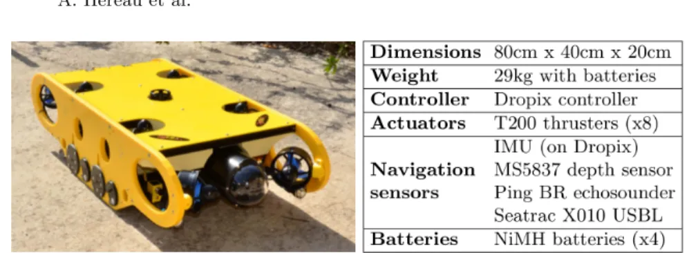
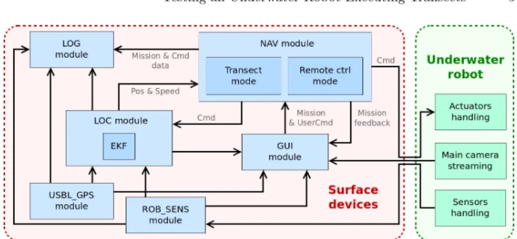
In this section, we describe our robotic system (Fig. 1) and its software archi-tecture (Fig. 2). The system under test includes two main parts: the surface devices, embedded on a boat, and the underwater robot4. The communication
between both parts is provided through a 200 meters ethernet cable with neu-tral buoyancy. Modbus protocol is used for sending command to the robot and receiving mission status.
With 4 vertical and 4 horizontal thrusters, the robot is a 6 degrees of freedom (DoF) semi-AUV which executes autonomously the classical transect mission under the supervision of an operator. As in most of hybrid-ROV or semi-AUV [2],
4
Fig. 1: Our 6DoF semi-AUV
the operator can launch, interrupt the current mission and take control of the robot in remote control mode. Our underwater robot named REMI embeds an IMU, an echosounder for altitude (i.e. distance between robot and seabed) and a pressure sensor for depth. Some sensors dedicated to safety help to supervise the robot such as water leak detector or intensity and voltage sensors in the powerswitchs. The main front camera sends real time video to the operator. Not considered in the system under test, two pairs of stereo cameras fixed afterward on the robot give the 3D visual information used by the biologists. One pair is oriented towards the front filming marine wildlife, the other facing down provides information about the seabed and fish habitats.
The surface devices include a user PC which displays the user interface to monitor the mission (GUI module) and allows to remotely control the robot. The user PC also processes the sensors connected to its serial ports: the GPS beacon receives its own georeferenced position and the USBL transducer calculates the 3D relative position of the robot thanks to an acoustic signal emitted by the transponder on the robot. By combining the GPS and USBL measurements in the USBL GPS module, the georeferenced position of the robot along the 3 dimensions of the NED frame (North-East-Down local frame) is calculated.
In this first prototype, we chose to implement the navigation and localization modules in the user PC for debugging ease. The ROB SENS module gets the sensors data provided by the embedded controller on the robot. LOG module records continually every mission, sensors, command or state time-stamped data in an output file. To minimize the process calculation time in the LOC module (localization module), we choose a simple EKF to get the robot estimated state
ˆ
X = [ν, η] with ν the robot velocity along the 6 DoF in the body-frame and η the robot position and quaternion attitude in the local NED frame. The EKF relies on the robot’s dynamic equations in the prediction part and merges the sensors data and the predicted state in the innovation part.
Our robot has two functioning modes : the remote control mode and the transect mode. Knowing the estimated state and the mission data in transect mode, the NAV module calculates the desired actuator propulsion in the body frame using a classic PID and sends it to the robot embedded controller which redistributes the command towards each thruster using the Moore–Penrose
in-Fig. 2: The navigation module in the software architecture
verse of the thruster configuration matrix. In remote control mode, the NAV module only transfers the command generated by the operator on the boat to the robot.
Having defined our system under test, we describe the test characteristics in the following section.
4
Test Design
The main objective of the tests is to validate that our robot can perform the transect mission. In this section, we present our methodology, we introduce our tests inputs and properties applied to the in-the-field test campaign of our robot prototype.
4.1 Our methodology
As said in section 2, we want to answer to the problematic of the validation testing in the field for underwater robots, introducing into the test method the consideration of the whole system and the constraints related to complex mis-sions. The system must be validated verifying a complete specification, i.e. a set of properties reflecting all the different constraints of the robot and its mission. For that, we adapt and extend the oracle test protocol developed in [11] used to validate a mobile agricultural robot, where properties are classified accord-ing to safety and mission perspectives. We also use the approach proposed in [8] to define several performance classes driven by a performance perspective: localization, energy, safety and time. We keep these 4 classes as well as the mis-sion phases breakdown of [11] to constitute our property classes. The time class imposes constraints over the duration of the mission phases. The safety class imposes constraints to preserve the robot integrity whereas the energy class im-poses constraints to make sure there is enough energy left. The localization class
imposes constraints on the precision of the localization. Finally, the mission phases class deals with the specifications of the user-oriented constraints over the whole mission.
During the oracle test, logged data are analyzed to verify if the properties are violated or not. In our case, the consideration of different mission phases (MPi) introduce a temporal constraint on the period of properties verification. We consider that there are 2 types of timing for a property verification : During one (or several) mission phases means that the property must be verified all along the concerned MPi; and At the end of a mission phase means that the property must only be verified at the end of the concerned phase. For a set of mission runs, we consider that the violation rate of a property is the number of times this property is violated out of the number of times the property is actually evaluated.
4.2 Test Case
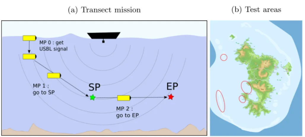
We choose to focus on the transect mission in autonomous mode. A transect is basically defined (Fig. 3a) by its Start Point (SP) and End Point (EP). We draw a virtual line between SP and EP called Transect Line (TL). A transect can be executed either at constant depth or constant altitude according to operator wishes. Thus in the latter case, TL becomes relative to altitude. The surge velocity fixed by the operator should not be too high to minimize the impact of the robot presence on submarine species.
We count 3 mission phases during the mission. As the USBL signal is not received when the robot is at surface, in the first mission phase 0 (MP0) the robot dives vertically until a certain depth to capture USBL signal from surface in order to be georeferenced. As soon as the robot receives the USBL signal, it switches to mission phase 1 (MP1) in which it navigates toward SP. Once SP is reached, mission phase 2 (MP2) consists in the core process of the transect: navigating horizontally toward EP along TL.
We decided to execute transect in different GPS localization around Mayotte to have different environment contexts (Fig. 3b). Swell was mainly present at the limit of coral reef sites (the 2 left zones on the map) and did not exceed 1m high. The distance between the surface and the seabed varied from 5m to 80m, the target transect depth varied between 2m and 40m and the target transect altitude between 1m and 5m. We varied the surge velocity from 0.5m/s to 1.0m/s for phase 1 and 0.1m/s to 0.4m/s for phase 2. We did not estimate more than 0.5m/s of sea current at surface. We performed test only during day-light in order to maximize the visibility of the front camera, even if water turbidity sometimes prevented it. The user boat was either anchored or could follow the underwater robot, especially in coral reef areas.
4.3 Oracle Properties
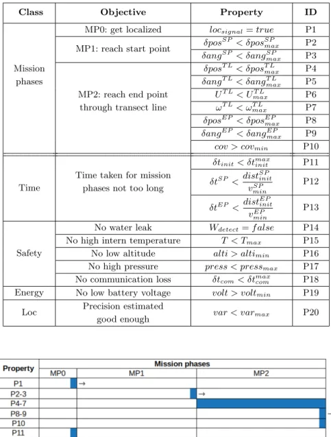
Table 1 shows the 20 properties we have defined following our classification method. Fig. 4 represents the property verification period.
(a) Transect mission (b) Test areas
Fig. 3: Test inputs: mission description and test areas
– Property P1 means that the georeferenced position of the robot must be known, i.e. the USBL and GPS signals must be received by the user PC. P1 must be verified at the end of MP0, and is a precondition to start MP1 (represented on Fig. 4 by the arrow on the right of the verification period). – P2 & P3: MP1 is finished if the position and attitude of the robot are close enough to SP with δposSP the distance between current position and SP ;
δangSP the absolute value of the angle between the desired attitude at SP
and the current attitude.
– P8 & P9: Likewise, MP2 is finished when the robot has reached EP. – P4 & P5: These properties check the distance to TL with δposT Lthe distance
between current position and its projection on TL and δangT Lthe difference
between the actual and desired angular positions of the robot. As shown on Fig. 4, these properties must be verified all along MP2.
– P6 & P7 : During MP2, we check the robot speeds with UT L=√u2+ v2+ w2
and ωT L =pp2+ q2+ r2 where (u, v, w, p, q, r) are respectively the surge,
sway, heave, roll, pitch, and yaw velocities of the robot.
– P10: At the end of MP2, the coverage rate of the estimated volume filmed by the robot divided by the desired volume must be above a threshold. The desired filmed volume is a 6x6m high and wide parallelepiped with TL as its main segment. The estimated filmed volume is a 6x6m square projected 4m in front of the robot and integrated on the estimated robot trajectory during MP2.
– P11: The robot must not takes more than δtmax
init time during initialization
– P12 & P13: For mission phases 1 and 2, we consider the distance to travel and we define minimum average speeds (vSPmin and vminEP) to calculate reference maximum times to reach SP and EP. The maximum time thresholds are equal to the initial distance to the targets (distSPinit and distEPinit) divided by the minimum average speeds to perform that motion.
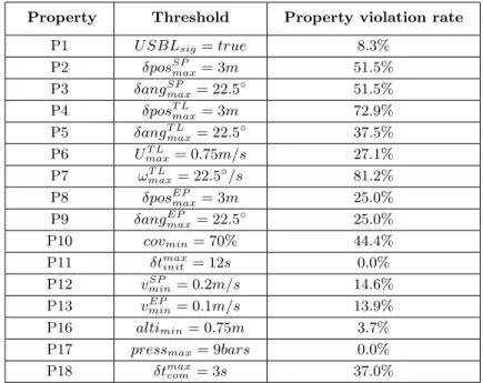
Table 1: Properties to verify
Class Objective Property ID
MP0: get localized locsignal= true P1
MP1: reach start point δpos
SP
< δposSPmax P2
δangSP < δangSPmax P3
Mission δposT L< δposT Lmax P4
phases δangT L< δangT Lmax P5
MP2: reach end point UT L< UmaxT L P6
through transect line ωT L< ωT L
max P7
δposEP < δposEP
max P8
δangEP < δangEP
max P9
cov > covmin P10
Time
δtinit< δtmaxinit P11
Time taken for mission
δtSP <dist SP init vSP min P12 phases not too long
δtEP <dist EP init vEP min P13 Safety
No water leak Wdetect= f alse P14
No high intern temperature T < Tmax P15
No low altitude alti > altimin P16
No high pressure press < pressmax P17
No communication loss δtcom< δtmaxcom P18
Energy No low battery voltage volt > voltmin P19
Loc Precision estimated var < varmax P20
good enough
– P15: We check that the intern temperature is not too high since it could indicate abnormal component behavior or fire start.
– P16: The altitude of the robot must remain above a threshold to prevent any collision with seabed.
– P17: The water pressure that must remain below a threshold to prevent any leaks of damage on components.
– P18: Communication between the user PC and the robot must not be inter-rupted too much time, especially with our deported control loop.
– P19: Energy axis is currently under study in LIRMM. For now, we only express one property as “having enough battery voltage”.
– P20 : Localization property class guarantees that the robot can localize itself in its environment. We check that each diagonal term of the estimated state covariance provided by the EKF is below a threshold.
Defining all these properties leads to a more systematic analysis of the test in order to find weaknesses in our design.
5
Experimental Results and Lesson Learned
In this section, we present and analyzed the results of the validation test cam-paign we performed in Mayotte early 2019. We logged 108 transects over 8 days on the field, at different localization around Mayotte as presented before. The log files generated contain the data to evaluate the oracle properties: the estimated state, the sensor measurements and the different events that occurred over time. The properties P14, P15, P19 and P20 are not evaluated since we lack log data to do so. This campaign was done to confront our first robot’s prototype with real in-the-field environment conditions. Table 2 shows the values of the property thresholds we fixed and the associated violation rate for all the transects. An important issue is the choice of the property threshold values, chosen accordingly to the biologist specifications and the physical constraints.
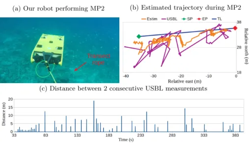
The first conclusion we made after this test campaign is that the current performances of our low cost sensors are not sufficient for the transect mission. The sensor uncertainties were prejudicial for the mission fulfillment as most of the properties were not respected. Indeed, the properties P4 & P10 in-volving the estimated position of the robot were often violated (resp. 72.9% and 44.4%). Some trajectory errors may come from the imperfection of the imper-fect servoing and the latency of the echosounder, but the main reason is the imprecision of the USBL sensor. To illustrate this issue, Fig. 5b represents the robot trajectory during MP2 of a transect. The real-time estimated trajectory (EKF) appears in orange, the USBL data in purple, and the transect line TL is plotted in blue between SP and EP. The USBL gave erratic values in these experiment conditions since it measured up to 19 meters difference between two consecutive measurements that were taken 10s apart with an estimated robot velocity of only 0.3m/s (Fig. 5c). In addition, we also noticed that the time to update measurement value varied between 2s and 25s for that transect. For per-forming precise underwater robotic missions, efficient and often costly sensors
Table 2: Property violation rates over all runs
Property Threshold Property violation rate
P1 U SBLsig= true 8.3% P2 δposSP max= 3m 51.5% P3 δangSPmax= 22.5 ◦ 51.5% P4 δposT L max= 3m 72.9% P5 δangT Lmax= 22.5 ◦ 37.5% P6 UT L max= 0.75m/s 27.1% P7 ωT Lmax= 22.5◦/s 81.2% P8 δposEP max= 3m 25.0% P9 δangEPmax= 22.5 ◦ 25.0% P10 covmin= 70% 44.4% P11 δtmaxinit = 12s 0.0% P12 vSP min= 0.2m/s 14.6% P13 vminEP = 0.1m/s 13.9% P16 altimin= 0.75m 3.7%
P17 pressmax= 9bars 0.0%
P18 δtmax
com = 3s 37.0%
are needed. However, a trend is also to deploy smaller and cheaper robots. A compromise is thus required and our approach using oracle properties may be useful to establish this compromise.
Getting the ground truth is complex for underwater experiments. As the properties are based on the robot state estimation, the problem is how to guarantee that this estimation is sufficiently closed to the reality, and this despite all the uncertainties? In order to verify the consistence of the localization data in our validation campaign, we materialized TL with a rope placed on the seabed (Fig. 5a). Looking at external videos, we checked the robot relative position on the rope and we compared it to the EKF estimation data. Even if this method is largely imprecise as it is based on a human evaluation, it was sufficient to detect some anomalies. This issue of ground truth is still an open issue [5], especially in underwater robotics where the logistics implementation of traditional solu-tions to obtain the ground truth (often environment instrumentation or used of accurate sensors) is difficult and very expensive.
The difficulty of building the oracle properties database is underes-timated. Defining an exhaustive and sufficient set of properties requires a high level of expertise particularly to determine the thresholds. Before the tests in Mayotte, we first defined an initial set of properties which is a subset of the one presented section 4.3. For example we initially did not consider the P7 property, and the system was not designed to stabilize precisely the angular velocity of the
(a) Our robot performing MP2 (b) Estimated trajectory during MP2
(c) Distance between 2 consecutive USBL measurements
Fig. 5: Localization error with USB
robot. But P7 shows a significant percentage of violations (81.2%), which proves that we must enhance our controller on that point. Another example is P18, with a violation rate of 37.0%. When violated, the robot is unable to reach SP and thus it prevents to respect all the properties related to MP1 and MP2. This fault was due to the presence of resettable fuse protecting the battery. The power cutting triggered a software failure of the communication protocol that remained persistent even after energy recovering. We did not planned this problem before as this fault was difficult to diagnose. Thus, experience in field experiments also played a key role to define a efficient set of properties to validate. The simple question “is the mission a success?” is not so simple to define. From the robot user’s point of view, achieving MP2 is the main objective. If we consider only the completion of MP2 (P8 & P9), and considering all the transects (including the ones where the MP0 and MP1 phases did not finished), the rate of mission success is 33.3% (failure rate of 66.7%). If we consider only the biologist initial specification defined by P10 for the video area verification, the rate of mission success is 18.5%. As this experiment was a first step in our development pro-cess, we did not investigate the formalization of such a mission success function. However, this would be an important tool, particularly to communicate with the biologists or even with certification bodies.
6
Conclusion
In this paper, we proposed a generic methodology to characterize tests with a mission point of view for the complete system. We identified several properties belonging to different property classes. Properties were associated with a period of verification: they could be check during or at the end of mission phases.
We applied this methodology on our semi-AUV prototype during a test cam-paign in the Mayotte lagoon. The analysis of these results first shows that our prototype must be improved since most of the oracle properties were not re-spected. This is globally not surprising as our robot is a first prototype and we use low-cost sensors. We plan to enhance both the hardware (with additional sensors) and software (with more efficient algorithm for example for data fu-sion) sides, and to carry out others test campaigns, enhancing again the oracle properties database and the test methodology.
We also plan to link our methodology of test with other dependability ap-proaches such as fault identification and diagnosis methods and fault trees to identify the different faults in real time. A real time property violation would then be the same as a fault detection in a fault tolerance approach, leading to basic recovery actions (stop of the mission, reboot) or more sophisticated ones at the decisional level.
References
1. Avizienis, A., et al.: Basic concepts and taxonomy of dependable and secure com-puting. IEEE Transactions on Dependable and Secure Computing pp. 11–33 (2004) 2. Bowen, A., et al.: The Nereus hybrid underwater robotic vehicle. Underwater
Tech-nology pp. 79–89 (2009)
3. Cinner, J.E., et al.: Bright spots among the world’s coral reefs. Nature pp. 416–419 (2016)
4. Dunbabin, M., et al.: Real-time Vision-only Perception for Robotic Coral Reef Monitoring and Management (2019)
5. Fallon, M.F., et al.: Cooperative AUV Navigation using a Single Maneuvering Sur-face Craft. The International Journal of Robotics Research pp. 1461–1474 (2010) 6. Hegrenaes, O., et al.: Validation of a new generation DVL for underwater
vehi-cle navigation. In: Autonomous Underwater Vehivehi-cles (AUV). pp. 342–348. IEEE, Tokyo, Japan (2016)
7. Jacoff, A., et al.: Development of standard test methods for evaluation of ROV/AUV performance for emergency response applications. In: OCEANS 2015. pp. 1–10. MTS/IEEE, Washington, DC (2015)
8. Lambert, P., et al.: An Approach for Fault Tolerant and Performance Guarantee Autonomous Robotic Mission. In: 2019 NASA/ESA Conference on Adaptive Hard-ware and Systems (AHS). pp. 87–94. IEEE, Colchester, United Kingdom (2019) 9. Lawrance, N.R., et al.: Ocean deployment and testing of a semi-autonomous
un-derwater vehicle. In: OCEANS. pp. 1–6. IEEE, Monterey, CA, USA (2016) 10. Ramesh, R., et al.: Development and Performance Validation of a Navigation
Sys-tem for an Underwater Vehicle. Journal of Navigation pp. 1097–1113 (2016) 11. Robert, C., et al.: The virtual lands of Oz: testing an agribot in simulation.
Em-pirical Software Engineering Journal (2020)
12. Sotiropoulos, T., et al.: Can Robot Navigation Bugs Be Found in Simulation? An Exploratory Study. In: International Conference on Software Quality, Reliability and Security (QRS). IEEE, Prague, Czech Republic (2017)
13. Williams, S., et al.: Monitoring of Benthic Reference Sites: Using an Autonomous Underwater Vehicle. IEEE Robotics & Automation Magazine pp. 73–84 (2012)