HAL Id: hal-01707513
https://hal.archives-ouvertes.fr/hal-01707513
Submitted on 12 Feb 2018
HAL is a multi-disciplinary open access
archive for the deposit and dissemination of
sci-entific research documents, whether they are
pub-lished or not. The documents may come from
teaching and research institutions in France or
abroad, or from public or private research centers.
L’archive ouverte pluridisciplinaire HAL, est
destinée au dépôt et à la diffusion de documents
scientifiques de niveau recherche, publiés ou non,
émanant des établissements d’enseignement et de
recherche français ou étrangers, des laboratoires
publics ou privés.
Modane: A Design Support Tool for Numerical
Simulation Codes
Benoît Lelandais, Marie-Pierre Oudot
To cite this version:
Benoît Lelandais, Marie-Pierre Oudot. Modane: A Design Support Tool for Numerical Simulation
Codes. Oil & Gas Science and Technology - Revue d’IFP Energies nouvelles, Institut Français du
Pétrole, 2016, 71 (4), pp.57. �10.2516/ogst/2016010�. �hal-01707513�
D o s s i e r
SimRace 2015: Numerical Methods and High Performance Computing for Industrial Fluid FlowsSimRace 2015 : Méthodes numériques et calcul haute performance pour la simulation d’écoulements complexes
Modane: A Design Support Tool for
Numerical Simulation Codes
Benoît Lelandais
*
and Marie-Pierre Oudot
CEA, DAM, DIF, Bruyères-le-Châtel, 91297 Arpajon – France e-mail: [email protected] - [email protected]
* Corresponding author
Abstract — The continual increasing power of supercomputers allows numerical simulation codes to take into account more complex physical phenomena. Therefore, physicists and mathematicians have to implement complex algorithms using cutting edge technologies and integrate them in large simulators. The CEA-DAM has been studying for several years the contribution of UML/MDE technologies in its simulators development cycle. The Modane application is one of the results of this work.
Résumé — Modane : un outil de conception pour les codes de simulation numérique — L’augmentation continuelle de la puissance des supercalculateurs permet la création de codes de simulation numérique de plus en plus aboutis. Par conséquent, les physiciens et mathématiciens en charge du développement sont confrontés à des algorithmes complexes qu’ils doivent intégrer dans de gros simulateurs en utilisant des technologies informatiques pointues. Le CEA-DAM étudie depuis plusieurs années l’apport des technologies UML/MDE au cycle de développement de ses simulateurs. Ce travail a notamment donné naissance à l’application Modane présentée dans cet article.
INTRODUCTION
The Modane application presented in this article in version 1.0, is a design support tool for numerical simulation codes based on Arcane. Arcane is a C++ development platform for 2D and 3D numerical simulation codes [1]. It aims at taking over the technical aspects of coding in order to accelerate the development of physical and numerical mod-ules, and also to ensure good performance of execution. Arcane was born in 2000 at CEA-DAM [2] and is co-developed with IFP Energies nouvelles [3] since 2007. It is proprietary software of these two companies.
Modane allows to graphically describe the static part of a numerical simulation code:
– components: variables, modules, services, structures, etc.
– relationships between components: implementation, inheritance and composition.
It also generates a portion of the source code of the future simulation software.
Modane does not tackle the algorithmic part of the code. Some tools like Archimede [4] include a graphical interface to specify algorithms. Others define a DSL (Domain Specific Language) for writing the body [5] of operations. Modane has no such ambitions and does not prevent developers using these tools. Its purpose is just to build the architecture of the application and explicitly define the couplings between the individual components that compose it.
Therefore, Modane does not directly address the problem of parallelism encountered in HPC (High Performance Com-puting) applications except for function supports (see the end of Sect. 2.4). However, the generated C++ code is
This is an Open Access article distributed under the terms of the Creative Commons Attribution License (http://creativecommons.org/licenses/by/4.0), which permits unrestricted use, distribution, and reproduction in any medium, provided the original work is properly cited.
dedicated to Arcane that supports parallel simulation codes. Also, by using Modane, we expect to increase simulators modularity to facilitate optimization by part.
This article presents the main objectives of Modane as well as functional and technical choices made to achieve them.
1. BACKGROUND AND OBJECTIVES 1.1. From Requirements to Source Code
Simulators achieved since 2000 highlight how complex the way from requirements to source code is. The engineers in charge of the development of numerical simulation codes have, for a majority of them, a background in mathematics. They can easily tackle the requirement process and capture, for instance, specifications in a Latex document. Then, they are faced with a significant amount of concepts and tech-nologies to design the physics module they have specified: the Object Oriented paradigm, the complexity of the C++ language, parallelism, etc. Consequently, the design process takes up too much time.
We ran several UML (Unified Modeling Language) analyzes [6], [7] to help the development of new physics modules. They did not significantly reduce the delay between the requirements and the source code but they demonstrated the interest to propose a graphical view of the design.
We so decided to build a tool to facilitate the development process by transforming graphical requirements into software components. It aims at reducing the time between the end of the requirements and thefirst lines of C++ source code. 1.2 Capture and Share“Business” Knowledge
In our current simulation codes, knowledge is shared between the specification document and the source code. Very few design documents describe the layout of key business concepts within the software. As time goes by, source code becomes the only real source of knowledge where it remains tricky tofind business information lost in C++ classes, going from basic types to main physics components.
Even if our simulators include documentations processed by Doxygen [8] as HTML reports, they don’t provide a “coarse grained” document, showing key business concepts that structure the application.
Modane aims at graphically shaping the architecture of the application around its key business concepts into a model that can be shared and exchanged to facilitate collaborative work.
1.3 Improve the Quality of the Design
In spite of the opportunities offered by Arcane, physics mod-ules remain monolithic and coupling problems yesterday encountered within codes appeared today inside modules. Consequently modules have to be regularly refactored. Their lifetime is between one and three years which is too short rel-ative to the business complexity, whose requirement process lasts several months.
A closer look at the code of our simulators reveals the fol-lowing design errors:
– developers do not create interfaces, and when they do, interfaces only remain a few months before becoming classes containing shared code because, in the C++ lan-guage, interfaces are implemented with classes;
– classes contain many lines of code. They grow up over time and exceed their scope because developers are reluc-tant to create new ones and to managefile inclusions; – there are too many couplings between classes. During the
design stage, “business” dependencies are created between components of the application. During the cod-ing stage, some relationships are added just for technical reasons creating unjustified links between components; – inheritance is misused. For an object-oriented technology
newcomer, inheritance appears as a miracle answer to share code. Over time, the inheritance tree becomes deep with overloading methods at several levels of depth. Modane aims at preventing these design errors.
1.4. Improve the Quality of the Source Code
To improve the homogeneity of the source code, Modane aims at offering a C++ code generator including design tem-plates and naming rules.
2. CHOSEN SOLUTION 2.1. Overview
To meet these objectives, Modane offers a GUI (Graphical User Interface) for capturing business knowledge and applies validation rules on the entered elements. It also pro-vides code generators allowing the developer to maintain the architecture of the simulator in accordance with the input knowledge entered in the GUI.
The graphical interface allows to:
– graphically create components coming from specifica-tions that will structure the software;
– navigate through the model and create graphical views; – apply a set of model validation rules and expose errors on
the model.
This interface and the generators are built on a model describing numerical simulation concepts identified by Arcane: variable, module, entry point, etc.
From a technology point of view, our business model is based on Eclipse EMF (Eclipse Modeling Framework) [9] and generators on Xtend [10]. These choices were led for the sake of homogeneity: these technologies are already used in other projects of our software stack. To get an integrated product, we should have created the GUI within Eclipse. Two solutions were studied in this respect: GMF (Graphical Modeling Framework) and GEF (Graphical Editor Framework) [11]. However, the estimated development cost was deemed too high tofinalize a first version of the tool. Besides, our development teams use Magicdraw UML modeler. This product supports the concept of profiles and provides customization options. Hence, rather than having a dedicated GUI, we decided to tune MagicDraw.
This solution implies creating a UML profile coming from our business model and developing validation rules using MagicDraw Java API. But benefits are numerous: It is fast to get afirst version of the interface, research tools on the model are powerful and presentation of error messages on the graphical view is convincing. The UML profile, graphic customization of the tool, definitions of dia-gram and validation rules are packaged in a module deployed in MagicDraw as a plug-in. The complete product has a very effective graphical interface, but the drawback is that models defined by users have to be exported from Mag-icdraw to Eclipse to trigger code generators and achieve C++ development.
The whole process can be summed up this way:
– graphically create a model within MagicDraw GUI thanks to the Modane plug-in. MagicDraw stores the project in a proprietary format;
– export the Magicdraw project in the UML2 EMF format; – generate and write the code inside Eclipse: models in EMF format are created during this process and are the knowledge base to generators.
To prevent switching from Magicdraw to Eclipse, one solution would have been to write code generators inside Magicdraw. However we decided to avoid using the legacy API or UML2 model API because we keep in mind the opportunity to offer an Eclipse integrated tool.
2.2. Business Model
Our business model is based on the main concepts of the Arcane platform [1]. It is the backbone of the application: the UML profile is based on these concepts, classes and functions used by code generators also.
The model is composed of mesh components such as cells, nodes or faces and basic types: integer, real, real vector
linked to the mesh sizes, tensor, etc. It also contains variables representing physical quantities, such as temperature or pressure.
Structures and enumerations have the same meaning as in programming languages.
Modules are the basic components of the simulator. They usually represent physics, such as hydrodynamic or thermic. They are made up of options and entry points. The options define the parameters of the module. The entry points are module’s operations which are visible from Arcane. The sequencing of modules operations can be configured within Arcane.
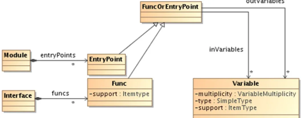
Interfaces have the same meaning as in programming languages. They contain a set of functions performed by the contract as defined by the interface. The functions have, of course, arguments and may be supported by a mesh element. It is for example possible to define a function for a cell (see the end ofSect. 2.4). Each entry point or function specifies the list of input and output variables (Fig. 1) and called functions.
Services can represent multiple implementations of the same interface. They implement the interface’s functions and they may include options just like modules.
Model elements are organized into packages.
The model was designed to avoid the design errors described in Section 2. The inheritance was limited on purpose: a structure can inherit another structure, an inter-face can inherit from another interinter-face. A service can imple-ment one interface. Regarding relationships, structures, modules, services and interfaces may have an association on a structure, an enumeration or interface (Fig. 2). 2.3. GUI and Checking Engine
The GUI allows to:
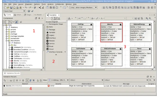
– create diagrams representing parts of the application (Fig. 3: Part 3). Only one type of diagram is required for this first release. This diagram includes a palette (Fig. 3: Part 2) to create objects defined in the model and relationships between these objects: association, inheritance, etc. Note that the user can create as many diagrams as he wishes;
– view the entire model tree form (Fig. 3: Part 1). Although diagrams show the components graphically, they only show a part of the objects;
– perform advanced searches on created objects: by name, type, use, dependence, etc.;
– trigger a model checker with custom set of rules. These rules produce different error levels (info, warning, error). Error messages are shown at the bottom of the screen (Fig. 3: Part 4). Elements holding an error are highlighted in red in the diagrams (Fig. 3: Part 3) and wear a red dot in the model tree (Fig. 3: Part 1).
Figure 4 shows an example of a diagram. Each of the rectangles represents a model object. The symbol in the top right of the rectangle and the background color are speci-fic to each object type. The diagram shows MicroHydro module, the BoundaryConditionType enumeration, BoundaryCondition structure, EquationOfState
interface and PerfectGas and StiffenedGas services.
This diagram also distinguishes two types of relations: – associations for options: MicroHydro has an
option named BoundaryCondition of type BoundaryConditionType;
Figure 2
Inheritance and associations. Figure 1
Functions and entry points.
– implementations of EquationOfState interface by PerfectGas and StiffenedGas services.
The diagram also presents the options and entry points of the MicroHydro module and the functions of the interface and its services.
It is possible to display, for each object, a specific prop-erty window. These windows have been customized in accordance with our UML profile (Fig. 5).
We previously saw that the model is designed to limit design errors. The graphical interface strives toward that goal:
– lack of interfaces: the component palette (Fig. 3: Part 2) facilitates the creation of interfaces. These interfaces will become fully generated and non-editable C++ classes in the source code (automatically regenerated and overwritten at each generation). Therefore they will
Figure 3 Main window.
Figure 4 Model example.
never host practical methods, often inserted there to share code;
– excessive class size: once again, the palette facilitates the creation of new components and so limits the size of classes. The model defines a role for each component that cannot easily be stepped out: for example, it is forbidden to send a module or service as argument;
– too many couplings: the model limits coupling construc-tions. Moreover, business relations are graphically highlighted (Fig. 4) to help developers to create associa-tions representing real“business” collaborations. Techni-cal couplings (mainly inheritances) are left to code generators.
Of course, users do not need to build their whole applica-tion with Modane. Some classes can directly be imple-mented in C++. Then, the quality of their design depends on the engineer’s experience. In this context, the code gen-erated by Modane can be used as a template.
2.4 Code Generators
The MagicDraw export option provides afile with the ‘uml’ extension. The user simply needs to select it in Eclipse brow-ser to trigger the generation using a contextual menu. Gener-ation options are set through a dialog box.
Modane will then:
– transform UML model into EMF model;
– apply some transformations on the EMF model: creation of default services, assignment of default values, etc.; – generate all modules and services descriptors, XML files
required by Arcane;
– generate interfaces, modules and services parent classes and data structures;
– generate skeleton classes for modules and services. These classes are dedicated to the developer who willfill them in
Figure 5
Entry point property window.
Figure 6
The generation process, example of a module.
with business algorithms. These classes are created only during the first code generation. They are never overwritten.
The C++ generator works like most GUI editors: final classes used by developers are created during thefirst gener-ation and they inherit from fully generated classes. Another solution would have been to regenerate all thefiles. In this case, developers would have been asked to fill in method bodies between tags marking the beginning and end of edi-table areas. However, most of them do not subscribe to this mechanism that makes them lose the ownership of theirfiles such as presentation or indentations.
Figure 6 shows an example of a user who defined a MicroHydro module in Modane. The generator will pro-vide the module descriptor MicroHydro.axl, the base class of the module MicroHydroModuleBase and the MicroHydroModule class with the skeletons of entry points defined in the model as hydroStartInit. The user has tofill in the body of the entry points.
To illustrate the contribution of the generation process on a function with a support, let’s take the example of a service containing a function f (. . .) with a Cell type support. The following items will be generated:
– in the service interface, an abstract method f(ConstCellVectorView items, etc.). This method allows the caller to provide the cell group to iterate; – in the base class, the actual method that implements that
interface. This method will loop over all group elements and trigger the process corresponding to a cell;
– in the base class, an abstract method f(const Cell cell, etc.). The developer will fill it in the subclass with the processing to be performed for a cell.
It is possible to mark the functions as“not parallel” in the model, such as when they contain interdependent iterations. For all other functions, generated loops use the Arcane ParallelForEach class to ensure multithread execu-tion.
As regards documentation, any element of the model can include a description which is sent out to the C++ source code as Doxygen comment. In addition, the generator uses
lists of variables and calls of functions to incorporate an interactive Dot graph as Doxygen comment (Fig. 7).
CONCLUSION
This article introduces the Modane software that helps to design numerical simulation codes based on the Arcane framework, describing its objectives, its architecture and its functionalities.
The development began in September 2011 and the soft-ware has been made available to users since April 2012. Since then, it has undergone variousfixes and improvements but no major changes. Since mid-2013, the business model is stable: changes mainly concern code generation.
Users acknowledge a real efficiency gain: Modane improves overview of the overall architecture of the simula-tor and a rapid integration of new collaborasimula-tors.
A review is currently underway to quantify the contribu-tions of Modane. It will determine the new features and pro-duct strategy to improve its usefulness.
REFERENCES
1 Grospellier G., Lelandais B. (2009) The Arcane development framework, POOSC‘09: Proceedings of the 8th workshop on Parallel/High-Performance Object-Oriented Scientic Comput-ing, Genova, Italy, 1-11.
2 CEA-DAM Available at: www-dam.cea.fr. 3 IFPEN Available at: www.ifpenergiesnouvelles.fr.
4 Lugato D. (2008) Model-driven engineering for high-perfor-mance computing applications, Proceedings of Modeling and Simulation Conference, Quebec City, Quebec, Canada, 1-8. 5 Di Pietro D., Gratien J.M., Häberlein F., Michel A.,
Prud'homme C. (2009) Basic concepts to design a dsl for par-allelfinite volume applications: extended abstract, POOSC '09: Proceedings of the 8th workshop on Parallel/High-Perfor-mance Object-Oriented Scientic Computing, Genova, Italy, 1-11.
6 Muller P.A. (1997) Modélisation objet avec UML, Eyrolles, Paris.
Figure 7
7 Booch G., Rumbaugh J., Jacobson I. (1999) The Unified Modeling Language User Guide, Addison Wesley, Boston. 8 Doxygen Available at: www.doxygen.org.
9 Moore B., Dean D., Gerber A., Wagenknecht G., Vanderheyden P. (2004) Eclipse development using the graphical editing framework and the eclipse modeling framework, IBM Red-books.
10 Xtend Available at: www.eclipse.org/xtend.
11 Steinberg D., Budinsky F., Paternostro M., Merks E. (2008) EMF Eclipse Modeling Framework, Addison Wesley, Boston.
Manuscript submitted in November 2015 Manuscript accepted in May 2016 Published online in August 2016
Cite this article as: B. Lelandais and M. Oudot (2016). Modane: A Design Support Tool for Numerical Simulation Codes, Oil Gas Sci. Technol71, 57.