HAL Id: hal-02366327
https://hal.archives-ouvertes.fr/hal-02366327
Submitted on 15 Nov 2019HAL is a multi-disciplinary open access archive for the deposit and dissemination of sci-entific research documents, whether they are pub-lished or not. The documents may come from teaching and research institutions in France or abroad, or from public or private research centers.
L’archive ouverte pluridisciplinaire HAL, est destinée au dépôt et à la diffusion de documents scientifiques de niveau recherche, publiés ou non, émanant des établissements d’enseignement et de recherche français ou étrangers, des laboratoires publics ou privés.
monolayer on Mn-doping configurations
I.C. Gerber, Adlen Smiri, Samir Lounis, Sihem Jaziri
To cite this version:
I.C. Gerber, Adlen Smiri, Samir Lounis, Sihem Jaziri. Dependence of the magnetic interactions in MoS 2 monolayer on Mn-doping configurations. Journal of Physics: Condensed Matter, IOP Publishing, 2019, 31 (46), pp.465802. �10.1088/1361-648X/ab360b�. �hal-02366327�
configurations
Adlen Smiri
Facult´e des Sciences de Bizerte, Laboratoire de Physique des Mat´eriaux: Structure et Propri´et´es, Universit´e de Carthage, 7021 Jarzouna, Tunisia and
LPCNO, Universit´e F´ed´erale de Toulouse Midi-Pyr´en´ees, INSA-CNRS-UPS, 135 Av. de Rangueil, 31077 Toulouse, France
Iann C. Gerber
LPCNO, Universit´e F´ed´erale de Toulouse Midi-Pyr´en´ees, INSA-CNRS-UPS, 135 Av. de Rangueil, 31077 Toulouse, France
Samir Lounis
Peter Gr¨unberg Institut and Institute for Advanced Simulation, Forschungszentrum J¨ulich and JARA, 52425 J¨ulich, Germany
Sihem Jaziri
Facult´e des Sciences de Bizerte, Laboratoire de Physique des Mat´eriaux: Structure et Propri´et´es, Universit´e de Carthage, 7021 Jarzouna, Tunisia and
Facult´e des Sciences de Tunis, Laboratoire de Physique de la Mati´ere Condens´ee, D´epartement de Physique, Universit´e Tunis el Manar, Campus Universitaire 2092 Tunis, Tunisia
Understanding the magnetic properties of the various Mn doping configurations that can be encountered in 2H-MoS2 monolayer could be beneficial for its use in spintronics. Using
density functional theory plus Hubbard term (DFT+U) approach, we study how a single iso-lated, double- and triple-substitution configurations of Mn atoms within a MoS2 monolayer
could contribute to its total magnetization. We find that the doping-configuration plays a critical role in stabilizing a ferromagnetic state in a Mn-doped MoS2monolayer. Indeed, the
Mn-Mn magnetic interaction is found to be ferromagnetic and strong for Mn in equidistant substitution positions where the separation average range of 6-11 ˚A. The strongest ferro-magnetic interaction is found when substitutions are in second NN Mo-sites of the armchair chain. Clustering is energetically favorable but it strongly reduces the ferromagnetic ex-change energies. Our results suggest that ordering the Mn dopants on MoS2 monolayer is
I. Introduction
On the grounds of their special structural and electronic properties [1–5], the two-dimensional transition metal (M) dichalcogenide (X) semiconductors (2D-TMDs) have shown peculiar optical characteristics [6–10] leading to several applications, such as optoelectronics [11, 12], including lasers and light-emitting diodes [13–16]. In the past few years, doping-induced magnetism in nonmagnetic 2D-TMDs, such as MoS2 [13, 17–24], WS2 [25], WSe2 [25] or SnS2 [26] systems has
deserved considerable attention. The magnetic properties of doped 2D-TMDs, such as strong ferromagnetism (FM) [17–22, 24, 26–28] and large magnetic anisotropy, are sought to be used in the ultimately small magnetic devices. To achieve this purpose, nonmetal (H, B, Cr, etc.) [24] and transition-metal (Mn, Fe, Nb, etc.) [13, 17–24] dopants through various doping strategies, such as substitution at M or X-sites [17–22, 25–28] and adsorption [23], have been used to tune magnetism in 2D-TMDs [17–23, 25–28].
Among 2D-TMDs, 2H-MoS2 monolayer (ML) has shown specific electronic transport
proper-ties, like considerable electron mobility (up to 1000 cm2/V s at low temperature) [29–32] or low power dissipation [31, 33, 34]. These features make this material a promising 2D-TMDs candidate for electronic transport devices, essentially for next-generation transistors [31, 33–35]. These trans-port abilities has led to extensive efforts to induce magnetism in MoS2 ML [13, 18–20, 22] in order
to control the electron spin and thus reach spintronic applications. To this end, one of the effective tools is to substitute some Mo atoms in ML by Manganese ones to produce Mn-doped MoS2, which
has attracted wide interest, either theoretically [18–20] or experimentally [13, 22]. Indeed, using first-principles calculations, it was demonstrated that this substitution is energetically favorable under S-rich regime, which is common in reaction medium for MoS2 nanosheets’ synthesis [19].
Moreover, substitutional Mn atoms was found to prefer clustering in MoS2 ML [21].
Experimen-tally, doped Mn-MoS2 sheets have been successfully synthesized through different methods. In
particular, Kehao et al. [6], succeeded to incorporate Mn in MoS2 ML via vapor phase deposition
techniques. More recently, a hydrothermal method for Mn-doped MoS2 ML synthesis has been
proposed by Jieqiong et al. [22].
According to several works [18, 20, 21, 27], the Mn impurities within MoS2 ML are coupled
ferromagnetically. In the earliest study of Mn-doped MoS2 ML, Ramasubramaniam and Naveh [20]
type of interaction is due to the presence of delocalized carriers between Mn impurities. However, the double-exchange mechanism was ruled out by Mishra et al. [18] based on the fact that there exists an antiferromagnetic (AFM) coupling between Mn atoms and their closest Sulfur atoms. More recently, another origin of magnetic interaction among Mn impurities in MoS2 ML has been
proposed and called successive spin polarizations (SSP) [37, 38]. The SSP magnetic coupling model is based on the spin-polarization induced by impurities in the host material to their nearest environment, i.e the closest atoms mainly [37–40]. In particular, a specific Mn impurity dictates the spin polarization of its first Next Nearest neighbors (NN), namely Mo and S, which in return dictate the spin polarization of the NN possible dopant [37, 38]. Unlike the double-exchange mechanism, the SSP FM coupling is based on localized electronic processes that take place be-tween Mn impurities [37]. Therefore, the SSP FM coupling can take place at low magnetic dopant concentrations which can be below the percolation threshold [37, 38]. Hence, a local enhancement of FM coupling by manipulating Mn-doping configurations may lead to avoid the need of high-doping concentration and still get strong ferromagnetism. Since the high-doping concentration cannot be easily controlled in experiments [22], the risk is high to lose the semi-conducting property of MoS2 ML at large dopant concentration [22]. To do this, one must first understand the role of
doping configurations in stabilizing the FM state of MoS2 ML.
In both studies of Ramasubramaniam and Naveh [20] and Mishra et al. [18], the FM coupling strength between two Mn impurities was found to decrease with respect to Mn-Mn distance’s increasing. Additionally, according to the SSP model, one can expect that the strength of the FM coupling can also depend drastically of the very local configuration between the two Mn atoms [37–40]. For instance, in the case of 1T0−MoS2 ML doped by substitution with Mn atoms, the strength of their magnetic interaction was found to be highly dependent on their relative positions [41]. Indeed, the FM coupling was found more pronounced when two Mn dopants were separated by 6.38 ˚A than by 3.81 ˚A [41]. Mind that similar conclusions have been drawn already in the case of FM coupling between Co atoms embedded in a single graphene sheet [42].
In Ref. [20] it was shown that the ferromagnetism in Mn-doped MoS2 ML becomes important
when the Mn-doping concentration increases. In particular, in 10-15% Mn-doping range, the Curie temperature was found to be above room temperature. Motivated by this result, Jieqiong et al. [22] succeeded to elaborate a MoS2 ML heavily doped with Mn impurities which gives rise
configurations contribute differently, and even not, to the overall ML’s ferromagnetism [22]. On the one hand, those Mn with NN forming Mn clusters are typically antiferromagnetic and thus do not contribute to the overall magnetization. On the other hand, only those Mn dopants that are at suitable distances can order ferromagnetically [22]. The diversity of magnetic behaviour of the different Mn doping configurations in MoS2 ML results on two different FM phases in this
material [22]. Therefore, distinguishing these different contributions is of high interest in order to potentially control magnetism in Mn-doped MoS2 ML.
Using Density Functional Theory plus Hubbard term (DFT+U), we perform a comprehensive investigation of structural stability and magnetic properties, namely magnetic exchange interaction and magnetic moments, of few near Mn-dopants embedded in MoS2 ML. By placing Mn atoms in
armchair- and/or zigzag-substitution Mo-sites with different Mn-Mn distances, we generate several doping configurations. Our aim is to explore the effect of these doping configurations on the magnetic coupling nature and strength among Mn impurities. To this end, the outline of this paper is as follows: we start by a description of our computational details and methods in section II. In section III we present and discuss our results for MoS2 ML with multiple Mn dopings: in
III. A, we validate our computational parameters and approachs by comparing our results of the isolated Mn-induced magnetic and electronic properties to that of literature. In III. B, we study the structural stability, pairwise exchange interaction of two Mn-dopants placed on armchair or zigzag chains as a function of Mn-Mn separations. In III. C, to broaden our understanding of the magnetic exchange interaction behavior versus the doping configurations, we add a third Mn-dopant. Indeed, by manipulating the three dopant positions, we are able to determine the effect of the doping clustering, doping shape (tiangle- or line- like) and equidistant or non-equidistant doping on the magnetic properties. We also discuss the dependence of the magnetic exchange interaction on inter-dopant distances. Our results are compared to previous calculations and to the experiment of Jieqiong et al. [22]. Finally, we conclude our results in section IV.
II. Methods and Computational details
Our work was based on spin-polarized DFT implemented in Vienna ab initio simulation package (VASP) [43, 44]. The exchange-correlation interaction was described using the Perdew-Burke-Ernzerhof (PBE) formulation of generalized gradient approximation (GGA) [45]. In addition, for 3d Mn orbitals, the Hubbard term correction (GGA+U) [46], was adopted. An on-site U
parameter of 5 eV, assigned to Mn impurity in Ref. [47], was considered. The core potential was approximated by the projected augmented wave (PAW) scheme [48]. A cutoff energy of 400 eV for the plane-wave basis set, was found sufficient to achieve a few meV convergence in energy in conjunction with a Brillouin zone sampling of 4×4×1 Gamma-centered Monkhorst-Pack grids. Finer grids (8×8×1) were used for density of states investigations. The criteria of atom force convergence, used for the structure relaxations, was fixed to 0.02 eV/˚A.
A distance of 20 ˚A between adjacent MoS2 MLs in perpendicular direction was considered to
eliminate spurious interactions resulting from the periodic boundary conditions. Three cases of Mn doping were adopted: an isolated Mn atom per supercell, two Mn atoms per supercell and three Mn atoms per supercell. In order to significantly reduce long range magnetic interaction between dopants in neighboring cells, a supercell of size 5×5×1 were used to contain one and two Mn dopants while for three Mn dopants, we have considered a 7×7×1 supercell.
The Mn impurities were placedin all nonequivalent positionsinside the supercells. The exchange interaction among them was evaluated by the exchange energy,
∆E = EFM− EAFM (1)
In fact, ∆E is the energy difference between the parallel and antiparallel impurity spin orientations. EFM and EAFM are the DFT total energies of self consistent calculations for the FM and AFM
configurations, respectively. The magnetic coupling nature (FM or AFM) and its strength was determined by the sign and amount of the exchange energy, respectively. It should be noted that our aim is to evaluate the exchange interaction through ∆E between a few dopants inside the supercell. A large negative ∆E indicates a large FM coupling with a relatively high Curie temperature [49, 50].
III. Results and discussion
A. Single Mn atoms in MoS2 monolayer
We begin our work by examining the electronic properties of an individual Mn dopant in a MoS2
ML at a doping concentration of 4%, see figure 1. In this case, Mn impurities are well separated by a distance equal to 16.25 ˚A. Therefore, one can assume that Mn impurities do not interact with
FIG. 1: A 4%-Mn atom doped ML is represented by 5 × 5 × 1 supercell, the yellow atoms are the Sulfur (S), the blue atoms are the Molybdenum (Mo) and the Manganese atom is denoted by
purple color.
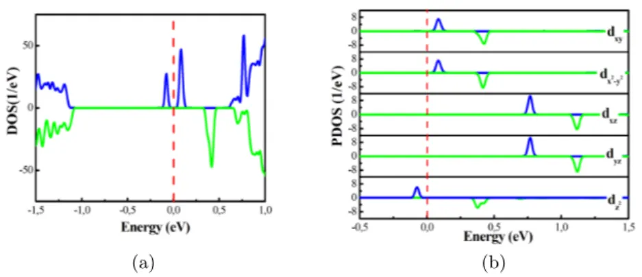
(a) (b)
FIG. 2. a) The spin-resolved total electron density of states (DOS) and b) the density of states projected on the d-states of Mn (PDOS) of Mn-doped MoS2. The blue and green lines denote the
spin-up and spin-down channels, respectively. The Fermi level is indicated by the red line.
each others.
The splitting of 3d orbital of Mn impurity in the MoS2ML are first investigated. The spin-resolved
total electron density of states (DOS) and the projected electron density of states (PDOS), are shown in 2a and 2b figures, respectively. As clearly seen in figure 2a, highly localized states occur in the band gap near the conduction band minimum. The origin of these states is the 3d Mn orbitals, figure 2b. The latter split into three groups the in-plane (dxy/x2−y2) orbitals, the
out-of-plane (dxz/yz) orbitals and the perpendicular dz2 orbital. The only occupied states are the spin
up dz2 orbital which gives rise to a total magnetic moment (MM) of 1µB. All these results are in
(a) -0.18 eV, 5.7 ˚A (b) -0.05 eV, 11.3 ˚A
(c) -0.14 eV, 3.5 ˚A (d) -0.15 eV, 6.5 ˚A
FIG. 3. Spin density isosurface distributions for 8%-Mn-doped MoS2 in 5×5×1 supercells. The
upper supercells contain each two Mn atoms in two armchair positions while the lower supercells contain each two Mn atoms in two zigzag positions. The energy differences between the AFM and FM coupling states (∆E) and Mn-Mn distances are listed for each configuration. The green
and red isosurfaces represent positive and negative spin density, respectively. The iso-surface value is 0.015 e˚A−3.
B. Double-substitution configurations of Mn atoms in MoS2 monolayer
In this section, two Mo atoms, from a 5×5×1 supercell, are replaced by two Mn atoms (noted Mn1 and Mn2 in figure 3), which represents 8% doping concentration in MoS2 ML. In this case,
the available substitution positions lead to four inequivalent configurations as plotted in figure 3. We have the following: (i) the configuration a (figure 3a), in which the Mn pairs are placed on 2nd NN positions of an armchair chain, with a Mn-Mn separation of 5.7 ˚A; (ii) the configuration b (figure 3b) in which, the Mn pairs are placed on 4nd NN positions of an armchair chain, with a Mn-Mn separation of 11.3 ˚A; (iii) the configuration c (figure 3c) in which the two Mn atoms are placed on two consecutive positions of a zigzag chain where the separation is equal to 3.5 ˚A; (iv) the configuration d (figure 3d) in which the Mn pairs are placed on 2nd NN substitution positions of a zigzag chain and separated by 6.5 ˚A.
TABLE I. Distance between impurities LMn1−Mn2(˚A), total MMs, local MMs (for Mn1 and Mn2)
and magnetic energies of various configurations which are shown in figure 3.
Double doping-configurations Separation distances Relative energy Total magnetic Local magnetic moment (µB) ∆E
LMn1−Mn2(˚A) (eV) moment (µB) Mn1 Mn2 (eV)
a 5.7 0.51 2.00 3.18 3.21 -0.18
b 11.3 0.51 1.99 3.19 3.21 -0.05
c 3.5 0.00 2.00 3.22 3.22 -0.14
d 6.5 0.40 2.00 3.20 3.20 -0.15
To get an idea about the stability of different configurations, their relative energies are listed in Table I. The lowest energy is corresponding to configuration c which contains the closest Mn impurities. This is followed by the configurations d, b and a. One can notice that the configurations with armchair position substitutions are less stable than those with zigzag position substitutions. Furthermore, we find that all double-doping configurations have a common total MM of ∼ 2µB.
This value is similar to that found by many previous reports [18–21].
In order to figure out the magnetic coupling nature in each doping configuration, their exchange energies are presented in table I. The exchange energy is found negative for the four configurations which means that they have stable FM states. In particular, for Mn-Mn separations equal or less than 5.7 ˚A, the double-doping configurations have large ∆E, above 0.10 eV, which should stabilize their FM nature at high temperature. The FM exchange interactions depend on the doping config-uration as well as Mn-Mn separations. More specifically, the configconfig-uration a shows the strongest FM exchange coupling even greater than configuration c which has the closest Mn pair. This domi-nance of the FM interaction between Mn impurities in the configuration a is also found in Ref. [21].
Using the SSP model, we investigate the magnetic coupling of two Mn dopants in different positions. To this end, the spin-polarized charge density isosurface distributions of the FM state for the different cases are shown the figure 3. According to the SSP model the Mn-Mn FM cou-pling is based on the interaction with the spin-polarized neighboring atoms, namely S and Mo atoms [37]. The Mn-Mn FM coupling is justified by the fact that the two dopants are identical and both induce the same type of polarization on nearby atoms [37]. For all doping configurations, the induced spins on the nearby host atoms are antiparallel to those of the Mn dopants. The same spin density behavior has been found in previous studies [18–21]. Furthermore, as shown in the table I, the local MMs of the dopants Mn are larger than the total MM of the doped ML. In fact, the AFM coupling between the impurities of Mn and their host NN atoms is at the origin of the
reduction of the total MM. The latter result is in agreement with Ref. [21].
As we mentioned before, the FM coupling depends on the strength of the induced polarization on the NN anions mediating the two dopants. Indeed, the strength of the induced antiparallel spin density that resides on the Mn-Mn mediating S and Mo, differs from one configuration to another, see figure 3. For the different configurations in figure 3, we classify the induced polariza-tion between Mn dopants from the strongest to the weakest as c than d, a and b configurations. For configuration b (figure 3b), the distance between two Mn dopants is 11.3 ˚A which is so large that the SSP processes between them is weak and therefore one can consider them to be almost isolated. For the rest of cases, we notice that the FM coupling is inversely proportional to the spin density magnitude that mediates the two Mn impurities. In particular, for the case of con-figuration c (figure 3c) there is a strong AFM coupling between Mn and the mediated S and Mo atoms, which weakens the FM interaction between the two dopants. For configuration d (figure 3d), Mn1 and the mediated host material atoms are less AFM coupled compared to configuration c. Thus, configuration d shows more stable Mn1-Mn2 FM coupling than c configuration. Unlike the latter two configurations c and d, a has the lowest AFM coupling between the dopants and the mediated atoms, which promotes its FM stability. It can be said that the antiparallel spin density in the middle of the dopants filters the FM interaction between the two dopants, more than it is important, more than the FM exchange is weak. In general, it can be said that the Mn-Mn mediating antiparallel spin density screens the FM interaction between the two dopants, more than it is important, more than the Mn-Mn FM exchange is weak.
C. Triple-substitution configurations of Mn atoms in MoS2 monolayer
In this section, we study the magnetic properties of three substitutional Mn impurities that replace three close Mo atoms of MoS2 ML. Unlike the previous section, we expand the supercell
to 7×7×1, which means a 6.12% doping concentration. A large number of configurations are con-sidered in which the Mn atoms are placed in various relative Mo-sites. In figure 4, we summarize the resulting triple-doping configurations (TDCs). In each case, for clarity, we show the relevant portion of the 7×7×1 supercell that contains the three dopants (figure 4).
(a) (b) (c) (d) (e) (f)
(g) (h) (i) (j) (k) (l)
FIG. 4: Schematics showing various configurations of triple-dopant configurations (TDCs) that were considered. Only the relevant portions of the 7×7×1 supercells are shown, for clarity. Blue, yellow, and purple balls represent Mo, S, and Mn atoms, respectively. In each case, the Mn atoms
are denoted by (1), (2) and (3). The energy differences between the FM state and the energetically-closest AFM state (∆E∗) are listed for each doping configuration.
calculations indicate that the configurations where the Mn impurities are placed at NN positions, namely configuration d, g and j, are more energetically favored compared to the rest of configura-tions. In other words, the three Mn dopants prefer to stay close to each other. In particular, the TDC lowest energy is associated to the configuration j, in which the impurities are bonded to the same S atom, see figure 4j. These results suggest that high concentration doping can lead to the clustering of Mn impurities in the MoS2 ML.
It should be noted also, as in table II, that while the NN TDCs, d g and j, have a large total MMs of ∼ 5 µB, the rest of configurations have a total MMs of just 3 µB. This difference of
total MM originates from the different environments of dopants. The total MMs result from the competition between the Mn positive local MMs and the negative local MMs of the host atoms. For instance, local spin magnetic moments of Mn impurities and their surrounding atoms for configurations a, j and h are depicted in figure 5. For the NN TDCs, local MMs of ∼ 10 µB and
(a) (b)
(c)
FIG. 5. The local spin magnetic moments in Bohr magneton of Mn impurities and of their surrounding neighboring atoms as obtained from the FM state for a) configuration a, b)
configuration j, and c) configuration h depicted in Fig. 4.
∼ -3.8 µB were found for the Mn impurities and the host atoms, respectively. However, for the
rest of configurations, local MMs of ∼ 9.7 µB and ∼ -5 µB were found for the Mn impurities and
the host atoms, respectively. The reduced MM of the environment of dopants in case of NN TDCs causes the increasing of their overall MMs.
The energy of the different considered magnetic states is denoted E(σ1, σ2, σ3), where σi
repre-sents the spin orientation of Mni impurities. Obviously, E(↑, ↑, ↑) is the energy of the FM state.
The enumeration of Mni is shown in figure 4 for all TDCs. For the sake of comparison, we denote
FIG. 6: a) The gain in energy of the FM ordering over AFM ordering of spins for the three Mn impurities as a function of the average separation distance, < L >, between the impurities. the
negative (positive) energy corresponds to FM (AFM) ordering being more stable.
In Table II, we present the energy differences, ∆E, between FM and non-FM configurations for the various TDCs. In each TDC, the energy difference between the ground state and the energetically-closest magnetic state is asterisked ∆E∗ in table II. The FM state is found to be stable for all TDCs except configuration e which has an AFM ground state. Furthermore, for each TDC the energy differences, ∆E, where the AFM energies have the spin configurations (↓, ↑, ↑) or (↑, ↓, ↑), arelargest. This result proves that the NN impurities, Mn1 and Mn2 as shown in figure 4,
have a strong FM coupling. However, the presence of a third close Mn impurity tends in general to destabilise the FM state. For configuration e, the ground state becomes even AFM (↑, ↑, ↓). Clearly, modifying the doping configurations alters the stability of the FM state and with that certainly the strength and nature of the inter-impurities magnetic interactions.
In particular, depending on the FM stability and the geometric similarities, three TDC groups stand out. (i) The first TDC group is formed by configurations a, f, i, and l. Here, in each config-uration, at least one Mn dopant is placed at the mediator of the segment formed by the other two Mn dopants. At least two pairs of Mn atoms are 2nd NNs, see figures 4a, 4f, 4i, 4l. The TDCs in this group have the most stable FM states compared to the rest of configurations. Indeed, ∆E∗ are of the order of hundreds meV which is comparable to the a, c, and d double-doping configuration energies. Similar to the case of double-doping configurations, Mn dopants on the 2nd NN positions of an armchair chain, configuration a, exhibits the most stable FM-state. Ordering the Mn dopants
TABLE II. Relative energies, total magnetic moments (MMs) and the energy differences between FM and non-FM spin configurations, ∆E, of various triple doping configurations. The asterisk
indicates the energetically closest spin configuration to the ground state.
Configurations Relative energy (eV) MM(µB) Spin configurations ∆E (eV)
a 2.11 2.99 E(↑, ↑, ↑) − E(↑, ↓, ↑) -0.24 E(↑, ↑, ↑) − E(↑, ↑, ↓)∗ -0.14 b 2.10 2.99 E(↑, ↑, ↑) − E(↑, ↓, ↑) -0.13 E(↑, ↑, ↑) − E(↓, ↑, ↑) -0.12 E(↑, ↑, ↑) − E(↑, ↑, ↓)∗ -0.02 c 2.26 2.99 E(↑, ↑, ↑) − E(↓, ↑, ↑) -0.04 E(↑, ↑, ↑) − E(↑, ↓, ↑)∗ -0.02 d 0.71 5.00 E(↑, ↑, ↑) − E(↑, ↓, ↑) -0.14 E(↑, ↑, ↑) − E(↑, ↑, ↓)∗ -0.07 e 2.45 1.00 E(↑, ↑, ↑) − E(↑, ↓, ↑) -0.07 E(↑, ↑, ↑) − E(↑, ↓, ↑) -0.07 E(↑, ↑, ↑) − E(↑, ↑, ↓)∗ 0.01 f 1.88 2.99 E(↑, ↑, ↑) − E(↑, ↓, ↑) -0.25 E(↑, ↑, ↑) − E(↑, ↑, ↓)∗ -0.11 g 0.45 4.97 E(↑, ↑, ↑) − E(↑, ↓, ↑)∗ -0.05 h 1.30 3.00 E(↑, ↑, ↑) − E(↑, ↓, ↑) -0.14 E(↑, ↑, ↑) − E(↓, ↑, ↑) -0.09 E(↑, ↑, ↑) − E(↑, ↑, ↓)∗ -0.00 i 2.90 3.00 E(↑, ↑, ↑) − E(↑, ↓, ↑) -0.22 E(↑, ↑, ↑) − E(↑, ↑, ↓)∗ -0.10 j 0.00 5.00 E(↑, ↑, ↑) − E(↑, ↓, ↑)∗ -0.01 k 1.34 4.99 E(↑, ↑, ↑) − E(↑, ↓, ↑) -0.10 E(↑, ↑, ↑) − E(↓, ↑, ↑) -0.11 E(↑, ↑, ↑) − E(↑, ↑, ↓)∗ -0.03 l 1.83 3.00 E(↑, ↑, ↑) − E(↑, ↑, ↓)∗ -0.12
on the MoS2 ML in this particular set of configurations can increase the temperature stability of
the FM state. (ii) The second group includes configurations d, g and j. In contrast to the first group, here the Mn atoms are placed in the NN positions (see figures 4d, 4g, 4j). In this case, the FM interaction of the TDC is weak since ∆E∗ is of the order of tens meV. In this group, the lowest ∆E∗ is found for configuration j. The origin of the reduction of the overall FM state of configuration j is attributed to the strong AFM coupling of the three dopants with the mediating atoms, see figure 5b. Therefore, clustering of Mn impurities in the ML is not preferable if we want to get strong ferromagnetism. This means that although clustering is energetically favorable, we need to avoid it. This result is consistent with an observation of Jieqiong et al. [22] in which those Mn with NN form Mn clusters are typically AFM. (iii) A weak FM interaction is also found in the third group which includes the configurations b, e, h, and k. Here, the three dopants are placed at different distances from each others (see figures 4b, 4e, 4h, 4k). In other words, one Mn dopant is far from the other two Mn which are close to each other. As shown in figure 5c for configuration h, a strong negative local MM of ∼ −0.4 µB resides on the mediating Mo between the two close Mn
and the far Mn dopant. This explains why the third far Mn reduces the FM state of configuration i. In Ref. [38], according to SSP, if one dopes with two different magnetic impurities, the spin polarization on the mediating host atom will take the characteristics of the strongest polarization induced on it by the two neighboring impurities. In our case, the situation is quite similar, the two close Mn atoms act as one atom that induces a strong AFM polarization on the host atoms which dictates the spin polarization of the third Mn atom. This favors the tendency towards a weak FM coupling or even for an AFM coupling, as obtained for configuration e, between the two close Mn impurities and the far Mn impurity.
To get a better insight on the ferromagnetic stability of the TDCs, we plot in 6, ∆E∗ as a function of the average separation distances between the impurities. One notices that the most stable FM state is realized for the average separation distance ranging from 6 to 9 ˚A. Outside these inter-impurity distances, the FM state is weakened but maintained up to large distances. Our findings are in agreement with the experiment reported in Ref. [22], which indicates that only Mn impurities that are at suitable distances can order ferromagnetically. Figure 6 shows furthermore that the doping configuration plays a criticial role in the magnetic stability of the impurities com-plexes since for comparable averaged inter-impurity distances the energy differences can be very different. For instance, ∆E∗for configuration j (-0.01 eV) is about 5 times smaller than that of con-figuration g (-0.05 eV) although they are both characterized by the same averaged Mn-Mn distance.
After our discussion of the magnetic stability of the various complexes, we complete our study by evaluating the magnetic interactions among the Mn atoms. To this end, we map the energy differences obtained from first-principles for the various studied magnetic states to those of the classical Heiseberg model, H = −12P
i6=jJijeiej. Here ei is the unit
vec-tor defining the direction of Mn atomic MM at site i and Jij are the magnetic exchange
coupling constants between the local moments at Mn-sites i and j. For the double-doping configuration, J12double = −∆E
2 . For the triple-doping configurations, we have different cases. When Mn-complex form an equilateral triangle, the three possible AFM states are degener-ate, i.e. (↓, ↑, ↑) ≡ (↑, ↓, ↑) ≡ (↑, ↑, ↓) and J12triple = J23triple = J13triple = −∆E
4 . In the case of two inequivalent AFM states, J12triple = J23triple = −∆E1
4 and J
triple
13 =
∆E1− 2∆E2
4 where
∆E1 = E(↑, ↑, ↑) − E(↑, ↓, ↑) and ∆E2 = E(↑, ↑, ↑) − E(↑, ↑, ↓). Finally, when the three
AFM states are inequivalent, J12triple = −∆E1− ∆E2+ ∆E3
4 , J
triple
23 =
∆E1− ∆E2− ∆E3
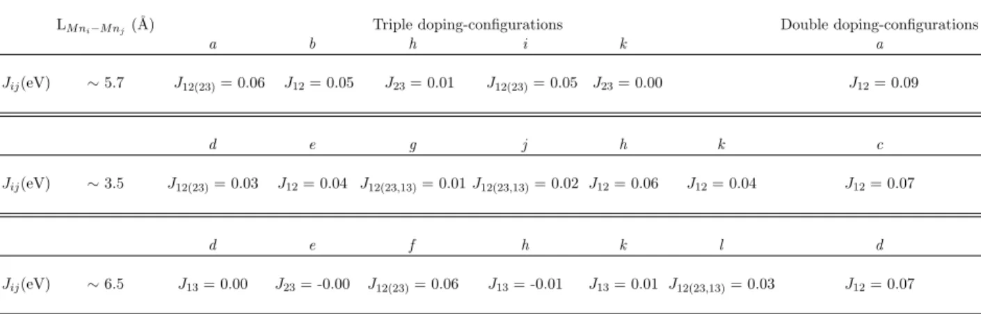
TABLE III. Estimated magnetic exchange coupling constants Jij of triple- and double-doping
configurations. Each Jij row corresponds to the Mn-pairs with common separation distance
LM ni−M nj.
LM ni−M nj(˚A) Triple doping-configurations Double doping-configurations
a b h i k a Jij(eV) ∼ 5.7 J12(23)= 0.06 J12= 0.05 J23= 0.01 J12(23)= 0.05 J23= 0.00 J12= 0.09 d e g j h k c Jij(eV) ∼ 3.5 J12(23)= 0.03 J12= 0.04 J12(23,13)= 0.01 J12(23,13)= 0.02 J12= 0.06 J12= 0.04 J12= 0.07 d e f h k l d Jij(eV) ∼ 6.5 J13= 0.00 J23= -0.00 J12(23)= 0.06 J13= -0.01 J13= 0.01 J12(23,13)= 0.03 J12= 0.07
J13triple= −∆E1+ ∆E2− ∆E3
4 where ∆E3= E(↑, ↑, ↑) − E(↓, ↑, ↑).
The estimated values of Jij are listed in table III. Comparing the constants Jijtriple to Jijdouble, we
see that some of them remain almost unaltered and some others change significantly. For instance, the first Jij line in table III shows that except for the doping configurations h and k, the exchange
coupling constants Jijdouble of Mn pairs placed on the 2nd NN Mo-site, are comparable to Jijdouble. Furthermore, for the other two lines, it is clear that there is a large fluctuation of Jijtriplewith respect
to Jijdouble. This reveals the dependence of pairwise magnetic coupling on the pair environment
which contains a third dopant as expected from our previous discussion. Interestingly, we note one case where the magnetic interaction becomes AFM: configuration h while for configurations d, k and e the magnetic interactions between the furthest apart Mn atoms is negligible.
IV. Conclusion
Performing DFT+U calculations, we show that the magnetic stability and the magnetic ex-change interaction between neighboring dopants are very sensitive to the doping-configuration geometry and the dopant separation distances. Our calculations suggest on the one hand that placing Mn dopants at equidistant Mo-sites where the average dopants separation is 6-9 ˚A, en-hances the ferromagnetism of Mn-doped MoS2 ML. The Mn impurities that are placed on the
FM exchange interaction is found to be reduced dramatically when we have a Mn impurity close to a Mn-cluster. Interestingly, the ferromagnetic interactions are in general finite for large inter-impurity distances. In addition, the Mn impurities in the closest Mo-sites, clusters, show weak FM coupling. The diversity in the FM coupling strength for the various doping configuration is due to the strength of antiparallel spin polarized Mo and S atoms that are mediating the interactions among Mn impurities. When the Mn impurities approach each other the anti-parallel mediating MMs increase, which reduces the FM exchange interaction. It should be noted that, the doping configuration in which the FM exchange is low are found energetically favorable indicating that Mn impurities have the tendency to clustering within the MoS2 ML. Our results show that doping
control is very necessary to take advantage of magnetic properties of this material. This is achiev-able with atomic manipulation using scanning tunneling microscopy, which in its spin-polarized version allows even to extract magnetic exchange interactions at the atomic scale [51, 52]. This offers the possibility of confirming our predictions.
ACKNOWLEDGMENT
I.C.G. thanks the CALMIP initiative for the generous allocation of computational time through project p0812, as well as GENCI-CINES and GENCI-IDRIS for Grant No. 2018-A004096649. S.L. acknowledges funding from the European Research Council (ERC) under the European Unions Horizon 2020 research and innovation programme (ERC-consolidator Grant No. 681405 DYNA-SORE).
[1] S. Najmaei, Z. Liu, W. Zhou, X. Zou, G. Shi, S. Lei, B. I. Yakobson, J.-C. Idrobo, P. M. Ajayan, and J. Lou, Nature materials 12, 754 (2013).
[2] C. Tan and H. Zhang, Chem. Soc. Rev. 44, 2713 (2015).
[3] B. Li, L. Huang, M. Zhong, Y. Li, Y. Wang, J. Li, and Z. Wei, Advanced Electronic Materials 2, 1600298 (2016).
[4] G.-B. Liu, W.-Y. Shan, Y. Yao, W. Yao, and D. Xiao, Phys. Rev. B 88, 085433 (2013). [5] S. Leb`egue and O. Eriksson, Phys. Rev. B 79, 115409 (2009).
[6] B. Zhu, X. Chen, and X. Cui, Scientific reports 5, 9218 (2015).
[7] D. W. Kidd, D. K. Zhang, and K. Varga, Physical Review B 93, 125423 (2016). [8] I. Kyl¨anp¨a¨a and H.-P. Komsa, Physical Review B 92, 205418 (2015).
[9] A. Raja, A. Chaves, J. Yu, G. Arefe, H. M. Hill, A. F. Rigosi, T. C. Berkelbach, P. Nagler, C. Sch¨uller, T. Korn, et al., Nature communications 8, 15251 (2017).
[10] A. V. Stier, N. P. Wilson, G. Clark, X. Xu, and S. A. Crooker, Nano letters 16, 7054 (2016).
[11] Q. H. Wang, K. Kalantar-Zadeh, A. Kis, J. N. Coleman, and M. S. Strano, Nature nanotechnology 7, 699 (2012).
[12] M. S. Choi, D. Qu, D. Lee, X. Liu, K. Watanabe, T. Taniguchi, and W. J. Yoo, ACS nano 8, 9332 (2014).
[13] K. Zhang, S. Feng, J. Wang, A. Azcatl, N. Lu, R. Addou, N. Wang, C. Zhou, J. Lerach, V. Bojan, et al., Nano letters 15, 6586 (2015).
[14] R. Sundaram, M. Engel, A. Lombardo, R. Krupke, A. Ferrari, P. Avouris, and M. Steiner, Nano letters 13, 1416 (2013).
[15] Y. Ye, Z. Ye, M. Gharghi, H. Zhu, M. Zhao, Y. Wang, X. Yin, and X. Zhang, Applied Physics Letters 104, 193508 (2014).
[16] Y. Ye, Z. J. Wong, X. Lu, X. Ni, H. Zhu, X. Chen, Y. Wang, and X. Zhang, Nature Photonics 9, 733 (2015).
[17] Y. C. Cheng, Z. Y. Zhu, W. B. Mi, Z. B. Guo, and U. Schwingenschl¨ogl, Phys. Rev. B 87, 100401 (2013).
[18] R. Mishra, W. Zhou, S. J. Pennycook, S. T. Pantelides, and J.-C. Idrobo, Phys. Rev. B 88, 144409 (2013).
[19] Q. Fang, X. Zhao, Y. Huang, K. Xu, T. Min, P. K. Chu, and F. Ma, Phys. Chem. Chem. Phys. 20, 553 (2018).
[20] A. Ramasubramaniam and D. Naveh, Phys. Rev. B 87, 195201 (2013).
[21] X.-L. Fan, Y.-R. An, and W.-J. Guo, Nanoscale Research Letters 11, 154 (2016), ISSN 1556-276X. [22] J. Wang, F. Sun, S. Yang, Y. Li, C. Zhao, M. Xu, Y. Zhang, and H. Zeng, Applied Physics Letters
109, 092401 (2016).
[23] W. Cong, Z. Tang, X. Zhao, and J. Chu, Scientific reports 5, 9361 (2015). [24] Q. Yue, S. Chang, S. Qin, and J. Li, Physics Letters A 377, 1362 (2013).
[25] Y.-X. Song, W.-Y. Tong, Y.-H. Shen, S.-J. Gong, Z. Tang, and C.-G. Duan, Journal of Physics: Condensed Matter 29, 475803 (2017).
[26] L. Sun, W. Zhou, Y. Liang, L. Liu, and P. Wu, Computational Materials Science 117, 489 (2016). [27] J. Gao, Y. D. Kim, L. Liang, J. C. Idrobo, P. Chow, J. Tan, B. Li, L. Li, B. G. Sumpter, T.-M. Lu,
et al., Advanced Materials 28, 9735 (2016).
[28] L. Seixas, A. Carvalho, and A. C. Neto, Physical Review B 91, 155138 (2015).
[29] Y. Cai, G. Zhang, and Y.-W. Zhang, Journal of the American Chemical Society 136, 6269 (2014). [30] B. W. Baugher, H. O. Churchill, Y. Yang, and P. Jarillo-Herrero, Nano letters 13, 4212 (2013). [31] D. Lembke and A. Kis, ACS nano 6, 10070 (2012).
[32] H. Schmidt, S. Wang, L. Chu, M. Toh, R. Kumar, W. Zhao, A. Castro Neto, J. Martin, S. Adam, B. Ozyilmaz, et al., Nano letters 14, 1909 (2014).
[33] B. Radisavljevic, M. B. Whitwick, and A. Kis, ACS nano 5, 9934 (2011). [34] Y. Zhang, J. Ye, Y. Matsuhashi, and Y. Iwasa, Nano letters 12, 1136 (2012).
[35] J. Lin, J. Zhong, S. Zhong, H. Li, H. Zhang, and W. Chen, Applied Physics Letters 103, 063109 (2013). [36] K. Sato, L. Bergqvist, J. Kudrnovsk`y, P. H. Dederichs, O. Eriksson, I. Turek, B. Sanyal, G. Bouzerar,
H. Katayama-Yoshida, V. Dinh, et al., Reviews of modern physics 82, 1633 (2010). [37] A. N. Andriotis and M. Menon, Physical Review B 90, 125304 (2014).
[38] A. N. Andriotis, Z. G. Fthenakis, and M. Menon, Journal of Physics: Condensed Matter 27, 052202 (2015).
[39] A. N. Andriotis and M. Menon, Journal of Physics: Condensed Matter 24, 455801 (2012). [40] A. N. Andriotis and M. Menon, Physical Review B 87, 155309 (2013).
[41] X. Lin and J. Ni, Journal of Applied Physics 120, 064305 (2016).
[42] S. Lisenkov, A. N. Andriotis, and M. Menon, Physical review letters 108, 187208 (2012). [43] G. Kresse and J. Hafner, Phys. Rev. B 47, 558 (1993).
[44] G. Kresse and J. Hafner, Phys. Rev. B 49, 14251 (1994).
[45] J. P. Perdew, K. Burke, and M. Ernzerhof, Phys. Rev. Lett. 77, 3865 (1996).
[46] S. L. Dudarev, G. A. Botton, S. Y. Savrasov, C. J. Humphreys, and A. P. Sutton, Phys. Rev. B 57, 1505 (1998).
[47] Y. Wang, L.-T. Tseng, P. P. Murmu, N. Bao, J. Kennedy, M. Ionesc, J. Ding, K. Suzuki, S. Li, and J. Yi, Materials & Design 121, 77 (2017).
[48] P. E. Bl¨ochl, Phys. Rev. B 50, 17953 (1994).
[49] J. Kudrnovsk´y, I. Turek, V. Drchal, F. M´aca, P. Weinberger, and P. Bruno, Phys. Rev. B 69, 115208 (2004).
[50] M. Kan, J. Zhou, Q. Sun, Y. Kawazoe, and P. Jena, The journal of physical chemistry letters 4, 3382 (2013).
[51] L. Zhou, J. Wiebe, S. Lounis, E. Vedmedenko, F. Meier, S. Bl¨ugel, P. H. Dederichs, and R. Wiesen-danger, Nature Physics 6, 187 (2010).