HAL Id: hal-02929876
https://hal.archives-ouvertes.fr/hal-02929876
Submitted on 3 Sep 2020
HAL is a multi-disciplinary open access
archive for the deposit and dissemination of
sci-entific research documents, whether they are
pub-lished or not. The documents may come from
teaching and research institutions in France or
abroad, or from public or private research centers.
L’archive ouverte pluridisciplinaire HAL, est
destinée au dépôt et à la diffusion de documents
scientifiques de niveau recherche, publiés ou non,
émanant des établissements d’enseignement et de
recherche français ou étrangers, des laboratoires
publics ou privés.
Mobility of <c +a> dislocations in zirconium
Thomas Soyez, Daniel Caillard, Fabien Onimus, Emmanuel Clouet
To cite this version:
Thomas Soyez, Daniel Caillard, Fabien Onimus, Emmanuel Clouet. Mobility of <c +a> dislocations
in zirconium. Acta Materialia, Elsevier, 2020, 197, pp.97-107. �10.1016/j.actamat.2020.07.026�.
�hal-02929876�
Mobility of hc + ai dislocations in zirconium
Thomas Soyeza, Daniel Caillardb, Fabien Onimusc, Emmanuel Cloueta,∗aUniversit´e Paris-Saclay, CEA, Service de Recherches de M´etallurgie Physique, F-91191 Gif-sur-Yvette, France bCEMES-CNRS, 29 rue Jeanne Marvig, BP 94347, F-31055 Toulouse, France
cUniversit´e Paris-Saclay, CEA, Service de Recherches M´etallurgiques Appliqu´ees, F-91191 Gif-sur-Yvette, France
Abstract
Plasticity in hexagonal close-packed zirconium is mainly controlled by the glide of dislocations with 1/3 h1210i Burgers vectors. As these dislocations cannot accommodate deformation in the [0001] direc-tion, twinning or glide of hc + ai dislocations, i.e. dislocations with 1/3 h1213i Burgers vector, have to be activated. We have performed in situ straining experiments in a transmission electron microscope to study the glide of hc + ai dislocations in two different zirconium samples, pure zirconium and Zircaloy-4, at room temperature. These experiments show that hc + ai dislocations exclusively glide in first-order pyramidal planes with cross-slip being activated. A much stronger lattice friction is opposing the glide of hc + ai dislo-cations when their orientation corresponds to the hai direction defined by the intersection of their glide plane with the basal plane. This results in long dislocations straightened along hai which glide either viscously or jerkily. This hai direction governs the motion of segments with other orientations, whose shape is merely driven by the minimization of the line tension. The friction due to solute atoms is also discussed.
Keywords: Dislocations, Plasticity, Zirconium, In situ straining experiments, Transmission electron microscopy
1. Introduction
Zirconium alloys are used in the nuclear indus-try as fuel cladding tubes and structural compo-nents in light and heavy water reactors [1]. Like in other hexagonal close-packed (hcp) metals, plastic activity strongly varies between the different pos-sible slip systems in zirconium. The principal slip system is controlled by glide of hai dislocations, i.e. dislocations with 1/3 h1210i Burgers vectors, in the {1010} prismatic planes [2, 3]. These hai disloca-tions can also cross-slip above room temperatures to glide in the (0001) basal and {1011} first-order pyramidal planes [4]. However all these deforma-tion modes only accommodate deformadeforma-tion along hai directions and other mechanisms, either twin-ning or glide of dislocations with a hci component, are needed to allow for a deformation along the hci = [0001] axis of the hcp crystal.
∗Corresponding author
Email address: [email protected] (Emmanuel Clouet)
Both twinning and glide of hc + ai dislocations, i.e. dislocations with 1/3 h1123i Burgers vectors, are active in zirconium [5–15], with hc + ai slip becoming more active when the temperature in-creases. Depending of the hcp metals, these hc + ai dislocations can glide in the first-order {1011} or second-order {2112} pyramidal planes. Almost all transmission electron microscopy (TEM) observa-tions have shown, by slip traces analysis [7] or stereography [8, 10, 11, 13–16], that hc + ai dis-locations glide in first-order pyramidal planes in Zr alloys, with possible cross-slip between two pyrami-dal planes sharing the same hc + ai direction [14– 16]. Scanning electron microscopy of slip traces on bended micro-cantilever well oriented to activate only hc + ai slip also concluded that hc + ai disloca-tion glide in first-order pyramidal planes, without any trace of slip in second-order pyramidal planes, both for the compressive and tensile parts of the cantilevers [17]. Only Long et al. [16] have recently evidenced that a minority of hc + ai can also be found in the second order pyramidal plane in a Zr-2.5Nb alloy. Besides, some of these TEM
observa-tions indicate that hc + ai dislocaobserva-tions have a ten-dency to straighten in the direction corresponding to the intersection of the pyramidal glide plane with the basal plane [8, 11, 15, 16], a feature which is not specific to zirconium and can be found in other hcp metals, like Mg [18–23] or Ti [24, 25], regardless of the pyramidal glide plane.
The critical resolved shear stress (CRSS) neces-sary to activate glide of hc + ai dislocations strongly depends on the temperature but is always much higher than the CRSS of hai dislocation glide [7, 17], thus explaining the strong plastic anisotropy of zir-conium single crystals. An increased activity of hc+ai slip is observed in irradiated zirconium alloys, as the hardening induced by irradiation defects ap-pears stronger on hai slip systems than on hc + ai pyramidal slip [14, 26], thus partly compensating for the friction difference between the two types of dislocations.
Although the mobility of hc + ai dislocations is a key ingredient of the plastic anisotropy of zirco-nium, not much is known on this mobility besides the slip plane, the dislocation ability to cross-slip and their tendency to align in a specific direction as mentioned above. In situ TEM straining ex-periments are a valuable tool to study dislocation mobility. Such experiments in zirconium have al-ready revealed some key features of hai dislocations [3, 4, 14, 27–29]. But no such in situ observations have been performed for the glide of hc + ai dis-locations in zirconium. The difficulty arises from the necessity to have grains well oriented to acti-vate hc + ai slip. The aim of the present article is to present such experiments. In situ TEM strain-ing experiments have been performed in two differ-ent zirconium alloys, Zircaloy-4 and pure zirconium, as previous experimental studies on polycrystals [6] have shown a difference in the strain accommoda-tion along the hci axis between Zircaloy-4 and pure zirconium. The results of these in situ experiments are presented below.
2. Experimental procedure 2.1. Materials
Two different zirconium materials have been cho-sen for this study: zirconium sponge, which is es-sentially pure zirconium, and Zircaloy-4 in the re-crystallized metallurgical state, which is often con-sidered as a model material for zirconium alloys. Their chemical compositions are given in Table 1.
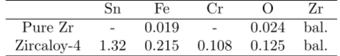
Table 1: Chemical composition (wt. %) of zirconium mate-rials used in this study.
Sn Fe Cr O Zr Pure Zr - 0.019 - 0.024 bal. Zircaloy-4 1.32 0.215 0.108 0.125 bal.
2.1.1. Pure zirconium
Pure zirconium results from the Kroll process in the form of a 3 mm thick plate. The raw zirconium sponge has first been arc-melted and cold-rolled with intermediate recrystallization treatments dur-ing 3 hours at 580◦C. After the last cold-rolling step, the same recrystallization treatment has been applied followed by a tensile test up to a strain of 1.5%. The purpose of this straining was to reach critical strain annealing phenomenon in order to ob-tain large grains [30, 31]. This straining was fol-lowed by an annealing at 840◦C during 24 hours. After this treatment, the mean grain size was 70 µm with a large dispersion around this value. The ma-terial texture exhibited hci axis mainly along the normal direction (ND) of the plate. Small samples, 3 mm long and 1 mm wide, were taken out of the plate with the long direction along ND, to activate hc + ai slip.
2.1.2. Zircaloy-4
Recrystallized Zircaloy-4 is used for light water reactor applications as guide tubes. These tubes have a thickness smaller than 1 mm and exhibit a strong texture with the hci axis of the grains close to the radial direction (RD) of the tube, in the AD-RD (AD: axial direction) plane. Such products are not suitable to study easily the activation of pyrami-dal hc + ai slip, as one has to pull the grains along directions close to the hci axis which are mainly along the radial direction of the thin tube. Because of the small thickness of the tube along the radial direction, it is not possible to machine small ten-sile test samples in this direction. This is the rea-son why an intermediate product of the fabrication process, called TREX for Tube Reduced Extrusion, has been used. This is a thick tube, with diameter of the order of 55 mm and thickness of the order of 10 mm. This material exhibits equi-axed grains with mean size of 6 µm and a low initial disloca-tion density, only of the order of 1011m−2. The hci
axis of the grains are mainly oriented in the RD-TD (TD: transverse direction) plane with the highest pole density along TD [32, 33]. Small dog-bone
specimens, 11.5 mm long and 2.3 mm wide, were machined by electrical discharge, with the tensile direction along TD. Therefore, thanks to the tex-ture, a large number of grains are expected to have their hci axis along the tensile direction.
2.2. In situ TEM straining experiments
Pure zirconium and Zircaloy-4 samples have been mechanically polished down to 0.1 mm thick and electropolished to make a small hole, using a mix-ture of 90% of ethanol and 10% of perchlorate acid at −10◦C. The thin area around the hole is only few
hundreds nanometer thick and is therefore suitable for TEM observations.
In situ straining experiments were performed at room temperature on both materials using a GATAN cooling and straining TEM sample holder on a JEOL 2010 operating at 200 kV. The thin foils were pasted on two ceramic rings or on copper grids at each ends to be pulled by the TEM holder. For Zircaloy-4, experiments have been also conducted at room temperature on a FEI Tecnai operating at 200 kV, using the commercial room temperature GATAN straining specimen-holder and the dog-bone TEM samples. On these two specimen hold-ers, one cross-head of the sample is fixed and the other cross-head is attached to a bar which ment is controlled by a motor. Typical displace-ments are 100 µm.
The experimental procedure is as follows. First, the orientation of various grains is analyzed until finding a grain with an orientation that satisfies two criteria: i) the hci axis must be close enough to the tensile direction (typically less than 10◦) so that hc + ai slip will be activated, ii) the grain can be tilted, in the limit of the tilt range and with the restriction of single-tilt allowed by the TEM sam-ple holder, so that a two beam diffraction condition with ~g = 0002 diffraction vector can be obtained. In this condition, the hai dislocations disappear and only hc + ai dislocations are observed. The number of grains that meet these two conditions appears to be rather limited, despite the effort to select mate-rials with adequate texture.
Once the grains have been selected, the displace-ment of the cross-head is progressively increased un-til hc + ai dislocation motion is observed. The dis-placement is then maintained constant or slightly decreased and the dislocation motion is recorded using an ORIUS wide angle GATAN camera op-erating at ten images per second or a megaview III camera operating with 50 images per second.
Supplementary video related to this article can be found at [INSERT DOI].
For some experiments, it has been possible to achieve extinction conditions for the hc + ai dis-locations, by tilting the sample. This allows the determination of the exact Burgers vector of the dislocation. For most of experiments only the glide plane of the dislocation was deduced, without am-biguity, using two informations : i) the orientation of the slip traces and ii) the evolution of the dis-tance between the two slip traces when tilting the thin foil. From this last measurement, the thickness of the thin foil can also be estimated. Furthermore, when cross-slip was observed, the Burgers vector of the dislocation has been deduced from the knowl-edge of the two gliding planes.
3. Results in recrystallized Zircaloy-4 Besides the in situ TEM straining experiments described below, some post mortem observations on the same recrystallized Zircaloy-4 have been con-ducted after tensile tests to check that the behav-ior of hc + ai dislocations characterized in situ in thin foils concurs with the dislocation microstruc-ture obtained after straining macroscopic samples. These post mortem observations are described in Appendix A.
During the in situ experiments, the observation of hc + ai dislocation motion was always associated with the observation of twinning which often oc-curred after hc + ai dislocation glide. The twin-ning system was [1011]{1012} as expected in ten-sion in zirconium alloys at room temperature [34– 36]. Appendix B describes an analysis of one twin event where it has been possible to measure the twin propagation and thickening velocity. In the following, we only focus on the description of hc+ai dislocation glide.
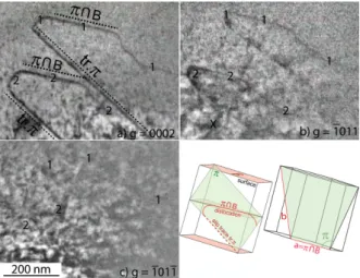
3.1. Glide planes and dislocation orientation Gliding hc + ai dislocations in recrystallized Zircaloy-4 are shown in Figures 1 and 2. In Fig-ure 1, it has been possible to determine exactly the Burgers vector ~b using different tilts: the disloca-tions are visible with diffraction vectors ~g = 0002 and ~g = ¯1011, but invisible with ~g = ¯101¯1, thus showing unambiguously that ~b = 1/3 [1123]. The dislocation glide plane could be determined from the direction of the slip traces on the surface and from the variations of the projected size of the
Figure 1: Zircaloy-4 strained in situ at room temperature. The dislocations are observed using a diffraction vector (a) ~g = 0002, (b) ~g = ¯1011 and (c) ~g = ¯101¯1. The tensile axis is vertical on the picture and close to the normal of the basal plane noted B. Two dislocations denoted as 1 and 2 glide in a (0111) plane noted π. From the two possible Burgers vectors, the extinction shown in (c) gives 1/3 [1123] as the Burgers vector. It is observed that the dislocations tend to be aligned along the [1120] direction noted π ∩ B, which is the intersection of the first-order pyramidal glide plane and the basal plane.
Figure 2: In situ TEM observations of hc + ai dislocations gliding in two different pyramidal planes. The corresponding slip traces are shown with dashed white lines. For both slip systems, the dislocations are aligned along a h2110i direc-tion: the [2110] direction for the two short horizontal disloca-tions gliding in (0111) (slip plane in red in the stereographic projection) and the [1210] direction for the long horizontal dislocation gliding in (1011) (slip plane in blue). Possible 1/3 h1213i Burgers vectors are indicated by filled circles on the stereographic projection.
curved dislocation and of its slip traces with the tilt angle: these 1/3 [1123] dislocations glide in a (0111) first-order pyramidal planes (Fig. 1). All the slip traces analyzed during our in situ tensile tests lead to a first-order pyramidal plane. When several hc + ai slip systems were activated in the
same grain (Fig. 2), they all correspond to the first-order pyramidal slip plane. In all grains where hc+ai slip was activated, the corresponding Schmid factors were higher than or equal to 0.36, while the Schmid factors of hai prismatic slip systems was smaller than 0.01. As a consequence, no hai dislo-cations was observed at this stage in grains where hc + ai slip is activated, but hai dislocations could be observed in the surrounding grains. As plastic strain increases, some hai dislocations could some-times also be observed in the same grains as hc + ai dislocations, probably because of the complex me-chanical load coming from the deforming surround-ing grains, from the appearance of some cracks and from twinning, and also because of crystal rotation. But these hai dislocations clearly appear latter than hc + ai dislocations. We could see some hc + ai dis-location nucleated on grain boundaries or on twins. But most of the time, hc + ai dislocations are com-ing from thick areas of the thin foil which could not be imaged.
In all these in situ straining experiments (Figs. 1 and 2), it can be noticed that the dislocation lines exhibit straight segments perpendicular to the ~
g = 0002 diffraction vector. The hc + ai preferen-tially align in a direction defined by the intersection of their first-order pyramidal glide plane with the basal plane, that is, along an hai direction. This dislocation orientation is nearly edge with a char-acter θ defined by cos (θ) = a/2√a2+ c2. For Zr
(c/a = 1.593), this leads to θ = 75◦. 3.2. Dislocation mobility
In situ observations of the dislocation motion in recrystallized Zircaloy-4 show that the hc + ai dislo-cations aligned along the hai direction glide slowly in a rigid manner with occasionally the formation of macro-kinks. This can be seen on Fig. 3, where the hc + ai dislocation aligned in the hai direction is nearly horizontal and the slip traces are the diag-onal lines. Dislocation glide is better analysed on Figs. 3d and 3e which are obtained as subtraction of the same area observed at two different times so as to reveal the differences between the two images, and thus the dislocation motion in the time inter-val. Between the initial time t = 0 and t = 10 s, the nearly edge part of the hc + ai dislocation has kept its straight hai orientation while gliding viscously a distance ∼ 100 nm. At this time, this disloca-tion gets pinned in its middle with only one half keeping gliding in the following 7.4 s. This leads to the formation of a macro-kink. After the last frame
shown in Fig. 3, the dislocation suddenly escapes from the observation zone, with a much faster
mo-Figure 3: Glide of a hc + ai dislocation in the (0111) pyrami-dal plane. The same dislocation is observed at three different times: the dislocation is almost straight in (a) and (b) with a line direction close to [2110], whereas macro-kinks can be seen in (c). Figures (d) and (e) are obtained by subtrac-tion respectively of images (a) and (b) and of images (b) and (c). In these figures, the initial and final positions of the dislocation appear with black and white contrast respec-tively. The dislocation Burgers vector has been determined to be 1/3 [1123] among the two possible ones shown on the stereographic projection (f). See video as a supplementary material.
Figure 4: Jump of the screw part of the hc + ai dislocation shown in Fig. 3. The image subtraction (a) corresponds to a time interval of 0.1 s during which the screw part jumps a distance ∆L ' 123 nm whereas the part aligned in the [2110] direction moves slowly. The initial and final positions of the dislocation, as well as the associated slip traces, are sketched respectively in black and orange in (b).
Figure 5: Jump length distribution for the hc + ai disloca-tion shown in Fig. 3. The jumps have been measured on a time interval ∆t = 0.1 s in a viscous motion regime and the whole analyzed sequence lasts 49.2 s. The blue histograms correspond to the jumps of dislocation segments along the [2110] direction and the purple ones to all other directions.
Figure 6: Glide of hc + ai dislocations observed in the same zone as Fig. 1. The dislocation labeled 1 arrived in the ob-servation zone between images (a) and (b) in a time interval ∆t = 0.18 s. Its straight portion aligned in the hai direction noted π ∩ B is then moving slowly between images (b) and (c) in ∆t = 1.7 s. See video as a supplementary material.
tion. Such a fast motion of the nearly edge part of the hc + ai dislocation has been captured in an-other in situ straining experiment. In Fig. 6, one can see that the dislocation labeled 1 has arrived suddenly in the observation zone in a time interval ∆t = 0.18 s with a long part of the line aligned in the hai direction noted π ∩ B on Fig. 6d. In the following 1.7 s, the dislocation moves much more slowly (Fig. 6e). Two mechanisms, leading either to a slow viscous glide or to a fast sudden motion, seem to control the mobility of this nearly edge part of the hc + ai dislocation.
Other orientations of the hc + ai dislocation, in-cluding the screw part, glide more rapidly with larger jumps than the viscous motion of the hai ori-entation, as can be seen for instance on Fig. 4. The
shape of these dislocations segments with other ori-entations is much more rounded and appears to be driven by minimization of the line tension. Never-theless, a lot of pinning points can be seen (Figs 1, 4 and 6), showing that these segments are anchored on numerous localized point obstacles.
We have tried to evaluate the difference of mobil-ity in the viscous glide regime between the part of the hc + ai dislocation aligned along the hai direc-tion (nearly edge) and the other mixed-screw orien-tations for the sequence shown in Fig. 3. The glide distance ∆L between two frames (∆t = 0.1 s) is measured for each part of the dislocation (Fig. 4b). If the dislocation does not move in this time inter-val, this is added to the waiting time of the disloca-tion. The overall waiting time accounts for 70% of the sequence duration (∆t = 49.2 s). Only the time intervals corresponding to a dislocation motion are then analyzed, grouping measured glide distances by bins of width 10 nm so as to build a histogram showing jump frequency as a function of glide dis-tances both for the nearly edge and the other mixed orientations of the hc + ai dislocation (Fig. 5). It then clearly appears that there is a higher frequency of short jumps, smaller than 10 nm, for disloca-tion lines along the hai direcdisloca-tion than for the other mixed-screw parts, thus leading to a lower glide ve-locity of this near edge orientation. The large jump of 100 nm long of the mixed-screw part shown in Fig. 4 corresponds to the tail of the histogram.
3.3. Cross-slip
During in situ straining experiments, cross-slip of hc + ai dislocations has been observed. One of these cross-slip events is illustrated on Fig. 7, where the dislocation exhibits a light contrast and the slip traces a strong contrast. New slip traces appear with another orientation, coming from the initial slip traces. Both slip planes correspond to first-order pyramidal planes. When analyzing care-fully the sequence to understand the geometry of the cross-slip event, it is found out that there must be an obstacle along the track of the dislocation. This obstacle could be a nano-hydride, a small pre-cipitate or even a forest dislocation. Because ini-tially the dislocation is along the hai direction, it is nearly edge and it cannot cross-slip. When the gliding dislocation meets the obstacle, which seems to be between the middle and the bottom of the thin foil, it is pinned. The part on the left contin-ues to glide and bends towards the screw direction.
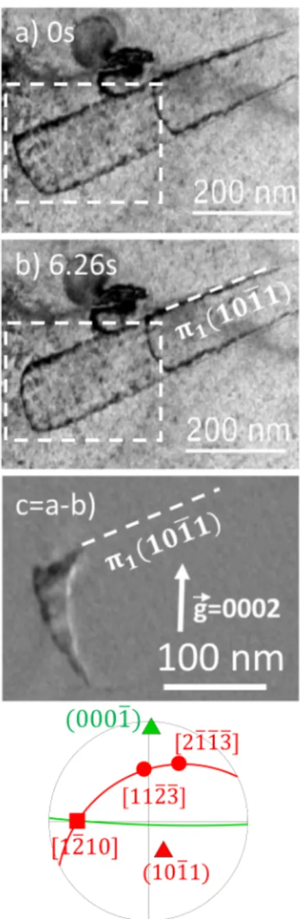
Figure 7: Dislocation cross-slip. (a,b) The dislocation with a Burgers vector 1/3 [2113] is initially gliding in the (1011) plane. Its interaction with an unknown defect makes it cross-slip. (c) The dislocation pinned by this defect continues gliding in the initial (1011) plane and in the cross-slipped (1101) plane. On the right sketches, the dislocation is drawn with a red and blue line when gliding respectively in its initial and crossed-slip plane. Bold black lines are the slip traces on the thin foil surface. See video as a supplementary material.
When aligned along the screw direction, the dislo-cation cross-slips in the other first-order pyramidal plane.
Four additional slip traces emerge between t = 0 (Fig. 7a) and t = 95 s (Fig. 7b). These traces cor-respond to two hc + ai dislocations which have also slipped in two other first-order pyramidal planes, leading to two slip traces on the top surface of the thin foil and two on the bottom surface. The slip
traces on the top and bottom surfaces are not par-allel because of the wedge shape of the thin foil. We have checked that these additional hc + ai dis-locations did not interact with the ones which have cross-slipped.
The process detailed here points out that hc + ai dislocations can cross-slip when they meet an obstacle and that the cross-slipped plane is also a first-order pyramidal plane.
3.4. Relaxation
When decreasing the stress applied on the spec-imen, by reducing the displacement of the cross-head from 120 to 100 µm, a dislocation has been found to move back on its track (Fig. 8). This dislocation relaxation has only been observed once in Zircaloy-4, but has also been observed in pure Zr. In the case of Zircaloy-4 shown on Fig. 8, it happens for a hc + ai dislocation which is far from the specific hai orientation. When decreasing the applied stress, the dislocation moves back to align in a direction closer to the screw orientation, since screw dislocations have a lower line energy than dis-locations with an edge character. This relaxation of the hc + ai is therefore probably driven by the line tension, thus further showing that the lattice fric-tion is not as strong for these orientafric-tions than for the hai direction. One also notices that the back motion of this hc + ai dislocation erases the slip traces on the thin foil, proving that, at least in this particular case, dislocation glide is well confined in a single crystallographic plane.
4. Results in pure Zr
The same in situ TEM straining experiments have been performed at room temperature on pure zirconium. Comparing these observations with the previous ones in Zircaloy-4 gives some insights on alloying effects on the mobility of hc + ai disloca-tions.
4.1. Dislocation motion
Like in Zircaloy-4, the slip planes of hc + ai dislo-cations have always been found in pure zirconium to correspond to the first-order pyramidal planes (Fig. 9). The dislocations also show some long rec-tilinear segments in the hai direction defined by the intersection of the pyramidal glide plane with the basal plane. Apart from this hai orientation, the dislocations are curved, with a shape driven by the
Figure 8: Relaxation of a hc + ai dislocation when the dis-placement of the sample holder is slightly decreased. Be-tween (a) the initial and (b) the final times, the dislocation on the left glides back in its slip plane and partially removes the slip trace on one of the thin foil surface. This is better seen on the zoom-in differential image (c). The stereographic projection of the grain indicates that the gliding dislocation is close to a screw orientation, its Burgers vector being ei-ther 1/3 [1123] or 1/3 [2113]. See video as a supplementary material.
line tension. One notices that in pure zirconium the straight portions are longer and better defined than in Zircaloy-4. This shape difference between both zirconium samples is a signature that the difference
of lattice friction between this hai direction and the other orientations of the hc + ai dislocations is stronger in pure zirconium than in Zircaloy-4. The presence of numerous solute elements in Zircaloy-4 slow-downs all hc + ai segments, thus reducing the mobility anisotropy of hc + ai dislocation. As pure zirconium contains very few impurities, this
Figure 9: Pure Zr strained at room temperature. The hc + ai dislocations are gliding in a pyramidal plane and are prefer-entially aligned in the hai direction defined by the intersec-tion of the pyramidal glide plane with the basal plane. Two dislocations denoted as 1 and 2 appear between t = 0 and 2.7 s: the dislocation 1 pulls two straight hai segments and ends with a curved line, while the dislocation 2 has slipped to the surface where it has left a slip trace tr. π. Between t = 2.7 and 3.4 s, the upper and right parts of dislocation 1 unlock and jump to a new position while its lower straight section extends to the surface without moving. Between t = 3.4 and 28 s the upper straight part of the dislocation slightly glides but without any lateral motion of macro-kinks present on this dislocation. See video as a supplementary material.
Figure 10: Detailed glide motion of the straight hai part of the hc + ai dislocation in pure Zr (same zone as Fig. 9). The dislocation “d” is composed of segments lying along the in-tersection of the pyramidal glide plane and the basal plane. Between (a) and (b), a lateral motion of a macro-kink is ob-served (see inclined arrows) whereas the whole dislocation is gliding between (b) and (c) without any motion of the macro-kink (see vertical arrows in). See video as a supplementary material.
mobility anisotropy appears more important, with an enhanced relative lattice friction acting against the glide of the straight hai orientation.
Like in Zircaloy-4, glide of the straight hai orien-tation of hc + ai dislocations leads to the creation of macro-kinks (Fig. 9) in pure zirconium. These macro-kinks can either glide along the dislocation line (Fig. 10d) or remain fixed while the dislocation moves slowly (Fig. 10e). Besides this viscous glide of the hai orientation, one also observes some large jumps, with therefore the same combination of slow and rapid motion as seen in Zircaloy-4.
A few cross-slip events have been also observed in pure zirconium. They appear, at first glance, less numerous than in Zircaloy-4, but a detailed statis-tical analysis would be needed to be able to really compare the occurrence of cross-slip in both mate-rials.
4.2. Friction stress
Some relaxation observations have been also per-formed in pure zirconium. These experiments have been used to estimate the friction stress acting against the glide of the hai orientation and of the other orientations, thus characterizing the mobility anisotropy. The friction stress originates from the dislocation core structure, like a possible non planar dissociation, and also from the dislocation interac-tion with the solute atoms present in the zirconium matrix.
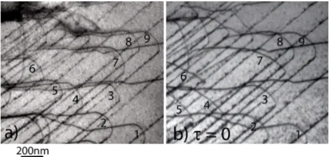
When the applied stress τa is removed, one
ob-served that the curved parts of the dislocations are gliding back and that their curvature radius in-creases (Fig. 11). This variation of the curvature radius can be used to estimate the applied stress and the friction stress τf acting against the glide
Figure 11: Relaxation of hc + ai dislocation in pure zir-conium. The applied strain has been released between (a) and (b), leading to a back motion of the dislocations and an increase of their curvature radius.
motion of these curved segments. Using the pro-gram Disdi based on line tension calculations in anisotropic elasticity [37], one can deduce from the dislocation curvature the line tension stress τl. The
shape of the loops 1 to 9 under an applied stress τa shown on Fig. 11a corresponds to a line
ten-sion stress τl between 100 and 150 MPa. When the
stress is relieved (τa = 0 on Fig. 11b), we obtain a
line tension stress τl between 25 and 50 MPa. The
applied stress is always in equilibrium with the line tension and the friction stresses, τa = τl+ τf. We
therefore deduce a friction stress τf = 37 ± 13 MPa
acting again the glide of curved dislocation and an applied stress τa = 160 ± 40 MPa. This
ap-plied stress corresponds to the friction stress acting against the motion of the straight hai parts of the dislocation, because the line tension is zero for a straight dislocation, thus confirming that this fric-tion stress is much higher for this particular orien-tation.
5. Discussion
5.1. Glide planes and cross-slip
Only glide in first-order pyramidal planes has been observed in our experiments, both in pure zir-conium and in Zircaloy-4. This agrees with previous TEM observations [7, 8, 10, 11, 13–16] which invari-ably report the same glide plane for hc + ai disloca-tions. Only Long et al. [16] have shown that cross-slip in second order pyramidal plane is also possi-ble, with nevertheless first-order pyramidal plane being the main glide plane. As the zirconium al-loy studied by Long et al. contains 2.5 wt.% Nb, it is possible that niobium addition promotes the activation of this secondary slip system for hc + ai dislocations.
Cross-slip events between the two first-order pyramidal planes shared by a single hc + ai direc-tion have been observed in Zircaloy-4 and in pure zirconium in our experiments, and also in Zr-2.5Nb alloy by Long et al. [14–16]. Cross-slip activation at room temperature may look surprising as the dis-location microstructure shows disdis-locations mostly aligned in a direction far from the screw orienta-tion, which should prevent cross-slip. Nevertheless, cross-slip has been observed in our experiments only when the dislocation meets an obstacle, this obsta-cle forcing the dislocation to adopt locally a screw orientation which can then cross-slip. As hc+ai dis-locations gliding in first-order pyramidal planes are thought to be dissociated in two partials separated by a stable stacking fault [38], the obstacle should also help the dislocation constriction necessary for its propagation then in the cross-slipped plane, in the same way as the Friedel-Escaig mechanism op-erating in face-centered cubic metals [39, 40]. As less obstacles are present in pure zirconium than in Zircaloy-4, one should expect cross-slip being less active in pure zirconium. This looks in agreement with our observations, although, as mentioned ear-lier, a detailed statistical analysis would be needed to truly compare cross-slip activity in the two ma-terials.
5.2. Straightening along hai direction
One key feature of the glide motion of hc + ai dislocations is the strong lattice friction existing for the orientation corresponding to the intersec-tion of the pyramidal glide plane with the basal plane, leading to long straight dislocations aligned along this hai direction. This important friction ex-ists both in pure zirconium and in Zircaloy-4, thus showing that it certainly derives from an intrinsic core property of this specific orientation. As men-tioned in the introduction, this behavior is not spe-cific to zirconium, but can be found in other hcp metals. In Mg, it has been observed that hc+ai dis-locations gliding in second-order pyramidal planes may lock themselves by a non-conservative dissoci-ation in the basal plane when their line direction belongs to this plane [18], a mechanism which has been well described by elasticity [41] and atomistic simulations [21]. For hc + ai dislocations gliding in first-order pyramidal plane, atomic simulations [42–44] predict that the same locking mechanism operates, with a non conservative dissociation in the basal plane of the hc + ai in two partial dis-locations separated by a basal I1 stacking fault:
1/3 h1213i → 1/6 h2203i + 1/6 h0223i. Elastic cal-culations of the energy variation induced by this dissociation predict that it is also favorable in Zr [45], thus potentially explaining the locking of the hc + ai when they meet the basal plane.
However our in situ experiments provide some clues that the lattice friction of this hai orientation may have a different origin in zirconium. Locking of edge hc+ai dislocations in Mg by a non conservative dissociation in the basal plane has been correlated with the emission of basal prismatic loops with a I1
stacking fault [18, 46]. No such basal I1 loops were
detected in our in situ TEM straining experiments, neither in pure zirconium nor in Zircaloy-4. As the emission of these loops is intimately related to the non conservative dissociation of hc + ai dislocations in the basal planes, this may be an indication that such a non conservative dissociation does not op-erate in zirconium at room temperature. Besides, contrary to magnesium [18], hc + ai dislocations in-tersecting the basal plane are not completely ses-sile in zirconium but only suffer a reduced mobility compared to other orientations. Finally, if hc + ai dislocations lock themselves in the hai direction by a non conservative dissociation, i.e. by climb of partial dislocations in the basal plane, one would expect that the locking efficiency would depend on the arrest time. This would lead to dynamic strain ageing and to plastic instabilities which we did not observe in our in situ experiments. The large lat-tice friction of this hai orientation of the hc + ai dislocation should therefore result from a different mechanism in zirconium.
This non conservative dissociation is not the solely possible mechanism leading to a lattice fric-tion. It has been also observed in Mg that hc + ai dislocation may emit an hai dislocation gliding in the basal plane to leave behind a sessile hci dislo-cation [18]. Nevertheless, this will lead once again to the permanent locking of the hc + ai dislocation and not only to a reduced mobility. Besides, the ex-tinction tests performed during our in situ experi-ments (Fig. 1) clearly indicate that the dislocations aligned along the hai direction have a hc + ai and not a hci Burgers vector. The possible dissociation hc + ai → hci + hai appears therefore not compati-ble with our observations, unless the hci and hai are so tightly bound that they could not separate and should be considered as a single dislocation [44].
Without going to the emission of a perfect basal hai dislocation, Numakura et al.[42, 43] have shown that hc+ai dislocations intersecting the basal plane
can emit a single Shockley partial trailing a basal I2 stacking fault. The corresponding dissociation,
1/3 h1213i → 1/3 h0110i + 1/3 h1103i, does not re-quire climb of the partial dislocations and leads to a non planar core with a stacking fault in the basal and in the pyramidal planes. Atomistic simulations relying on a generic interatomic potential for hcp metals [42, 43] show that this core is more stable than the planar core dissociated in the pyramidal plane, but that it recombines in this planar core under an applied stress to easily glide then in the pyramidal plane. This non planar core could there-fore explain the lattice friction of the hai orienta-tion. Its ability to transform in a planar glissile core is also compatible with the jerky glide motion sometimes seen for this hai orientation.
5.3. Macro-kinks
One characteristic of the gliding hc + ai dislo-cations when they are aligned in the hai direction is the presence of macro-kinks on these otherwise straight segments. Recent in situ TEM compres-sion experiments performed in Mg [23] have evi-denced the same macro-kinks on the straight por-tions of hc + ai dislocapor-tions, leading to “stair-like” shapes. Although hc+ai dislocations are not gliding on the same pyramidal plane in Zr and Mg, their glide motion induces the formation of macro-kinks in both metals. We can reasonably exclude that these macro-kinks are a by-product of a reaction with hai dislocations as extinction tests in TEM ob-servations showed that they have the same hc + ai Burgers vector as the whole dislocation lines. They could arise from a local change of configurations of the hc + ai dislocation, between an almost ses-sile core corresponding to the straight segments and a glissile core for the kinks. These macro-kinks are less numerous in pure zirconium than in Zircaloy-4, leading to longer straight dislocations in the former case. Their interaction with the different solute atoms present in solid solution hinder their motion, thus leading to a stronger pinning of these macro-kinks in Zircaloy-4 than in pure zirconium. 5.4. Lattice friction
Our line tension measurements indicate a fric-tion stress of 160 ± 40 MPa acting against glide of the straight part of hc + ai dislocations in pure zirconium. This friction has both an intrinsic ori-gin probably due to a complex core of the hc + ai dislocation for the hai orientation as discussed be-fore and an extrinsic one arising from interaction
with solute atoms. This friction stress of the less mobile segments should correspond to the yield stress of hc + ai pyramidal slip at room tempera-ture. Modeling with crystal plasticity their micro-cantilevers bending experiments, Gong et al. [17] obtained for the same slip system a much higher value, 532 ± 58 MPa, in a commercial pure zirco-nium. With a higher level of solute elements in commercial pure zirconium than in the pure zirco-nium used in our experiments, in particular oxygen concentration which is four times higher, this yield stress difference indicates a strong influence of al-loying elements. This is further supported by the strongest pinning of gliding dislocations observed in Zircaloy-4 than in pure zirconium.
This reduced mobility of hc + ai dislocations in alloyed zirconium may appear at first glance in con-tradiction with the study of Jensen and Backofen [6] who observed that plastic strain along the hci axis was mostly accommodated by twinning below 300◦C in pure zirconium whereas only hc + ai slip was activated in Zircaloy-4 with very few compres-sive twins. Although solute elements further hinder glide of hc+ai dislocations, this hardening contribu-tion appears less important than the impact of the same solute elements on twinning with the suppres-sion of twinning by impurities in zirconium [47], in particular oxygen which addition strongly decreases twin activity [36].
6. Conclusions
In situ TEM straining experiments performed both in pure zirconium and in Zircaloy-4 have shown that hc + ai dislocations glide exclusively in first-order pyramidal planes at room temperatures, with some cross-slip events between two pyramidal planes sharing the same hc + ai direction. A charac-teristic feature of the microstructure is that hc + ai dislocations align in the hai direction defined by the intersection of their glide plane with the basal plane, leading to long straight dislocations. Dislo-cations segments aligned along this orientation ex-perience a higher lattice friction than others, with a friction stress estimated to 160 ± 40 MPa for the hai orientation instead of 37 ± 13 MPa for others in pure zirconium. This hai orientation exhibits two different glide motions, either viscous or jerky, and its frequent pinning in localized points leads to the creation of macro-kinks. The same dynamic behav-ior of hc + ai dislocations has been observed in pure zirconium and in Zircaloy-4, except for a highest
friction acting against the motion of all characters in Zircaloy-4 because of the numerous alloying el-ements in solid solution. The mechanisms control-ling the mobility of hc + ai dislocations in zirconium show strong similarities with the ones operating in other hcp metals, in particular magnesium despite a different glide plane.
Acknowledgments - The authors thank Fram-atome for providing the raw Zr sponge and the Zircaloy-4 TREX tube, D. Nunes and S. Urvoy (SRMA/CEA) for the preparation of the pure Zr samples and B. Arnal (SRMA/CEA) for thin foils preparation. This work is funded by the French Tripartite Institute (CEA-EDF-Framatome) through the GAINE project.
Appendix A. Post-mortem observations
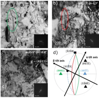
Figure A.12: Post mortem observation of hc + ai disloca-tions after conventional tensile test. The region is observed with three different tilt angles α and β corresponding to the diffraction vectors (a) ~g = 0002, (b) ~g = ¯1101 and (c) ~
g = 0¯111. The color circles in (a) and (b) evidence the same hc + ai dislocation. The white circle in (c) shows the posi-tion of the out of contrast dislocaposi-tion since the diffracposi-tion vector extinguishes the dislocation. The planes, observed edge-on in (a) and (b) for different tilts, containing the dis-location lines are shown by the corresponding color lines in the stereographic projection (d) at zero tilt. Therefore, this dislocation with 1/3 [1123] Burgers vector glides in (1011) plane and is aligned along the [1210] direction.
Besides the in situ TEM experiments described in the main text, some post mortem observations have been
carried out. The purpose was to check that the dis-location behavior observed in situ in thin foils is typ-ical of bulk plasticity. To this aim, conventional ten-sile tests on dog-bone Zircaloy-4 specimens taken out of the TREX tube with the tensile axis along the trans-verse direction have been performed at 350◦C up to a deformation of 4%. Strained samples have been then observed with a JEOL 2100 TEM operating at 200 kV. TEM observation with a ~g = 0002 diffraction vec-tor allows the extinction of all hai dislocations to im-age only dislocations with a hci component. Such a post mortem observation is shown in Fig. A.12. Us-ing other diffraction vectors, in particular ~g = 0¯111 for which the dislocation becomes invisible (Fig. A.12c), we could evidence that this dislocation is not pure hci, but is a hc + ai dislocation with 1/3 [1123] Burgers vector. Stereoscopic analysis of this dislocation further showed that it is lying in the (1011) first-order pyramidal plane. This hc + ai is mainly aligned along an hai direction corresponding to the intersection of its pyramidal glide plane with the basal plane. All our post mortem obser-vations, like Fig. A.12, reveal the same properties for hc + ai dislocations, in full agreement with the behavior observed during in situ experiments.
Appendix B. Twinning
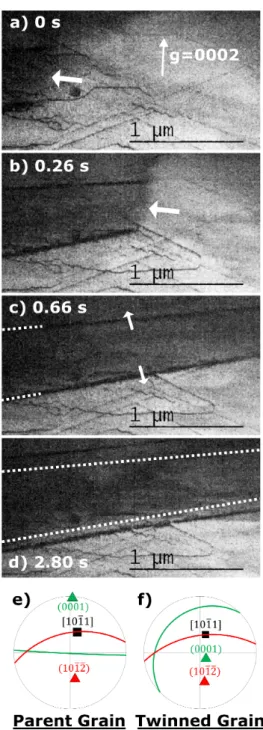
Twining was observed in situ in Zircaloy-4. In one case, the propagation of the twin and its thickening were slow enough to be analyzed (Fig. B.13). The forefront of the twin appears to be very diffuse, with-out any distinct contrast, whereas the edge of the twin exhibits a strong contrast. The velocity of the prop-agation of the twin forefront was evaluated measuring the distance between each frame, taken every 0.1 s. Be-cause of the rapid velocity of the twin forefront, there are only 6 frames to measure the instantaneous velocity which were equal to 1.24, 1.60, 2.86, 4.27 and 6.03 µm/s. Then, after the rapid propagation of the forefront of the twin, the twin is observed to thicken. The thickening velocity in the direction perpendicular to the twin in-terface is found to be equal to 33.3 nm/s. The twin ori-entation with respect to the parent grain was analyzed: this is a tension twin, corresponding to the twinning system [1011](1012).
References
[1] A. T. Motta, D. R. Olander, Light water reactor materi-als, American Nuclear Society, La Grange Park, Illinois, 2017.
[2] D. Caillard, J. L. Martin, Thermally activated mech-anisms in crystal plasticity, Pergamon, Amsterdam, 2003.
[3] E. Clouet, D. Caillard, N. Chaari, F. Onimus, D. Rod-ney, Dislocation locking versus easy glide in titanium
Figure B.13: Nucleation and growth of a {1012} twin. The propagation of the twin tip can be seen between images (a) and (c), while the thickening of the twin is observed, on a much longer timescale, between images (c) and (d). The stereographic projection of (e) the parent and (f) the twined crystal indicates that the twinning system is [1011](1012). See video as a supplementary material.
and zirconium, Nat. Mater. 14 (2015) 931–936. doi: 10.1038/nmat4340.
[4] D. Caillard, M. Gaum´e, F. Onimus, Glide and cross-slip of a -dislocations in Zr and Ti, Acta Mater. 155 (2018) 23–34. doi:10.1016/j.actamat.2018.05.038.
[5] E. Tenckhoff, Operation of dislocations with hc+ai type Burgers vector during deformation of zirconium single-crystals, Z. Metallkde. 63 (1972) 192.
[6] J. A. Jensen, W. A. Backofen, Deformation and fracture of alpha zirconium alloys, Can. Metall. Q. 11 (1972) 39– 51. doi:10.1179/cmq.1972.11.1.39.
[7] A. Akhtar, Compression of zirconium single crystals parallel to the c-axis, J. Nucl. Mater. 47 (1973) 79–86. doi:10.1016/0022-3115(73)90189-X.
[8] O. T. Woo, G. J. C. Carpenter, S. R. MacEwen, hci-component dislocations in zirconium alloys, J. Nucl. Mater. 87 (1979) 70–80. doi:10.1016/0022-3115(79) 90126-0.
[9] R. A. Holt, M. Griffiths, R. W. Gilbert, c-component dislocations in Zr-2.5 wt% Nb alloy, J. Nucl. Mater. 149 (1987) 51–56. doi:10.1016/0022-3115(87)90497-1. [10] P. Merle, Evidence of pyramidal slip mode in cold-rolled
zircaloy-4 sheets, J. Nucl. Mater. 144 (1987) 275–277. doi:10.1016/0022-3115(87)90040-7.
[11] H. Numakura, Y. Minonishi, M. Koiwa, h¯1¯123i{10¯11} slip in zirconium, Philos. Mag. A 63 (1991) 1077–1084. doi:10.1080/01418619108213938.
[12] R. J. McCabe, E. K. Cerreta, A. Misra, G. C. Kaschner, C. N. Tom´e, Effects of texture, temperature and strain on the deformation modes of zirconium, Philos. Mag. 86 (2006) 3595–3611. doi:10.1080/14786430600684500. [13] F. Long, M. R. Daymond, Z. Yao, Deformation
mech-anism study of a hot rolled Zr-2.5Nb alloy by trans-mission electron microscopy. I. Dislocation microstruc-tures in as-received state and at different plastic strains, J. Appl. Phys. 117 (2015) 094307. doi:10.1063/1. 4913605.
[14] F. Long, M. R. Daymond, Z. Yao, M. A. Kirk, De-formation mechanism study of a hot rolled Zr-2.5Nb alloy by transmission electron microscopy. II. In situ transmission electron microscopy study of deformation mechanism change of a Zr-2.5Nb alloy upon heavy ion irradiation, J. Appl. Phys. 117 (2015) 104302. doi: 10.1063/1.4913614.
[15] F. Long, L. Balogh, M. R. Daymond, Evolution of dislo-cation density in a hot rolled Zr–2.5Nb alloy with plastic deformation studied by neutron diffraction and trans-mission electron microscopy, Philos. Mag. 97 (2017) 2888–2914. doi:10.1080/14786435.2017.1356940. [16] F. Long, J. Kacher, Z. Yao, M. R. Daymond, A
to-mographic TEM study of tension-compression asymme-try response of pyramidal dislocations in a deformed Zr-2.5Nb alloy, Scr. Mater. 153 (2018) 94–98. doi: 10.1016/j.scriptamat.2018.04.043.
[17] J. Gong, T. B. Britton, M. A. Cuddihy, F. P. Dunne, A. J. Wilkinson, hai prismatic, hai basal, and hc+ai slip strengths of commercially pure Zr by micro-cantilever tests, Acta Mater. 96 (2015) 249–257. doi:10.1016/j. actamat.2015.06.020.
[18] J. F. Stohr, J. P. Poirier, Etude en microscopie´ ´
electronique du glissement pyramidal {11¯22}h11¯23i dans le magn´esium, Philos. Mag. 25 (1972) 1313–1329. doi:10.1080/14786437208223856.
[19] J. Geng, M. Chisholm, R. Mishra, K. Kumar, The struc-ture of hc+ai type dislocation loops in magnesium,
Phi-los. Mag. Lett. 94 (2014) 1–10. doi:10.1080/09500839. 2014.916423.
[20] J. Geng, M. Chisholm, R. Mishra, K. Kumar, An elec-tron microscopy study of dislocation structures in Mg single crystals compressed along [0001] at room tem-perature, Philos. Mag. 95 (2015) 3910–3932. doi: 10.1080/14786435.2015.1108531.
[21] Z. Wu, W. A. Curtin, The origins of high hardening and low ductility in magnesium, Nature 526 (2015) 62–67. doi:10.1038/nature15364.
[22] Z. Wu, R. Ahmad, B. Yin, S. Sandl¨obes, W. A. Curtin, Mechanistic origin and prediction of enhanced ductility in magnesium alloys, Science 359 (2018) 447–452. doi: 10.1126/science.aap8716.
[23] D. Zhang, L. Jiang, X. Wang, I. J. Beyerlein, A. M. Minor, J. M. Schoenung, S. Mahajan, E. J. Lavernia, In situ transmission electron microscopy investigation on hc + ai slip in Mg, J. Mater. Res. 34 (2019) 1499– 1508. doi:10.1557/jmr.2018.487.
[24] Y. Minonishi, S. Morozumi, H. Yoshinaga, {11¯22}h¯1¯123i slip in titanium, Scr. Metall. 16 (1982) 427–430. doi:10.1016/0036-9748(82)90166-1. [25] H. Numakura, Y. Minonishi, M. Koiwa, h¯1¯123i{1011}
slip in titanium polycrystals at room temperature, Scr. Metall. 20 (1986) 1581–1586. doi:10.1016/ 0036-9748(86)90399-6.
[26] F. Long, L. Balogh, D. W. Brown, P. Mosbrucker, T. Skippon, C. D. Judge, M. R. Daymond, Effect of neutron irradiation on deformation mechanisms operat-ing duroperat-ing tensile testoperat-ing of Zr–2.5Nb, Acta Mater. 102 (2016) 352–363. doi:10.1016/j.actamat.2015.09.032. [27] D. Caillard, M. Rautenberg, X. Feaugas, Disloca-tion mechanisms in a zirconium alloy in the high-temperature regime: An in situ TEM investigation, Acta Mater. 87 (2015) 283–292. doi:10.1016/j. actamat.2015.01.016.
[28] J. Drouet, L. Dupuy, F. Onimus, F. Mompiou, A di-rect comparison between in-situ transmission electron microscopy observations and dislocation dynamics sim-ulations of interaction between dislocation and irradi-ation induced loop in a zirconium alloy, Scr. Mater. 119 (2016) 71–75. doi:10.1016/j.scriptamat.2016. 03.029.
[29] M. Gaum´e, P. Baldo, F. Mompiou, F. Onimus, In-situ observation of an irradiation creep deformation mecha-nism in zirconium alloys, Scr. Mater. 154 (2018) 87–91. doi:10.1016/j.scriptamat.2018.05.030.
[30] D. Chaubet, J. Fond`ere, B. Bacroix, Strain-anneal growth of zr 701 large crystals, Mater. Sci. Eng. A 300 (2001) 245–253. doi:10.1016/S0921-5093(00)01785-8. [31] K. Y. Zhu, D. Chaubet, B. Bacroix, F. Brisset, A study of recovery and primary recrystallization mechanisms in a Zr–2Hf alloy, Acta Mater. 53 (2005) 5131–5140. doi:10.1016/j.actamat.2005.07.034.
[32] L. Tournadre, F. Onimus, J.-L. B´echade, D. Gilbon, J.-M. Clou´e, J.-P. Mardon, X. Feaugas, O. Toader, C. Bachelet, Experimental study of the nucleation and growth of c-component loops under charged particle ir-radiations of recrystallized zircaloy-4, J. Nucl. Mater. 425 (2012) 76—-82. doi:10.1016/j.jnucmat.2011.11. 061.
[33] N. Gharbi, F. Onimus, D. Gilbon, J.-P. Mardon, X. Feaugas, Impact of an applied stress on c-component loops under Zr ion irradiation in recrystallized Zircaloy-4 and M5 , J. Nucl. Mater. 467 (2015) 785–801. doi:R
10.1016/j.jnucmat.2015.10.009.
[34] E. J. Rapperport, C. S. Hartley, Deformation modes of zirconium at 77◦, 575◦, and 1075◦K, Trans. AIME 218 (1960) 869–876.
[35] M. H. Yoo, J. K. Lee, Deformation twinning in h.c.p. metals and alloys, Philos. Mag. A 63 (1991) 987–1000. doi:10.1080/01418619108213931.
[36] M. Viltange, M. Biget, O. Dimitrov, Influence de l’oxyg`ene sur le maclage, la production et la restau-ration de d´efauts sp´ecifiques dans le zirconium deform´e `
a tr`es basse temp´erature, J. Nucl. Mater. 127 (1985) 231—-238. doi:10.1016/0022-3115(85)90360-5. [37] J. Douin, P. Veyssi`ere, P. Beauchamp, Dislocation line
stability in Ni3Ai, Philos. Mag. A 54 (1986) 375–393.
doi:10.1080/01418618608240722.
[38] D. Rodney, L. Ventelon, E. Clouet, L. Pizzagalli, F. Willaime, Ab initio modeling of dislocation core properties in metals and semiconductors, Acta Mater. 124 (2017) 633–659. doi:10.1016/j.actamat.2016.09. 049.
[39] J. Friedel, Dislocations, Pergamon Press, Oxford, 1964. [40] B. Escaig, Sur le glissement d´evi´e des disloca-tions dans la structure cubique `a faces centr´ees, J. Phys. Paris 29 (1968) 225–239. doi:10.1051/jphys: 01968002902-3022500.
[41] S. Agnew, L. Capolungo, C. Calhoun, Connections be-tween the basal I1 “growth” fault and hc + ai disloca-tions, Acta Mater. 82 (2015) 255–265. doi:10.1016/j. actamat.2014.07.056.
[42] H. Numakura, Y. Minonishi, M. Koiwa, Atomistic study of 1/3 h¯1¯123i {10¯11} dislocations in h.c.p. crys-tals. i. structure of the dislocation cores, Philos. Mag. A 62 (1990) 525–543. doi:10.1080/01418619008244917. [43] H. Numakura, Y. Minonishi, M. Koiwa, Atomistic
study of 1/3 h¯1¯123i {10¯11} dislocations in h.c.p. crys-tals. II. motion of the dislocations, Philos. Mag. A 62 (1990) 545–556. doi:10.1080/01418619008244917. [44] Z. Wu, W. Curtin, Intrinsic structural transitions of
the pyramidal I hc + ai dislocation in magnesium, Scripta Mater. 116 (2016) 104–107. doi:10.1016/j. scriptamat.2016.01.041.
[45] Z. Wu, B. Yin, W. A. Curtin, Energetics of dislocation transformations in hcp metals, Acta Mater. 119 (2016) 203–217. doi:10.1016/j.actamat.2016.08.002. [46] S. Sandl¨obes, M. Fri´ak, S. Zaefferer, A. Dick, S. Yi,
D. Letzig, Z. Pei, L.-F. Zhu, J. Neugebauer, D. Raabe, The relation between ductility and stacking fault en-ergies in Mg and Mg–Y alloys, Acta Mater. 60 (2012) 3011–3021. doi:10.1016/j.actamat.2012.02.006. [47] A. M. Garde, E. Aigeltinger, R. E. Reed-Hill,
Rela-tionship between deformation twinning and the stress-strain behavior of polycrystalline titanium and zirco-nium at 77 K, Metall. Trans. 4 (1973) 2461–2468. doi: 10.1007/bf02669391.
![Figure 4: Jump of the screw part of the hc + ai dislocation shown in Fig. 3. The image subtraction (a) corresponds to a time interval of 0.1 s during which the screw part jumps a distance ∆L ' 123 nm whereas the part aligned in the [2110]](https://thumb-eu.123doks.com/thumbv2/123doknet/13707134.434061/6.892.97.427.229.630/figure-jump-dislocation-subtraction-corresponds-interval-distance-aligned.webp)
![Figure 7: Dislocation cross-slip. (a,b) The dislocation with a Burgers vector 1/3 [2113] is initially gliding in the (1011) plane](https://thumb-eu.123doks.com/thumbv2/123doknet/13707134.434061/7.892.464.792.166.744/figure-dislocation-cross-dislocation-burgers-vector-initially-gliding.webp)