HAL Id: inria-00586851
https://hal.inria.fr/inria-00586851
Submitted on 18 Apr 2011
HAL is a multi-disciplinary open access
archive for the deposit and dissemination of
sci-entific research documents, whether they are
pub-lished or not. The documents may come from
teaching and research institutions in France or
abroad, or from public or private research centers.
L’archive ouverte pluridisciplinaire HAL, est
destinée au dépôt et à la diffusion de documents
scientifiques de niveau recherche, publiés ou non,
émanant des établissements d’enseignement et de
recherche français ou étrangers, des laboratoires
publics ou privés.
Scheduling Multi Clock Real Time Systems: From
Requirements to Implementation
Marie-Agnès Peraldi-Frati, Julien Deantoni
To cite this version:
Marie-Agnès Peraldi-Frati, Julien Deantoni. Scheduling Multi Clock Real Time Systems: From
Re-quirements to Implementation. International Symposium on Object/Component/Service-oriented
Real-time Distributed Computing, Mar 2011, Newport Beach, United States.
pp.50; 57,
1
Scheduling Multi Clock Real Time Systems:
From Requirements to Implementation
Marie-Agn`es Peraldi-Frati
∗†, Julien DeAntoni
∗† ∗Aoste Team-Project
I3S - UMR6070 - UNS CNRS
2000, route des Lucioles - Les Algorithmes - bt. Euclide B
BP 121 - 06903 Sophia Antipolis Cedex - France
Email: [email protected], [email protected]
†INRIA Sophia Antipolis M´editerran´ee
2004 route des Lucioles - BP 93
06902 Sophia Antipolis Cedex
Abstract
This paper presents an approach for modeling simulating and analyzing multi clocks real time systems during the different steps of a design. These steps range from the first requirements to a model allocated on a specific execution platform. TheUML MARTEprofile and theCCSLlanguage are used together to specify the causal and temporal characteristics of the software as well as the hardware parts of the system. The TIMESQUAREenvironment allows a simulation of such specification and the detection of potential errors and deadlocks. When the specification refinement is finished, to prove the specification correctness, theCCSL
specification is used to generate a synchronous model and some observers in Esterel. We illustrate the approach through a spark ignition control system.
Index Terms
logical time, multi-clock systems, requirement modeling, scheduling analysis.
I. INTRODUCTION
Real Time Embedded Systems (RTES) are in charge of the control of physical processes characterized by their own dynamics. This control must comply with timing constraints - sometimes stringent ones- imposed by the system. It is crucial to address these timing issues as early as possible in the development process to detect inconsistencies in the requirements or in the constraints and to capture changes in the system. It means that a designer will be able to validate that system meets the timing requirements imposed by the environment at any step in the development process. In the automotive domain, design processes are based on a multi-level design cycle. This cycle relies on an ADL (architecture description language) at the requirement, analysis and design levels and on specific APIs at the implementation level. Some examples of significant research projects in this area include EAST ADL2 [1], [2], [3] at the vehicle, analysis and design levels and AUTOSAR [4] at the implementation level.
In current practice, timing issues are mostly addressed - in the best case - at the very end of the design phase or more late during the implementation level i.e. when the system is composed of a set of tasks (preemptable or not) running on specific and possibly distributed execution resources (like ECU: Electronic Control Unit) or by purely concurrent modules implemented in hardware.
For timing, a wide range of analytical techniques can be applied [5], [6], [7], [8] to first compute the Worst and Best Case Execution Time depending on the ECU and second to verify if tasks can be scheduled according to their temporal parameters. The detection of infeasible requirements at the implementation level may involve important changes in a design increasing the cost of the system.
Current practice begins the development of RTES with high level models which capture the software and hardware models separately. Models are refined in several steps by adding details about functionalities and hardware characteristics. At each step, functional requirements can be traced to ensure a correct refinement. The hardware platform can be introduced and refined like the other parts of the system, or developed independently and allocated by the software elements. At the end of this refinement, schedulability techniques can be applied on models by extracting the information needed by the scheduling analysis [9].
Schedulability techniques and temporal validation of the system are still considered late in the development process. It should be also possible to apply preliminary analysis on the system at the very beginning of the design phase; even before having any details about the hardware platforms. Such analysis will allow to detect a design with inconsistent software architecture(even with truly concurrent executions). Finally, once the system is refined enough, it must be possible to extracted sufficient information and use it as an input of classical scheduling analysis.
An other important characteristic of real time embedded systems is that temporal information associated with functional parts and hardware parts are multi-time based. High level models should be able to capture such heterogeneity.
This paper proposes a multi-level and multi-clock design approach and analysis for real time systems. Our solution can be applied conjointly with UML and/or ADL (i.e: EAST ADL2 or AADL). The approach relies on logical time (from the
MARTE Time model [10], [11]) and Clock Constraint Specification Language (CCSL) [12], [13] as a mean to express: 1) the timing requirements, 2) the timed and functional causal constraints of the system, and 3) the constraints introduced by the execution platform. Such modeling of temporal constraints can be done at different steps of the development process. Timing requirements are translated into logical clocks constrained by CCSL specifications. Then, we add constraints that reflect the functional causality between the different events of the model. Finally, with the knowledge of the hardware platform and the decomposition of functionalities into tasks, other constraints can be incrementally added to model CPU clock and allocation/preemption of CPU w.r.t tasks execution. It is then possible to check the validity of the constraints against the requirements at any step of the refinement.
Another aspect of using the proposed approach is the ability to simulate and formally verify a design at the model level to detect possible deadlock or requirement violations.
The paper is organized as follows, first we give an overview of research results in the field of high level modeling and analyses of real time systems. We also present logical time and its different usages. The second section presents the Clock Constraint Specification Language (CCSL) and its associated simulation tool TIMESQUARE[14]. The third section presents an example as a support for presenting our approach. The last part shows how to use CCSL to model time critical systems and the different techniques we use to simulate and verify a design. Finally we give a conclusion and perspectives to this work.
II. RELATEDWORK
Capturing behavioral and structural requirements at the early stage of a design becomes a mandatory requirement of modern process design flow for real-time embedded systems. Several projects such as ATTEST2 [3], AADL-OSATE [15], AUTOSAR [4] or even SysML [16] have produced significant results for the development of sophisticated safety critical systems by providing environments that allow the structuring of requirements. Requirements are still expressed in a natural language but it is then possible to structure them together, for instance with refinement relations, or to link them to the model element(s) that deal with these requirements (like a component which satisfies a requirement or a scenario that verifies the requirement). These requirements are then expressed at the very beginning of the design phase. However, a main shortcoming concerns temporal requirements modeling and the difficulty of analyzing the temporal behavior of the system at the different stages of the development process.
Many approaches use specific annotations on a model to add the information required by scheduling analysis tools [9], [17], [18], [19]. These approaches provide temporal analysis on models but, as they lack precise temporal annotations at the early stage of the design, such analysis is usually done at the very last step of the design. Detecting error and inconsistency at the implementation level can be very costly.
TIMMO[20] project aims at overcoming this issue. TIMMO proposes the Timing Augmented Description Language (TADL [21]) aligned onAUTOSARto model time and express associated constraints at the analysis and design phases of a development process. According to this specification, a methodology to explore the timing features for a progressive and step by step system description has been proposed. Simulation tools [22], [23], connected to aTADLdescription, provides end-to-end delay scenario and deliver time stamps of tasks and functions calls. While the approach sounds really close to ours, such simulation and analysis are still applied too late in the development process; i.e., once the allocation phase of software components onto hardware is performed and the task model chosen. However, we believe that it is very complementary to our approach and convergences will be found between both approaches in the recently started TIMMO2 project.
Our approach differs from the previous ones with the fundamental concept of logical time. Logical time has proved its benefits in several domains. It was first introduced by Lamport to represent the execution of distributed systems [24]. It has then been extended and used in distributed systems to check the communication and causality path correctness [25]. During the same period, Logical time has also been intensively used in synchronous languages [26], [27] for its polychronous nature (i.e., based on several time references). In the synchronous domain it has proved to be adaptable to any level of description, from very flexible causal time descriptions to very precise scheduling descriptions [28]. Finally, the notion of logical time is often used every day when any event is taken as a reference. For instance, consider the sentence “Task 1 is started twice as often as Task 2”. An event is then expressed relative to another one, that is used as a reference. The reader can notice that no reference to physical time is given. However, if the duration between two Task1 start events is given, the periodicity duration of Task2 can be deduced. If one is increased, the other one is directly impacted. This is the main idea of using logical time. In this context, physical time is a particular case of logical time where the event generated by a physical clock is taken as reference. This model of time is precisely defined in the foundations of UML MARTE profile. Consequently, it can be applied in a standard way on any UML-based model. The main impact is the possibility to specify the logical events - that depict the dynamic of the system - at the same level than the UML-based structural elements. This modeling of timing features can be done in the preliminary phases of a design even if all the parameters of this design are not fully set up.
III. CCSL,A MEAN TO SPECIFY LOGICAL EVENT RELATIONS
As explained in the previous section, the UML MARTE profile defines a Time Model. This model allows specification of clocks, which represent a (possibly infinite) totally ordered set of instants noted I. In this model, clocks can be seen as events
and instants as event occurrences. These clocks can be logical or physical, dense or discrete. In the remainder of this paper we only consider discrete clocks, rather logical or physical.
For a discrete clock c1, we denote c1[k] the kthinstant of c1 where k ∈ N+\ {0}. TheMARTE time model also specifies Clock Constraints, which refer to at least two clocks in order to constrain the respective evolution of their instants.
CCSL (Clock Constraint Specification Language) has been first introduced in the annex of the MARTE profile. After many improvement,CCSL has now a formal semantics [12] that can be exploited to process a correct execution, if any, in the TIME -SQUAREtool [14]. If no correct execution can be processed, TIMESQUAREindicates the presence of a deadlock. Foundational
CCSLconstraints are defined in a kernel library.CCSLallows building new libraries and the definition of user-defined constraints by composing existing relations (from the kernel library or from other ones) in order to fit the constraints from a specific domain.
CCSL is a means of specifying constraints on the evolution of some clocks. Constraints can be either a relation or an expression. A relation can be synchronous or asynchronous. CCSL also provides a set of expressions whose goal is to define a new clock according to other clocks. In this paper we do not want to give all details about the semantics of CCSLbut a full description can be found in [12]. However, we informally describe the necessary material to intuit the language as well as the relations and expressions used in this document. An example of the user-level CCSL language is provided section V-F.
Clock relations are based on a reflexive and transitive instant relation named precedence and noted 4. From 4 four new instant relations are derived: Coincidence: ≡, Strict precedence: ≺, Independence: k, and Exclusion: #.
A clock relation is the generalization of an instant relation on all the instants of a clock. For instance, a clock precedence relation (denoted ≺ ) between two clocks a and b is asynchronous and specifies that for all natural numbers k, the kthinstant of a occurs before the kth of b: ∀k ∈ N+ \ {0}, a[k] 4 b[k]. Another example is the coincidence relation (denoted = ) between two clocks a and b that imposes a stronger synchronous dependency: the kthinstant of a must be coincident with the kthinstant of b: ∀k ∈ N+\ {0}, a[k] ≡ b[k]. The same mechanism applies for all relations. Informally, the exclusion relation (denoted # ) between two clocks a and b specifies that no instants of the clock a coincide with one of the clock b. The alternatesWithrelation (denoted ∼ ) between two clocks a and b specifies that instants of the clock b are interleaving instants of the clock a.
Expressions are directly defined on clocks. For instance, the isPeriodicOn expression takes three parameters: a clock specifying the super clock, a positive natural number specifying a period and a positive natural number specifying the offset. It results in a clock which is a subclock of the super clock and whose instants are always separated by period instants of the super clock. Moreover, the first instant of the resulting clock coincides with the of f setth instant of the super clock. Another expression used in this paper is delayedFor. It takes three parameters: a reference clock, which represents the clocks we want to delay; a counter clock, which represents the clock on which the delay is counted and a positive natural number, which specifies the number of ticks of the counter clock the reference clock is delayed.
ACCSLspecification is the conjunction of a set of constraints. As a result, because synchronous and asynchronous relations are used conjointly, the execution of aCCSLspecification is a partially ordered set of coincidence-equivalence classes of instants [11]. It is important to notice that, the addition of new constraints to a CCSL specification results in a new partial order that could lead either to the same partial order than the previous one (i.e., the new constraint has no impact) or to a refinement (i.e., a superset) of the previous partial order (i.e., it is “more ordered”). The reader should notice that, because clocks are defined in the MARTE profile and used in the CCSL semantics, they act as an interesting junction between the structural model and its behavior. In some sense, Clocks (that can be applied on every property or instance specification) generalize the concept of
UMLevents, which are used in only very specific parts of the model. IV. EXAMPLE DESCRIPTION
We consider the spark ignition control system of a car engine (simplified from an industrial example) to illustrate our approach. The objective is to provide the sparks ignition in the engine cylinders at the “good time”. This instant depends on several parameters such as the crankshaft (CRK) and the camshaft (CAM) rotation positions, a sensor that detects potential knock phenomenon, the temperature of the engine and the mode of the motor (warm-up phase or not). The CRK and CAM positions are measured on angle degrees. The spark ignition instant is slightly corrected (advanced or delayed) depending on these parameters.
A. Specification of the Knock control system
This specification came with various requirements expressed in a natural language. Some of these requirements are the following:
1) Temperature correction and warm-up correction shall be computed before computing the knock control; 2) A spark delay shall be computed by the knock control function for each cylinder;
3) Knock control on cycle n shall be performed before engine cycle n + 2; 4) The knock control shall be computed each 720 ˚ CRK / (number of cylinders); 5) The acquisition of the knock signal shall be performed in less than 10 milliseconds ;
6) The spark ignition correction should be executed within the interval [-15 ˚ CRK ; +15 ˚ CRK];
We can notice that requirements 1, 2 and 3 refer to causality. Requirement 3 deals with logical time deadline and requirements 4, 5 and 6 express timing constraints based on different time bases. Finally, the sixth requirement expresses a functional correctness based on a relative “time” of production of the spark ignition event. In section V, we explain how to formalize these requirements. We did not show here all the requirements, but enough to allow us to follow the functional description of the next subsection.
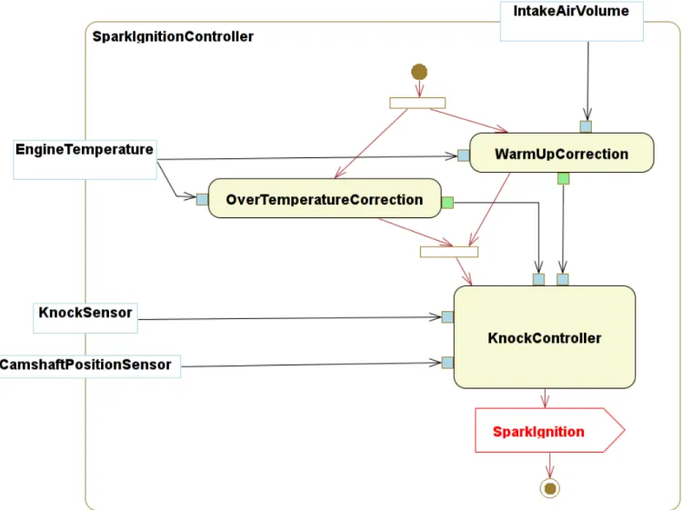
B. Functional Modeling of the example
The first functional model of the spark ignition control system is represented on Figure 1. It has been represented by an activity diagram made up with three main actions. The over temperature correction action computes the correction of the spark ignition relative to the engine temperature. The warm-up correction action computes the spark ignition correction mainly relevant when the engine is still warming up. Finally, the knock control correction action takes as inputs the two previous data and another one computed according to the pressure in the cylinder (provided by the so called knock sensor) and produces the spark ignition event.
The knock control function must be executed periodically (requirement 3) and data flow dependencies exists between the three actions. Periods associated with these functions are not measured on a classical chronometric clock such as the millisecond, but on clocks measuring the rotation speed of the engine (requirement 4) - i.e: the Camshaft and the Crankshaft clocks- which varies with the vehicle speed. The period value depends on the number of cylinders in the engine (requirement 4). In the same way, deadline or timing budget expressed either in milliseconds or camshaft degrees are associated with actions (requirement 5 and 6).
Fig. 1. Activity diagram for the knock
All these variants (number of cylinders, rotation speed) of the system should be considered in a process design flow. Final choices concerning these variants are settled during the design and/or the implementation phases. Nevertheless there is a need to
evaluate the feasibility/satisfaction of temporal requirements at an early stage of a design. Results obtained at the higher levels must be confirmed and refined at the lower levels. The refinement of these constraints and the integration of new elements in the design (hardware platforms, communication buses) allow a more accurate view of the system.
The early stage validation of requirements as well as the refinement of the system is presented in the next section. V. MARTE AND CCSL MODEL FOR MODELING ANIGNITIONCONTROLSYSTEM
A. Requirement modeling
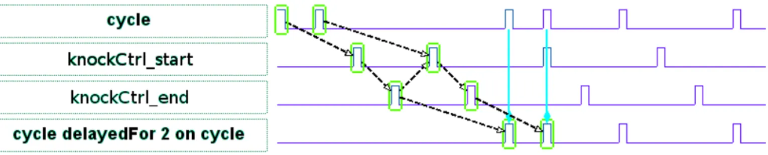
The first step is the formal specification of the requirements. Because requirements express constraints between the different events of the system, CCSL is well adapted to their formalization. For instance, if we consider the deadline expressed by the requirement 3 in section IV-A, it can be expressed by two precedence relations: the first between cycle instants that should precede the start of the knock control and the second between the end of the knock control and the cycle instants delayed by 2. Of course, it is obvious that the start of the knock control alternates with its end (it is a non reentrant routine). In CCSLit is specified by the three following constraints:
• cycle ≺ KnockCtrlstart;
• KnockCtrlend ≺ (cycle delayedFor2 oncycle); • KnockCtrlstart ∼ KnockCtrlend;
Even with only these preliminary requirements formally specified in CCSL, a simulation can be run in TIMESQUARE(see Fig 2). On the timing diagram, each clock is represented by a waveform. Concerning the constraints between clocks, the dashed arrows represent the partial ordering of clock instants and plain arrows stands for total instant ordering.
Fig. 2. A very first simulation resulting in a partial order of instants
ACCSLspecification can easily be extended by creating new clocks and adding new constraints corresponding to the others requirements, a new CCSL specification is obtained and a simulation can be run with TIMESQUARE. Such a simulation is important for two reasons. First, it detects inconsistencies in the requirements by creating a deadlock in the simulation (i.e., no solution can be found for this specification). Second, it provides timing diagrams of possible solutions of the requirements specification so that, requirement engineers can detect inconsistency in their requirements or, at the contrary, can become more confident with their design.
B. Functional modeling
After the requirement formalization, the next step is the modeling of the structural and behavioral view of the system. For instance, at this step an activity diagram like the one depicted in Fig.1 can be provided. Causalities between actions are provided by the diagram semantics (control flow of the activity diagram). They are specified in CCSL, by using precedences relation between ends and starts of actions (see the fifth line in table I). In our example, the start of the knock action must be preceded by the end of over temperature and warm up actions. A duration can also be attached to each action to represent an estimated temporal budget of the action. A simulation can then be used to ensure that the functional decomposition and the temporal budget are consistent with the requirements.
Additionally, the period and the offset of each decomposed action can be modeled by MARTE TimeValueSpecifications. This temporal information refers to different time bases such as the crkClk and the CamClk which are the two logical clocks characterizing the temporal evolutions of the engine.
Previous work with this level of refinement has already been done and the associated results are presented in [29]. It mainly highlights the possibility, at this level of refinement (requirement and functional model), to find inconsistencies in the specification of a system. In this paper, we go a step further since on one hand, we allow earlier detection of inconsistencies and on the second hand we refine the design to a very precise description of the system and its execution platform.
C. Task allocation and modeling in CCSL
While the functional model could be refined, we present here another aspect of the refinement, the choice of a task model for the functional model. The choice made here is simple, it allocates a task for each action described on Fig. 1.
A task is modeled by a start (T S) and a finish (T F) CCSL clock (c.f: line 1 in table I). We also add a “deadline” clock (T D), which represents the violation of the task deadline. Deadlines are specified in requirements and they are modeled as a timer expression in CCSL(c.f: line 4 in table I). A CCSLtimer starts synchronously with the start of the task (T S); it expires after de ticks of the reference clock (for instance crkClk). If the end of task (T F) occurs, the deadline timer is reset, otherwise, a T D tick is generated, indicating that the deadline is missed. Each task is also characterized by a duration d deduced from its associated action temporal budget(s). This specification is encoded in CCSL as specified on the third line in the table I: The finish clock is delayed from the start for a temporal distance d. Finally, the start clock can be characterized by a period p and an initial offset o. These values can be related to the requirements, for instance the knock control action, whose period is specified by the requirement 4 in section IV-A.
Element CCSLcode
Tasks ClockT S, T F , T D;
Period T SisPeriodicOnccperiodpoffseto; Execution duration T F = (T SdelayedFordoncc); Deadline timerConstraint(cc, T S, T F , T D, de); Task causal relations Tj S ≺ Tj F ;
TABLE I TASK MODELING WITH CCSL
At this stage it is also possible to simulate the temporal behavior of the model to check the consistency of the task allocation model. The simulation provides a first view of the scheduling of the tasks according to the different offsets, periods, deadlines and causalities.
D. Resource allocation and modeling in CCSL
We previously specified a system with infinite execution resources (i.e., a totally concurrent system). We propose here to represent the execution platform of the system. In this paper, we simply abstract the execution platform by a set of CPUs, however, more complex models with buses and their specific communication delays or with shared resources could also be considered. The allocation of the task model to an execution platform allows us to refine the system by considering preemption and delay due to tasks allocated on a single CPU.
Element CCSLcode
Resource ClockP ;
Allocation ∀ task i executing on P:ClockPi;
Exclusive use of
pro-cessor by tasks ∀ task i,j executing on P:Pi # Pj;
Duration / Allocation
on a processor T F = (T SdelayedFordonP ); the global clock cc
is the union of CPU clocks
∀ P n,P m in the system: cc = P nunionP m;
TABLE II
RESOURCES MODELING WITH CCSL
In our model, a CPU is associated to a millisecond time base labeled ms (i.e., one millisecond separates two consecutive CPU ticks). The execution duration of each task is measured on this time base. We chose to allocate the three tasks onto a single CPU. It implies a sharing of the CPU clock by the tasks. So, in the CCSLmodel, we defined three clocks PK, PW and PO that model the actual execution of each task on a CPU (Cf. line1 and 2 of table II). These clocks are then the time bases for the tasks. As a consequence, the execution duration d of a taski is measured on the clock Pi (Cf. line 4 of tableII). The Pi clock represents the CPU time allocated to taski. The CPU clock is then the union over its allocated tasks, of their Pi clock (Cf. line 5 of tableII). Moreover, because only one task can be executed at a time on a specific CPU, the Pi clocks of a single CPU are in exclusion each other.
E. Modeling multi clock systems
Since we want to model jointly the different time bases (crk and ms), we need to express the relation between them. CCSL
can also be used to express relationship between such clocks. In our example, the relation between a ms and a crk ˚ depends on the rotation speed of the Crankshaft (Rotation Per Minute). Equation 1 expresses this relation.
crk˚ = 1
6 ∗ RP Ms (1)
To translate this equation in CCSL, we have to consider a maximal bound for the RPM value (here fixed to 4500). Then, the translation on CCSL is the following:
• crkmin isPeriodicOnms period27; • crk ≺ crkmin;
F. Example specification and simulation
In order to simulate the system, aCCSLspecification has been written according to the rules specified in the previous sections. This specification gives a view of theCCSLconcrete syntax, has understood by the TIMESQUAREtool. In this specification we consider first the characteristics of each task i.e: its WCET on processor Pi (delayedFor) and its periodicity (TK is a periodic task with a period of 180 measured on the crk clock). Deadlines of each task is model with a timerConstraint. These deadlines are measured on the crk clock. The fourth part of the specification reflects the data dependencies between tasks execution. Part five models CPUs of each task and the global CPU clock ms. In the last part we solve the equation 1 which expresses the relationship between the crk clock and the ms clock, we fixed the motor speed to 1166 rpm (i.e., one crank degre every 7ms).
{
TK F = TK S delayedFor14onPK; TO F = TO SdelayedFor6 onPO; TW F = TW S delayedFor6onPW; TK SisPeriodicOncrk period180 offset6;
TKDuration =timerConstraintcrk,TK S,TK F,TK D,60; TODuration = timerConstraintcrk,TO S,TO F,TO D,50; TWDuration = timerConstraintcrk,TW S,TW F,TW D,50; TW F precedesTK S; TO F precedes TK S; TW S alternatesWithTK S; TO S alternatesWithTK S; PK #PO; PK #PW; PO #PW;
ms = (PK unionPW)unionPO; crk isPeriodicOnmsperiod7; }
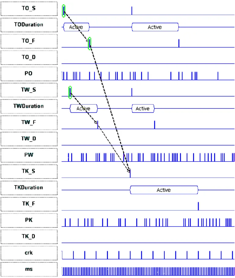
The previous CCSLspecification can be simulated in the TIMESQUARE environment.
In the case of the Ignition control system (ICS) example, we obtain the screen shot represented on Figure 3. Clock evolutions are represented by ticks. If we consider the knock task, on the figure we shows that as expressed in requirement 4, the tasks starts clocks (TK S) are periodic on clock crk. The rectangle in between a start (T S) and a finish (T F) tick represents a task execution. This execution depends on the availability of the resources (processor PO for the task Over temperature). The execution duration is measured on the ms clock (duration for Over Temperature is 6 ms). The solution computed by the simulator shows that due to the initial offset and the precedence rules Warm-up and Over Temperature are computed before the knock control task (dashed arrows models the precedence rules between start and ends of tasks). With the initial parameters, no deadline is missed (T D clocks never ticks on this simulation.)
We ran multiple simulations with different timing parameters values. For instance, we tried to reduce the deadline value of the knock control action to get a deadlock in order to approximate its minimum value. Nevertheless, the simulation technique
cannot ensure that the specification is correct for all possible execution. To ensure this correctness, a prover or an exhaustive simulation must be conducted. This is the topic of the next section. The remainder of this section explain why such verification can be realized.
As explained in sections III and II, CCSL mixes synchronous and asynchronous relations. In the general case, the result a such a specification is a partial order. The possibility to describe such relations is very powerful since it allows a first lazy synchronized specification of the system (used for the requirements and the first steps of the functional model refinement). However, it leads to the specification of a possibly infinite set of solution so that verification is hopeless. As seen before, each additional constraint tends to reduce the number of partial order solutions. More precisely, depending on the constraint used in the specification, the system can, along the refinement, become totally synchronous. During scheduling, all actions end up referring to a single CPU clock. After this kind of refinement, the specification becomes synchronous. The main benefits of such an approach is the ability to translate the specification into a synchronous language tooled for verification; as presented in the next section.
G. Verifying a design with Esterel observers
To prove the absence of deadlocks we use the technique of observers widely used in synchronous programming [30]. An observer is a reactive program expressing a property to verify. The observer is put in parallel with the program and receives the same inputs from the environment. It takes also as input the outputs of the program. The unique output of the observer is a violation signal. The verification consists of checking that the observer never emits the violation signal. Analysis is provided by calculating reachability analysis onto the synchronous composition of the observer and the program.
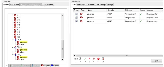
We used the notion of observer to verify that the requirements expressed inCCSL are correct and that deadlines of tasks are never missed. A systematic translation of CCSL rules into Esterel modules is provided by a dedicated plugin associated with TIMESQUARE1. This translation results in an Esterel program that encodes aCCSL specification as modules and the different observers. The Figure 4 shows the Esterel prover interface. On the left hand side is the list of observers which correspond to each CCSL expression and also signals corresponding to the tasks deadline (TK D, TO D and TW D). We want to check if these signals should be emitted (present) in the system. In that case it will mean that a deadline is missed.
On the right hand side of the figure are the results of the prover. After computation, the prover concludes the absence of these signals. This is the formal proof that the model, with these temporal parameters, task model and allocation model can never miss a deadline. This result conforms with the simulation we made with TIMESQUARE.
VI. CONCLUSION
In this paper we proposed an approach to specify and refine multi-clock real time systems. The approach is based on UML
for the structural and behavioral modeling and theMARTE OMGprofile for enrichingUMLmodels with multi-clock references. ThenCCSLis used to formally express causal and temporal constraints between the previously defined clocks. Because aCCSL
specification is a conjunction of constraints, refinement is obtained by the addition of constraints related to different design steps. At any steps, (from the requirement formalisation, to specification of the implementation) we can obtain an executable
CCSL specification, which integrates the different time base characteristics and constraints of the system.
By using the TIMESQUARE environment, it is possible to use the formal semantics ofCCSL to compute a partial order of clocks and visualize a correct execution if any. This execution can be for instance presented as a timing diagram. Consequently, it is possible, from the earlier steps of the design process, to detect inconsistencies in the choice of temporal and/or causal requirements. At the last step of the development, the specification encapsulates constraints from the requirements, the functional model, the task model, as well as the execution platform and its allocation to the task model.
In critical real time systems, a design should be proved correct with respect to the properties given for the observers. To that aim, starting from a synchronous CCSLspecification, we generate a corresponding Esterel program, which contains observers. It is then possible to run the Esterel studio prover to check that undesirable events can not occur (task deadline violations for instance). A design can then be proved to be correct.
Our approach is supported by tools such as thePAPYRUStool forUMLandMARTEmodeling, the TIMESQUAREenvironment for CCSL modeling and simulation and the TIMESQUAREobserver plugin to generate synchronous Esterel observers.
Future directions are already under investigation to pursue this work. First is the exploitation of TIMESQUARE execution traces to obtain accurate worst case response time for a specific task model. Another work in progress concerns the integration of different scheduling policies for tasks, directly as a plugin of the TIMESQUAREenvironment. Concerning the formal verification, because some few parts of the translation are still hand-made, we will investigate the full automation of the transformation between CCSL and an Esterel program.
ACKNOWLEDGMENT
The authors wish to thank the reviewers for their useful and valuable comments, which contributed to improve the quality of this paper.
REFERENCES
[1] The ATESST Consortium, “East-ADL2 specification,” ITEA, Tech. Rep., March 2008, http://www.atesst.org, 2008-03-20.
[2] The East-EEA Project, “Definition of language for automotive embedded electronic architecture approach,” ITEA, Tech. Rep., 2004, deliverable D.3.6. [3] The ATESST Consortium, “ATESST - the modelling approach: Overview of the East-ADL2,” ITEA, Tech. Rep., 2007, deliverable D.3.1. [Online].
Available: http://www.atesst.org
[4] AUTomotive Open System ARchitecture standard, Tech. Rep. [Online]. Available: http://www.autosar.org
[5] R. Wilhelm, J. Engblom, A. Ermedahl, N. Holsti et al., “The worst-case execution-time problem?overview of methods and survey of tools,” ACM Transactions on Embedded Computing Systems (TECS), vol. 7, no. 3, pp. 1–53, 2008.
[6] L. Sha, M. Klein, and J. Goodenough, “Rate monotonic analysis for real-time systems,” Foundations of Real-Time Computing: Scheduling and Resource Management, pp. 129–155, 1991.
[7] J. Stankovic, Deadline scheduling for real-time systems: EDF and related algorithms. Springer, 1998.
[8] D. Seto, J. Lehoczky, L. Sha, and K. Shin, “On task schedulability in real-time control systems,” in Real-Time Systems Symposium, 1996., 17th IEEE. IEEE, 2002, pp. 13–21.
[9] H. Espinoza, H. Dubois, S. G´erard, J. Medina, D. Petriu, and M. Woodside, “Annotating UML models with non-functional properties for quantitative analysis,” in Satellite Events at the MoDELS 2005 Conference. Springer, 2006, pp. 79–90.
[10] The ProMARTE Consortium, UML Profile for MARTE, beta 3, Object Management Group, May 2009, oMG document number: ptc/2009-05-13. [11] C. Andr´e, F. Mallet, and R. de Simone, “Modeling time(s),” in MoDELS, ser. Lecture Notes in Computer Science, G. Engels, B. Opdyke, D. C. Schmidt,
and F. Weil, Eds., vol. 4735. Springer, 2007, pp. 559–573.
[12] C. Andr´e, “Syntax and semantics of the clock constraint specication language,” INRIA, Tech. Rep. 6925, 2009.
[13] F. Mallet, C. Andr´e, and R. de Simone, “CCSL: specifying clock constraints with UML/Marte,” ISSE, vol. 4, no. 3, pp. 309–314, 2008.
[14] J. DeAntoni, F. Mallet, and C. Andr´e, “TimeSquare: on the formal execution of UML and DSL models,” Tool session of the 4th Model driven development for distributed real time systems, 2008.
[15] O. SEI, “An extensible source AADL tool environment,” SEI AADL Team technical Report, 2004.
[16] OMG, Systems Modeling Language (SysML) Specification 1.1, Object Management Group, May 2008, oMG document number: ptc/08-05-17. [17] P. Cuenot, P. Frey, R. Johansson, H. Lonn, M. Reiser, D. Servat, R. Koligari, and D. Chen, “Developing automotive products using the EAST-ADL2,
and Autosar compliant architecture description language,” in Embedded Real-Time Software Conference, Toulouse, France, 2008.
[18] F. Singhoff, J. Legrand, L. Nana, and L. Marc´e, “Scheduling and memory requirements analysis with AADL,” ACM SIGAda Ada Letters, vol. 25, no. 4, pp. 1–10, 2005.
[19] J. Stankovic, “Vest: A toolset for constructing and analyzing component based operating systems for embedded and real-time systems,” in Proceedings of the Embedded Software, First International Workshop (EMSOFT 2001), vol. 2211. Citeseer, pp. 390–402.
[20] I. T. project, Tech. Rep. [Online]. Available: www.timmo.org
[21] H. Blom, R. Johansson, and H. Lonn, “Annotation with Timing Constraints in the Context of EAST-ADL2 and AUTOSAR–the Timing Augmented Description Language.”
[22] K. Klobedanz, C. Kuznik, A. Thuy, and W. Mueller, “Timing modeling and analysis for AUTOSAR-based software development-a case study,” in Design, Automation & Test in Europe Conference & Exhibition (DATE), 2010. IEEE, 2010, pp. 642–645.
[23] A. Hamann, R. Henia, M. Jersak, R. Racu, K. Richter, and R. Ernst, “Symta/s-symbolic timing analysis for systems,” in WIP Proc. Euromicro Conference on Real-Time Systems 2004 (ECRTS’04). Citeseer, pp. 17–20.
[24] L. Lamport, “Time, clocks, and the ordering of events in a distributed system,” Communications of the ACM, vol. 21, no. 7, pp. 558–565, 1978. [25] C. Fidge, “Logical time in distributed computing systems,” Computer, vol. 24, no. 8, pp. 28–33, 2002.
[26] A. Benveniste, P. Le Guernic, and C. Jacquemot, “Synchronous programming with events and relations: the SIGNAL language and its semantics,” Sci. Comput. Program., vol. 16, no. 2, pp. 103–149, 1991.
[27] G. Berry, “The foundations of Esterel,” Proof, Language and Interaction: Essays in Honour of Robin Milner, pp. 425–454, 2000. [28] F. Boussinot and R. De Simone, “The ESTEREL language,” Proceedings of the IEEE, vol. 79, no. 9, pp. 1293–1304, 2002. [29] F. Mallet, M.-A. Peraldi-Frati, and C. Andr´e, “Marte CCSL to execute East-ADL timing requirements,” pp. 249–253.
[30] N. Halbwachs, F. Lagnier, and P. Raymond, “Synchronous observers and the verification of reactive systems,” in AMAST ’93: Proceedings of the Third International Conference on Methodology and Software Technology. London, UK: Springer-Verlag, 1994, pp. 83–96.