HAL Id: hal-01008084
https://hal.archives-ouvertes.fr/hal-01008084
Submitted on 27 Apr 2021
HAL is a multi-disciplinary open access
archive for the deposit and dissemination of
sci-entific research documents, whether they are
pub-lished or not. The documents may come from
teaching and research institutions in France or
L’archive ouverte pluridisciplinaire HAL, est
destinée au dépôt et à la diffusion de documents
scientifiques de niveau recherche, publiés ou non,
émanant des établissements d’enseignement et de
recherche français ou étrangers, des laboratoires
Dynamic compressive testing under confining pressure
on a quasi-brittle material
I. Masson, Pierrick Guégan, A.S. Lesaffre, Y. Quirion, Arnaud Poitou
To cite this version:
I. Masson, Pierrick Guégan, A.S. Lesaffre, Y. Quirion, Arnaud Poitou. Dynamic compressive testing
under confining pressure on a quasi-brittle material. EURODYMAT 2006 - 8th International
Confer-ence on Mehanical and Physical Behaviour of Materials under Dynamic Loading, 2006, Dijon, France.
pp.706-712, �10.1051/jp4:2006134109�. �hal-01008084�
Dynamic compressive testing under confining pressure
on a quasi-brittle material
I. Masson
1, P. Guegan
1, A.S. Lesaffre
2, Y. Quirion
2and A. Poitou
11École Centrale de Nantes, GeM (UMR CNRS 6183), 44321 Nantes Cedex 3, France 2CEA Le Ripault, 37260 Monts, France
Abstract. A testing device has been developed to study the dynamic compressive behaviour of a quasi-brittle
material under confining pressure. At the opposite of similar studies conducted with SHPB tests, this one is achieved with a crossbow system. This direct impact device is composed of a hurled mass and a measuring output bar. Moreover, a specific confinement system is developed. The specimen is confined laterally by a thin metallic sleeve and axially between two metallic plugs [1, 2]. A metallic part gathers the confining cell and the output bar together, and guides the whole during compression. High-speed camera is used to follow the cell compression, and an image post-treatment is realised. The axial strain is consequently obtained from the displacement between the input and the output plugs. In addition, the confining pressure is calculated using the ring expansion and the material constitutive law. Finally, strain gauges on the output bar are used to determine specimen axial stress. Different projectile masses, specimen diameters and ring thicknesses were tested in order to get specimen strain up to failure associated for different constant confinements. Finally, the device allows obtaining different strain rates with various confining pressures.
1. INTRODUCTION
For an application on a charged polymeric specific material, the CEA Le Ripault and the Ecole Centrale Nantes studied the realisation of a dynamic compressive test on cylindrical specimen, with high-pressure confinement, allowing the measurement of stress and strains in the material. Firstly, a bibliographic investigation allowed a global view on the subject. The major part of works concerns tests with SHPB setup, applied on several materials (steels, ceramics, PMMA). The material is confined by a metallic sleeve between two instrumented bars [1-7] (figure 1).
The sleeve is defined for to stay elastic during the test [2, 4], or to be plastic. Chen and Ravichandran [1, 3] use a plastic metallic sleeve on a ceramic test specimen. For the assembly, the specimen is cooled and the sleeve heated. This operation causes a confinement pressure, function of sleeve material and thickness, and relative diameter dimension. They determine this pressure by considering elastic law for the test specimen, and elasto-plastic perfect for the sleeve. They also considered a thin sleeve thickness in front of the ray of the test specimen in order to simplify their expressions.
Figure 1.(a) Schematic of a SHPB setup with confinement for testing syntactic foam. (b) A close-up view of the confining setup [7].
2. EXPERIMENTAL METHOD
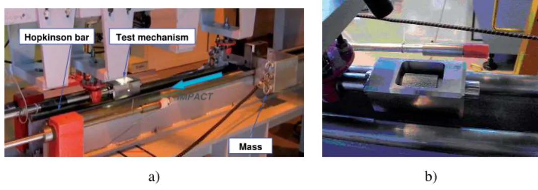
Based on these studies, we conceive a test on crossbow system [8], including a possibility of strain measurement by correlated pictures of a thin metallic sleeve during the test. The energy is produced by the impact of a 44 kg mass, moving at a speed of 4.8 m/s on a test mechanism (figure 2), which is mounted on a Hopkinson bar. The test specimen, included in the test mechanism, is quasi-instantaneous compressed. The Hopkinson bar gives a clean axial force expression before the wave returns.
The test specimen is into a metallic sleeve, between two plugs, guided in a test mechanism body (figure 3). The length sleeve must be higher than the specimen test in order to allow the installation of metallic plugs on both sides of the specimen test. This precaution makes it possible to apply the loading only to the plugs, which ensures a better confinement. In fact, if the compression is carried out on the sleeve and the test specimen, it is likely to have a relaxation of the confinement. Moreover, the plugs diameter must be slightly lower than the sleeve diameter, in order to limit friction between these two parts.
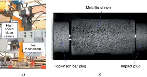
A high speed video camera films the sleeve and the two metallic plugs during the test (speed: 8000 p/s, resolution: 512 × 256 pix.) (figure 4).
Before tests, the observed surfaces of both the metallic sleeve and the plugs, are previously prepared in depositing of randomly painted points (black on a white zone), in order to make a post-treatment by correlated pictures analysis. The pictures are analysed with specific software (ICASOFT from INSA Lyon) to determine displacements of plugs and strains in sleeve. Complementary, a gauge on the opposite surface gives a comparative information of radial strain in the middle of the sleeve.
Hopkinson bar
IMPACT
Mass Test mechanism
a) b)
Figure 2. a) Test mechanism on crossbow system. b) Detail of test mechanism.
IMPACT Test mechanism body
Hopkinson bar plug
Metallic sleeve
Specimen test Impact plug Camera window
Test mechanism High speed video camera
Hopkinson bar plug
Metallic sleeve
Impact plug
a) b)
Figure 4.a) High speed video camera on crossbow system. b) Picture of sleeve and plugs by camera.
3. PARAMETERS 3.1 Sleeve material
We chose the 2017 aluminium alloy for the material sleeve. After some initial experimental investigations, we chose to simply assembly the test specimen in the sleeve without initial confinement pressure and with silicone lubricant. In fact, these parameters didn’t significantly affect the measured forces. The elasto-plastic constitutive relation is necessary to control the confined pressure during the test. For 2017 aluminium alloy, this law is approximated by a two slopes model as depicted on figure 5.
3.2 Sleeve and specimen dimensions
The specimen test diameter and length are respectively D = 20 mm and L = 20 mm. The internal sleeve diameter is 0.02 mm upper than the specimen test diameter. The length sleeve is 40 mm and its thickness is e = 1.7 mm. R0,2=240 Rm=380 σ (MPa) ε e=0.34% A%=10% O A B C E=70GPa ε (%)
For OA segment :σσσσ(MPa) = 70000.εεεε [1] For AB segment :σσσσ(MPa) = 1378.εεεε+ 235 [2]
4. RESULTS AND DISCUSSIONS 4.1 Video observation
The video recording shows a radial strain of the sleeve (figures 6a and 6b).
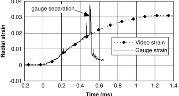
Using correlated pictures analysis allows for the radial strain field measurement on the observed surface (figure 6c). Because the observed surface is curved, the radial strain evolution moves in the space and its distance from the focal point of the camera evolves. For this test, knowing the relative position of the camera with respect to the sleeve, we could estimate that the maximum alteration of the radial strain on the middle of the sleeve was about 0.2 %.
For the most severe test, the maximal radial strain that we measured was about 6.5% on the middle of the sleeve surface. However, this final result has been confirmed by a direct measurement after test of the length variation of the specimen with a Palmer. The comparison between the video results and the radial strain measurement was also carried out by gauge glued in the middle of the sleeve that showed a very appreciable similarity (figure 7). Moreover, the video gives an expression of the radial strain after the rupture or separation of the gauge, and an expression of the strain field on all the observed surface, not only on a local zone like with the gauge.
Radial dilatation
2
a) b) c)
Figure 6. a) Sleeve before test. b) Sleeve during test. C) Radial strain of sleeve after correlated pictures analysis.
-0.01 0 0.01 0.02 0.03 0.04 -0.2 0 0.2 0.4 0.6 0.8 1 1.2 1.4 Time (ms) Radial strain Video strain Gauge strain gauge separation
Figure 7. Comparison between gauge and video radial strain in the middle of the sleeve surface.
4.2 Radial stress and pressure confinement
The relation [1] and [2] give the formulation of the elasto-plastic law of the sleeve material. By considering the sleeve as a thin tube, a simplified hydrostatic calculation determines the confinement pressure “p” applied to the test specimen (figure 8).
Thus, the radial stress, obtained with the radial deformation of the ring, yields to the confinement pressure (figure 9).
a)
b)
L
D
p
F
=
⋅
⋅
[3]
D
e
p
=
2
⋅
⋅
rad[4]
L e D e p p e F/2 F/2 rad σFigure 8.a) Distribution in sleeve. b) Formulation of radial force F and confinement pressure p.
0 10 20 30 40 50 60 0 1 2 3 4 5 6 Radial strain (%)
Confining pressure (MPa)
Confining pressure p
Figure 9.Confining pressure vs radial strain.
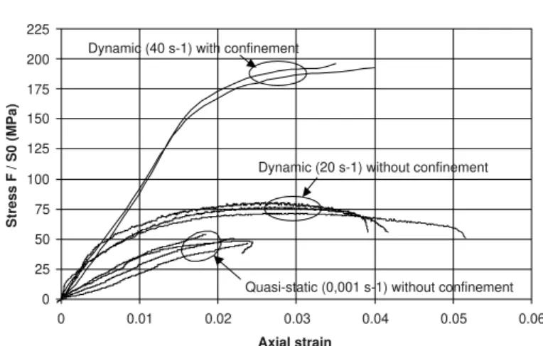
0 25 50 75 100 125 150 175 200 225 0 0.01 0.02 0.03 0.04 0.05 0.06 Axial strain Stress F / S0 (MPa)
Quasi-static (0,001 s-1) without confinement Dynamic (20 s-1) without confinement Dynamic (40 s-1) with confinement
Figure 10.Compressive stress vs axial strain for test dynamic and quasi-static tests, with and without confining pressure.
4.3 Axial stress comparison
This test shows that the material resists to a more severe axial loading when subjected simultaneously to a radial confinement pressure. In fact, an initial study without confinement showed a dynamical compressive rupture stress of 75 MPa (45 MPa in quasi-static), against 195 MPa with confinement (figure 10).
5. CONCLUSION
We tried to show in this study that a “triaxial” dynamic test was possible, in which a direct strain fields measurement of the sleeve was carried out by image correlation. This kind of measurement enriches the classical tests carried out by Chen [1, 3] or Gary [2] among others. It could therefore allow for a better dynamic characterization of friction for granular like materials.
References
[1] W. Chen and G. Ravichandran, Dynamic compressive failure of a glass ceramic under lateral confinement, J. Mech. Phys. Solids, 1997, Vol 45, n˚8, pp. 1303-1328.
[2] G. Gary, P. Bailly and F. Gatuingt, Testing concrete at high strains and high rates of strain, 3d Int. Symp. on Impact Engng, Singapour, 1999, Oxford University Press.
[3] Chen W. and Ravichandran G., An experimental technique for imposing dynamic multiaxial-compression with mechanical confinement, Experimental Mechanics, June 1996.
[4] Burlion N., Gary G. et Gatuingt F., Comportement expérimental en compaction statique et dynamique du micro-béton MB50 : Réseau de Laboratoires GEO (Géomatériaux Environnement Ouvrages), responsable du projet : P.Bailly, LEES ENSI de Bourges, 1999.
[5] Nemat-Nasser S., Dynamic response, residual strength, and high strain-rate failure modes of rock and concrete, Final Technical Report 1996-1999 to University of California, San Diego, by Air Force Office of Scientific Research.
[6] Huang C. and Subbash G., Influence of lateral confinement on dynamic damage evolution during uniaxial compressive response of brittle solids, Journal of the Mechanics and Physics of Solids, 2003, 51, 1089-1105.
[7] Song B., Chen W., Yanagita T. and Frew D.J., Confinement effects on the dynamic compressive properties of an epoxy syntactic foam, Composite Structures, 2004.
[8] Hamdan S. and Swallowe G.M., A crossbow system for high-strain-rate mechanical testing, Meas. Sci. Technol., 1996, 7, 1068-1072.