HAL Id: hal-00343624
https://hal.archives-ouvertes.fr/hal-00343624
Submitted on 2 Dec 2008
HAL is a multi-disciplinary open access archive for the deposit and dissemination of sci-entific research documents, whether they are pub-lished or not. The documents may come from teaching and research institutions in France or abroad, or from public or private research centers.
L’archive ouverte pluridisciplinaire HAL, est destinée au dépôt et à la diffusion de documents scientifiques de niveau recherche, publiés ou non, émanant des établissements d’enseignement et de recherche français ou étrangers, des laboratoires publics ou privés.
Naïs Coq, Olivia Du Roure, Marc Fermigier, Denis Bartolo
To cite this version:
Naïs Coq, Olivia Du Roure, Marc Fermigier, Denis Bartolo. Helical beating of actuated elastic fila-ment. Journal of Physics: Condensed Matter, IOP Publishing, 2009, sous presse. �hal-00343624�
Naïs Coq, Olivia du Roure, Marc Fermigier and Denis Bartolo
PMMH ESPCI-ParisTech-CNRS UMR 7636-Université Pierre et Marie Curie-Université Denis Diderot,10 rue Vauquelin 75231 Paris cedex 05 France. E-mail: [email protected]
Abstract. A possible propulsion mechanism at low Reynolds number is the rotation of a flexible filament, tilted with respect to its rotation axis. Using a simple linear model, we establish the non linear torque-force relations for two torque-driven actuation modes. When the rotation of the filament is induced by two perpendicular transverse oscillating torques, the propulsive force increases monotonically with the torque amplitude. However, when a constant torque directed along the rotation axis is applied to the filament, an unstable branch appears in the torque-force characteristics, leading to a discontinuous transition in the shape of the filament. We characterize this shape transition using two geometrical parameters, quantifying the wrapping around and the collapse on the axis of the filament, both experimentally and theoretically.
PACS numbers: 2008, 2008
1. Introduction
The oscillations of flexible flagella and the rotation of "rigid" chiral arms are the two most standard propulsion strategies used by microorganisms [1]. The hydrodynamics of these two modes of locomotion have been extensively studied in the past, both theoretically and experimentally, see e.g. [2, 3] and references therein. Recently, Dreyfus et al. have even succeeded in fabricating the first man-made microswimmer, relying on the magnetic actuation of an artificial flagellum, made of self-assembled paramagnetic colloids [4]. Conversely, the design of chiral propelling microstructures remains a technical challenge. A possible solution to this problem could be the use of soft rotating filaments, which spontaneously adopt chiral shapes.
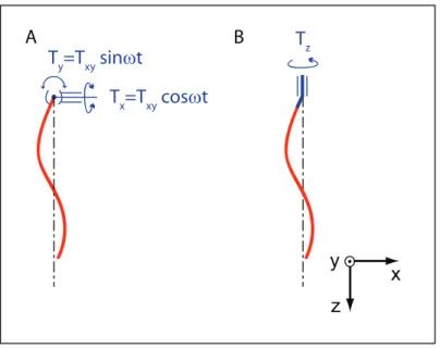
In this paper, we focus on this intermediate propulsion mechanism, which has raised much interest in the last two years and motivated a set of theoretical and numerical works [5, 6, 7, 8]. Firstly, on the basis of a simple linear model, we establish the non linear constitutive relations between the propulsive force and the actuation torques. We expose important qualitative differences between two beating modes in torque-driven systems. The propulsive force increases monotonically with the torque amplitude in the case of two transverse torques applied perpendicularly on the filament, figure 1a. Oppositely, elastic filaments actuated by a constant longitudinal torque, figure 1b, exhibit an unstable branch in the force-torque relation, which can lead to a strong discontinuity in the propulsion force when the rotation period becomes of the order of the largest relaxation time of the bending modes.
Secondly, we present the results of an experiment performed with a macroscopic flexible filament immersed in a viscous fluid. Force and torque measurements are in excellent agreement with our simple model. Furthermore, our observations allow us to relate the strong non linearities in the force response to a wrapping transition in the shape of the filament.
2. Force-torque constitutive relations for a rotating flexible filament 2.1. Beating of flexible rods: a minimal model
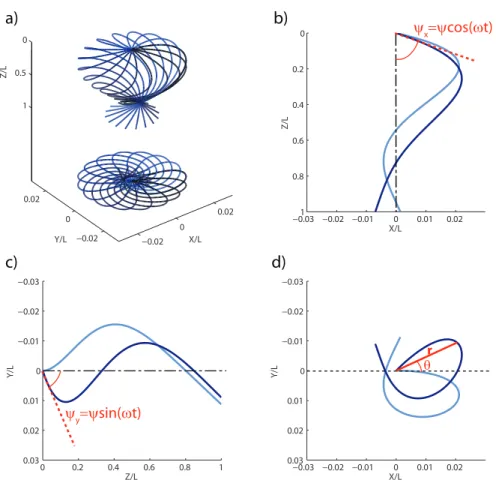
The beating of flexible rods in viscous flows has proven to be accurately described by simple models ignoring geometrical non linearities and non local hydrodynamic effects [9, 10]. We here restrain our analysis to this framework. More precisely, we consider a flexible rod initially straight and oriented with an angle ψ with respect to the rotation axis z. The rotation of the filament is imposed at one of its extremities (z = 0), while the other end remains free (z = L), figure 2. The external torques applied at the anchoring point impose the rotation of the tangent vector: t(0, t) = [ψ cos(ωt), ψ sin(ωt), 1]. As a result of the competition between viscous and elastic forces, the filament adopts a curved shape: r = [x(z), y(z), z] parametrized by the z coordinate. Within the small deformations approximation the bending energy of the rod is a quadratic functional of its local curvature |∂2
Tz x y z Tx=Txy cosωt Ty=Txy sinωt A B
Figure 1. A: Sketch of a flexible filament actuated by two A.C. transverse perpendicular torques oriented along the x and y axis. B: Sketch of the same filament actuated by a D.C. axial torque oriented along the z axis.
local elastic force being: fel = −κ∂z4r. The coupling with the surrounding viscous fluid
is modelled by a local anisotropic friction coefficient (resistive force theory). The local viscous drag is defined by:
fv= (ηk− η⊥)(t.v)t + η⊥v, (1)
where v is the material velocity, ηk and η⊥ are the longitudinal and transverse drag
coefficients respectively. For slender rods with a circular cross section the coefficients are well approximated by η⊥ = 4πη/ h log(L/a) +1 2 i and ηk = 2πη/ h log(L/a) − 1 2 i , where a is the radius of the rod and η is the viscosity of the fluid [11]. In the small deformations approximation, the force balance equation fe+ fv = 0 reduces to the so-called Machin
equation [12]:
η⊥∂tr = −κ∂z4r. (2)
After a spatial Fourier transform, this equation is readily solved. The rod undergoes a rigid body rotation at angular frequency ω as a result of the superposition of four propagating bending waves damped over a distance lω ≡ (κ/η⊥ω)1/4. Defining the four
complex wave numbers: qn = lω−1exp
h
i(nπ4 − π4)i, the rod profile is given by: x(z, t) = (ψL) ℜ 4 X n=1 αne[iωt−qn(ω)z] ! , (3) y(z, t) = (ψL) ℑ 4 X n=1 αne[iωt−qn(ω)z] ! . (4)
The αn coefficients are set by the boundary conditions: r(0) = 0 (fixed end), ∂z(t) =
t(0, t) (angular actuation), ∂3
zr(L) (force free end) and ∂z2r(L) (torque free end). A
0 0.5 1 1.5 2 X/L Y/L Z/L −0.03 −0.02 −0.01 0 0.01 0.02 0 0.2 0.4 0.6 0.8 1 X/L Z/L 0 0.2 0.4 0.6 0.8 1 −0.03 −0.02 −0.01 0 0.01 0.02 0.03 Z/L Y/L −0.03 −0.02 −0.01 0 0.01 0.02 −0.03 −0.02 −0.01 0 0.01 0.02 0.03 X/L Y/L ψx=ψcos(ωt) 0 0.02 0 0.02 −0.02 −0.02 ψy=ψsin(ωt) r θ c) d) a) b)
Figure 2. Shape of an elastic filament driven at z = 0 for lω/L = 0.18 and ψ = 15◦.
(a) Thirty snapshots of the filament profile over one rotation period. Below are their projections in the (x, y) plane. The time interval between each snapshot is constant. (b), (c) and (d): Projection of the same two profiles in the (x, z), (y, z) and (x, y) planes respectively, taken at two different times. Note that the filament undergoes a rigid body rotation although the projected shapes in the (x, z) and (y, z) planes are time-dependant.
2.2. Propulsive force:
We now focus on the propulsive properties of the filament. As the viscous flow bends the filament into a chiral shape, a non zero thrust is generated along the z axis. The anchoring point experiences an axial force Fz = ez ·R fv(z) dz, with fv as defined in
Eq. 1. In all that follows, the forces are normalized by the elastic force necessary to bend the filament with a curvature of order 1/L: Fe ≡ κ/L2. We also normalize the
rotation speed by the inverse of the viscous relaxation time of the bending mode of wavelength L, τ = η⊥L4/κ. The resulting dimensionless number Sp ≡ ωη⊥L4/κ is
commonly referred to as the Sperm number in the context of low Reynolds number locomotion; it may also be convenient to express Sp in terms of penetration length:
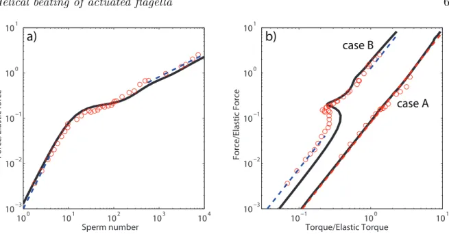
Sp = (L/lω)4. The variations of the normalized axial force with the Sperm number are
shown in figure 3a. The axial force increases monotonically with the Sperm number; this increase is rather fast in the low Sp regime whereas it weakens for large Sp. To account for these variations, we stress that both the three-dimensional shape of the rotating filament and the axial force Fz are identical to those obtained by the superposition of
two filaments beating periodically in perpendicular planes. Indeed, using Eqs. 2 and the boundary conditions at the filament ends, one can easily provide a local expression for Fz = κPu=x,y
h
∂zu(0)∂z3u(0) − 12∂z2u2(z)
i
, which is a well-known result in the context of planar oscillations [9]. It yields a thrust increasing quadratically with the beating pulsation ω in the low frequency limit. It is worth mentioning that this scaling law can also be predicted from a symmetry argument. At low Reynolds number, a rotating chiral object experiences a viscous force Fz = Mω, where M is a coefficient of the so-called
mobility matrix [13]. M is zero for a non chiral object; since at ω = 0 the filament is straight, M(ω = 0) must vanish. Moreover, changing the sign of the rotation changes the chirality of the filament, which implies that M is an odd function of ω. Hence, in the low speed limit, we expect M to increase linearly with the angular velocity leading to an overall force proportional to ω2. It follows that F
z ∼ FeSp2 from dimensional
analysis. Note that this implies that the sign of the force is independent of the sense of rotation.
In the high Sp limit, the filament is strongly deformed. The chiral deformations are localized in a region of extent lω ≪ L in the vicinity of the anchoring point. For z > lω
the bending waves in both the (x, z) and (y, z) planes are damped and the filament has collapsed on the rotation axis. The force produced by the wrapped filament is comparable to the one induced by the rotation of a rigid helix of length, pitch and radius lω, which increases like ωl2ω. It then follows from dimensional analysis that
Fz ∼ FeSp1/2 in this high Sp limit. Note that this last scaling argument holds beyond
the small deformations approximation.
2.3. Torque controlled actuation: discontinuous dynamic transition
We have here characterized the propulsive force corresponding to a given beating pulsation, independently of the actuation mechanism at the rod end. We now investigate two specific forcings where imposed external torques drive the filament. We show that major differences arise in the force-torque constitutive relation as well as in the filament kinematics.
The two actuations modes we consider (referred to here as A and B) are sketched in figure 1. Case A: The rotation of the tangent vector at the anchoring point around the z axis results from the simultaneous periodic oscillations of two transverse torques (Tx and Ty) aligned along the x and y axis, see figure 1a. For sake of simplicity we only
consider the case where the two torques have the same amplitude and a π/2 phase shift: Tx = Txycos(ωt) and Ty = Txysin(ωt). Tx and Ty alone would induce the propagation of
100 101 102 103 104 10−3 10−2 10−1 100 101 Forc e/Elastic force Sperm number 10−1 100 101 10−3 10−2 10−1 100 101 Torque/Elastic Torque Forc e/Elastic For ce
a)
b)
case A case BFigure 3. (a) Propulsive force normalized by the elastic force as a function of Sp. Solid line: theoretical prediction from the linear model. Dashed lines: asymptotic scaling behaviors: Sp2
and Sp1/2 in the low and high Sp limits respectively. Circles:
experimental data. (b) Normalized propulsive force Fz/Feversus normalized transverse
torque Txy/Te(case A) and versus normalized axial torque Tz/Te(case B). Solid lines:
theoretical predictions from the linear model. Dashed line for case A: quadratic power law. Dashed lines for case B: asymptotic scaling behaviors: Sp2
in both the low and high Sp limits. Circles: experimental data.
torque Tz in the z direction applied to a crankshaft which sets the angle between the
tangent vector and the rotation axis, see figure 1b.
Whatever the actuation mode, the external torque applied on the filament balances the local viscous torque integrated along the filament:
T= −
Z
r× fvdz, (5)
where the viscous force is defined in Eq. 1. We now establish the constitutive relations between the propulsive force Fz and the external torque amplitudes parametrized by the
angular velocity ω. More precisely, we computed the torques Txy(ω) or Tz(ω) required
to rotate the filament at a given ω, knowing the filament shape from Eqs. 3 and 4 and using Eqs. 1 and 5.
Before entering into a more detailed description, we can anticipate the asymptotic behaviors common to the two actuation modes. In the low Sp (low speed) limit the filament is barely deformed. The torque T is then simply the one needed to rotate a tilted rigid rod in a viscous fluid and both Txy and Tz scale as η⊥ωL3 ∼ Sp. In
the other limit, large Sp, only a portion of length lω deviates from the z axis, on a
distance of order lω as well, and contributes to the viscous torque. As a consequence the
rigid body rotation of such filaments collapsed on the z-axis induces torques of typical amplitude η⊥ωl3ω ∼ Sp1/4 in the three directions. Combining these predictions with the
imposed torque amplitude whatever the actuation mode (A or B) both in the small and large torques limits: Fz ∼ Txy2 for case A, and Fz ∼ Tz2 for case B. However, plotting
the full constitutive relations, we uncover a major difference between the apparently similar actuation mechanisms, figure 3b. Again, torques are systematically normalized by the elastic torque Te= κ/L. Case A: As expected the axial force is a monotonically
increasing function of Txy as in the case of a 2D beating. More surprisingly the
constitutive relation is very well approximated by a single quadratic function for all Sp. Case B: Oppositely, this second actuation mode reveals a counter intuitive response to the axial torque. Indeed for intermediate torques (corresponding to intermediate sperm numbers) Fz decreases with Tz. This decreasing branch is unstable and would
lead in practice to hysteretic jumps in the axial force upon torque cycling. This result is in good agreement with the molecular dynamics simulations of Manghi et al. [5]. We wish to underline that this phenomena is intrinsically related to the non-linear interplay between the linear elasticity and the linear viscous flow. In the case of rotating rigid chiral structures the linearity of the Stokes equation implies that the axial force should increase linearly with the applied torque whatever the details of the objects shapes.
Two physical comments should be made at this point: firstly, the overall quadratic increase of the force with the actuation torque means that the range of available forces is wider when the chirality of the rotating body is induced by the fluid-structure
interaction. We indeed recall that the thrust generated by a rigid helix is only
proportional to the applied torque. Secondly, it follows from the constitutive relations that these two actuation modes obviously offer very different propulsion strategies. The A mode, which requires two independent rotational actuators, provides very robust forces with respect to the torque fluctuations. Conversely, to vary its propulsive force over a wide dynamical range, a swimmer using a B-type actuation only needs slights modulations of its control torque.
3. Experiments: Shape and force transitions
To better understand the counter intuitive response of the elastic filament to an external axial torque (case B), we performed a rotation speed-controlled experiment on macroscopic flexible filaments. Firstly, our measurements allowed us to assess the validity of the predictions in the presence of long-range hydrodynamic coupling and geometrical non linearities. Secondly, the quantitative characterization of the observed filament profiles shed some light on the geometrical origins of the discontinuity in the torque-force relation.
3.1. Experimental setup
We used elastomeric filaments attached to an electric motor, immersed in pure glycerin. The filaments were made by filling a glass capillary tube with a 1:1 mixture of polyvinylsiloxane polymer and curing agent. Iron carbonyl particles were added to the
polymer solution in order to match the density of the glycerin. The curing is thermally activated and occurs within minutes at room temperature. The glass capillary was then broken in order to retrieve an elastomeric rod of radius a = 435 µm, and of length L varying from 2 to 10 cm. Young’s modulus of the charged filament was measured by dynamical mechanical analysis: E = 0.7 Mpa. The filament was then immersed in the glycerin tank (measuring 20 ×20 ×20cm3). The shear viscosity η = 1 Pa.s was measured
with a controlled stress rheometer in a cone-plane geometry prior to each experiment, and exhibited no change due to pressure or hygroscopic variations. The motor, placed on top of the tank, could deliver discrete rotation speeds ranging from 0.01 to 10 rpm, through a gearbox, yielding Sperm numbers varying over five decades (from 10−1 to
104). The elastic filaments were attached to the motor axis, so as to be fully immersed
in the glycerin, with an angle ψ = 15◦ between the filament at rest and the vertical
rotation axis. The high viscosity of the fluid allowed us to remain in low Reynolds number conditions (Re < 10−2) throughout the range of lengths and speeds available.
The filament first goes through a transient regime, which lasts up to about 1h for the longest filament. It then reaches, as expected, a stationary shape which undergoes rigid-body rotation. We here focus our attention only on the steady-state regime. Typical pictures are displayed in figure 4. To obtain the experimental shapes, a mirror was positionned with a 45◦ angle from the side of the tank, allowing us to take pictures
of the filament projected simultaneously in two perpendicular planes with a single 6 MPixels digital camera (Nikon D70). We used a correlation algorithm to extract the coordinates from these pictures, thus determining the experimental profile with submillimeter precision.
3.2. Force and shape transitions
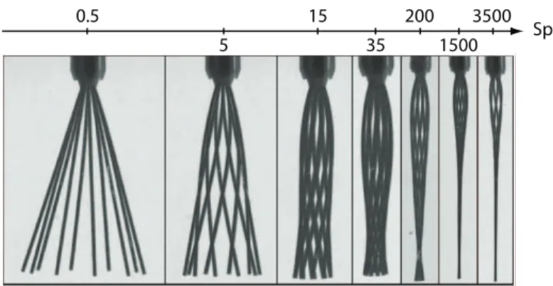
Sp 0.5 5 15 35 200 1500 3500
Figure 4. Evolution of the filament shape as a function of Sp. Each picture is a superposition of snapshots taken over one rotation period, with a constant time interval. As Sp increases, the filament wraps itself around and collapses on the rotation axis.
For all accessible Sperm numbers, we have computed the axial forces and torques Fz and Tz from quantitative image analysis, using Eqs. 1 and 5 and v(z) = ωr(z)eθ
for the local filament velocity. We compare in figures 3a and 3b our experimental measurements to the theoretical prediction for the variations of Fz and Tz with Sp.
Our crude model with no adjustable parameter proves to be in remarkable agreement
with the experimental data. This agreement demonstrates that neither the long
range hydrodynamic interactions nor a more accurate description of the geometry are required to capture the main features of the propulsive force-velocity and force-torque characteristics. In particular, the strong discontinuity in the force through the unstable branch was correctly accounted for. Note that Fz can experience an amplification by a
factor of two when Tz jumps to the second stable branch.
We now come to a more detailed description of the shape transition underlying this force-torque constitutive relation. As depicted in figure 4, for Sp < 10, the filaments remain almost straight. For intermediate Sperm numbers, Sp ∼ 10, the filament is increasingly bent by the viscous flow, and it continuously wraps itself around the axis of rotation as Sp increases. Finally, above Sp = 500 the rod has completely collapsed on the axis but for a small fraction of the filament, below the anchoring point, which keeps its helical shape. To better characterize the collapse and the wrapping of the filament on the z-axis, we display in figures 5 the evolution of the distance to the axis of the rod free end normalized by the rod length, δ = r(L)/L, and of the wrapping angle, δθ = θ(L) − θ(0) (see figure 2 for the definition of θ). δ decreases monotonically as Sp increases. At low Sperm numbers, the bending of the filament mostly occurs in the flow direction, and δ weakly deviates from sin ψ. This stems from the fact that only chiral rods can experience forces pointing towards the rotation axis when undergoing a rigid body rotation, due to the symmetries of the Stokes equation upon time and parity transformations. As a consequence, whereas the orthoradial deformations scale as Sp, the bending amplitude in the radial direction must scale as Sp2, which yields δ = sin ψ − O(Sp2) in the low
Sp limit. For large Sperm numbers, the bending waves propagating along the filament are damped exponentially. Thus δ also decays exponentially to zero. It is important to notice that the inflexion between these two asymptotic behaviors occurs at Sp = 20 which precisely corresponds to the onset of the unstable branch in the (Tz(Sp), Fz(Sp))
constitutive relation.
The wrapping around the rotation axis increases monotonically with Sp. In the low Sp limit, the linear variations of the orthoradial bending deformations yield a linear increase of ∆θ with Sp. Again, at Sp = 20, this linear variation crosses over to another power law regime. In this high Sp limit, we observe that δθ ∼ Sp1/4. In both asymptotic
regimes the wrapping angle is proportional to the axial torque Tz, which is typical
of the linear response of an elastic structure. What is definitely surprising is that at intermediate Sp, this linear relation is lost as the torque-angle characteristics displays an unstable branch.This is another manifestation of the unstable fluid-structure interplay. We show in figure 5c and 5d, the variations of δ and of δθ as a function of the axial torque. This allows us to quantify the amplitude of the discontinuous collapse and wrapping of the filament for a torque-driven experiment. When Tz exceeds the first
100 102 104 0 0.05 0.1 0.15 0.2 0.25 0.3 0.35 δ Sp 100 102 104 100 101 δθ Sp 10−1 100 0 0.05 0.1 0.15 0.2 0.25 0.3 δ Tz/Te 10−1 100 100 101 δθ Tz/Te c) d) a) b)
Figure 5. (a) Distance to the axis at the rod end, δ = r(L)/L, as a function of Sp. (b) Wrapping angle δθ as a function of Sp. (c) δ as a function of the normalized actuation torque Tz/Te. (d) δθ as a function of Tz/Te. Solid lines: theoretical prediction from
the linear model. Circles: experimental data. Dashed lines in (b): asymptotic scaling behaviors: δθ ∼ Sp and δθ ∼ Sp1/4 in the low and high Sp limits respectively. Dashed
lines in (d): asymptotic scaling behaviors: δθ ∼ T /Te in both low and high T /Te
limits. The difference between the theoretical and experimental data is due to a small experimental offset in the transverse direction : r(0) = 2mm [14].
is lowered by more than 75 percent. The variations of the wrapping angle are even more spectacular: the discontinuous winding of the filament corresponds to a jump of about 70◦ around the rotation axis.
4. Conclusion
In this paper, we have studied theoretically and experimentally the periodic motion of a flexible filament immersed in a viscous fluid. We paid special attention to the non linear force-torque relation resulting from the interplay between the linear elasticity of the rod and the also linear Stokes flow. We have shown that the characteristics of the propulsive force strongly depends on the actuation mode for a torque-driven beating.
In particular, in the case of an axial crankshafting actuation, we have identified and characterized a discontinuous transition in the filament shape resulting in a significant amplification/reduction of the propulsive force for minute variations of the imposed torque. This jump in the force would allow a microswimmer or a micropump to achieve strong accelerations without having to provide significant changes in the actuation mechanism.
This work has been partly supported by a DGA-CNRS fellowship (Naïs Coq). References
[1] D. Bray. Cell Movements. Garland Publishing, New York, NY, 2000.
[2] E. Lauga. Floppy swimming: Viscous locomotion of actuated elastica. Phys. Rev. E, 75:041916, 2007.
[3] J. Lighthill. Flagellar hydrodynamics - The John von Neumann lecture, 1975. SIAM Rev., 18:161– 230, 1976.
[4] R. Dreyfus, J. Baudry, M. L. Roper, M. Fermigier, H. A. Stone, and J. Bibette. Microscopic artificial swimmers. Nature, 437:862–865, 2005.
[5] M.Manghi, X. Schlagbergerand, and R. Netz. Propulsion with a rotating elastic nanorod. Phys. Rev. Lett, 96:068101, 2006.
[6] A. Vilfan and F. Jülicher. Hydrodynamic flow patterns and synchronization of beating cilia. Phys. Rev. Lett., 96:058102, 2006.
[7] B. Qian, T. Powers, and K. Breuer. Shape transition and propulsive force of an elastic rod rotating in a viscous fluid. Phys. Rev. Lett., 100:078101, 2008.
[8] N. Coq, O. du Roure, J. Marthelot, D. Bartolo, and M. Fermigier. Shape transition and propulsive force of an elastic rod rotating in a viscous fluid. Physics of Fluids, 20:051703, 2008.
[9] C. H. Wiggins and R. E. Goldstein. Flexive and propulsive dynamics of elastica at low Reynolds number. Phys. Rev. Lett., 80:3879 – 3882, 1998.
[10] T. S. Yu, E. Lauga, and A. E. Hosoï. Experimental investigation of elastic tail propulsion at low reynolds number. Physics of Fluids, 18:091701, 2006.
[11] G. K. Batchelor. Slender-body theory for particles of arbitrary cross-section in stokes flow. J. Fluid Mech., 44:419, 1970.
[12] K. E. Machin. Wave propagation along flagella. J. Exp. Biol., 35:796, 1958.
[13] J.-P. Hulin, E. Guyon, L. Petit, and C. D. Mitescu. Physical hydrodynamics. Oxford University Press, 2001.