HAL Id: hal-01660968
https://hal.archives-ouvertes.fr/hal-01660968
Submitted on 3 Jun 2021
HAL is a multi-disciplinary open access
archive for the deposit and dissemination of
sci-entific research documents, whether they are
pub-lished or not. The documents may come from
teaching and research institutions in France or
abroad, or from public or private research centers.
L’archive ouverte pluridisciplinaire HAL, est
destinée au dépôt et à la diffusion de documents
scientifiques de niveau recherche, publiés ou non,
émanant des établissements d’enseignement et de
recherche français ou étrangers, des laboratoires
publics ou privés.
Distributed under a Creative Commons Attribution| 4.0 International License
What Can We Learn in Electrocatalysis, from
Nanoparticulated Precious and/or Non-Precious
Catalytic Centers Interacting with Their Support?
Juan Mora-Hernández, Yun Luo, Nicolas Alonso-Vante
To cite this version:
Juan Mora-Hernández, Yun Luo, Nicolas Alonso-Vante. What Can We Learn in Electrocatalysis, from
Nanoparticulated Precious and/or Non-Precious Catalytic Centers Interacting with Their Support?.
Catalysts, MDPI, 2016, 6 (9), �10.3390/catal6090145�. �hal-01660968�
catalysts
ReviewWhat Can We Learn in Electrocatalysis,
from Nanoparticulated Precious and/or Non-Precious
Catalytic Centers Interacting with Their Support?
Juan Manuel Mora-Hernández, Yun Luo and Nicolas Alonso-Vante *IC2MP, UMR-CNRS 7285, University of Poitiers, 4 rue Michel Brunet, 86022 Poitiers, France; [email protected] (J.M.M.-H.); [email protected] (Y.L.)
* Correspondence: [email protected]; Tel.: +33-054-945-3625 Academic Editors: Vicenzo Baglio and David Sebastián
Received: 12 July 2016; Accepted: 9 September 2016; Published: 21 September 2016
Abstract: This review is devoted to discussing the state of the art in the relevant aspects of the synthesis of novel precious and non-precious electrocatalysts. It covers the production of Pt- and Pd-based electrocatalysts synthesized by the carbonyl chemical route, the synthesis description for the preparation of the most catalytically active transition metal chalcogenides, then the employment of free-surfactants synthesis routes to produce non-precious electrocatalysts. A compilation of the best precious electrocatalysts to perform the hydrogen oxidation reaction (HOR) is described; a section is devoted to the synthesis and electrocatalytic evaluation of non-precious materials which can be used to perform the HOR in alkaline medium. Apropos the oxygen reduction reaction (ORR), the synthesis and modification of the supports is also discussed as well, aiming at describing the state of the art to improve kinetics of low temperature fuel cell reactions via the hybridization process of the catalytic center with a variety of carbon-based, and ceramic-carbon supports. Last, but not least, the review covers the experimental half-cells results in a micro-fuel cell platform obtained in our laboratory, and by other workers, analyzing the history of the first micro-fuel cell systems and their tailoring throughout the time bestowing to the design and operating conditions.
Keywords:low temperature fuel cells; electrocatalysts; catalytic centers; micro laminar flow fuel cells
1. Introduction
Fuel cell technology is a promising strategy to provide power for areas where there is no access to the public or where the cost of wiring and electricity transfer network is important. These devices are usually employed as an energy source for purposes that require non-intermittent power stations such as power generation and energy distribution systems. The use of hydrogen as a fuel makes them clean energy systems with less noise, and pollution generation [1]. Currently, fuel cells are used in both small and large systems such as combined-heat-power (CHP) systems, mobile power, portable computers and communication equipment [2]. Despite all these advantages, there are some limitations for the use of fuel cells. For example, the short lifetime caused by impurities in the gas stream inlets, degradation and poisoning of the catalysts used as electrodes, slow kinetics to perform multi-electron charge transfer reactions, low density output power per unit volume and low accessibility are, to name a few, challenges to overcome. However, in the last years, a great progress in the development of this technology using novel catalysts and fuels aiming at optimizing the operation of fuel cells [2] has been made. Among the main fuel cells operation issues, we can find the high cost and availability of electrocatalysts, the degradation of the proton exchange polymeric membrane, and the oxygen reduction reaction (ORR) kinetics. This reaction takes place on the most active element, Pt, at an overpotential of around 0.3 to 0.4 V [3]. For this reason, fuel cells operate, in practice, at a much
lower potential relative to the theoretically possible and with a very low efficiency [4]. The ORR is, in fact, one of the most important reactions in electrochemistry because of its central action in metal-air batteries, electro-synthesis of hydrogen peroxide and the manufacture of cathodes for fuel cells [4]. The molecular oxygen reduction is ideally performed by a transfer mechanism of four electrons. A process involving a single step in which molecular oxygen is reduced to water [5]. Any new ORR electrocatalyst should be investigated to determine the ORR kinetics, since the H2O2produced often causes the degradation of the polymer electrolyte membrane in the heart of proton exchange cells [5]. Nowadays, an important variety of precious metals are used as ORR electrocatalysts.
Platinum supported on carbon is usually used as an anode to conduct the oxidation reaction of hydrogen (HOR) as well as at the ORR at the cathode. It is well stablished that Pt is costly and very sensitive to the presence of contaminants [6]. Numerous strategies have been explored to reduce the mass loading and improve its activity. One of these strategies is the formation of Pt-alloys with 3d transition metals. These kind of alloys can also inhibit the formation of adsorbed species such as hydroxyl, Pt-OH [7]. The transition metal alloys of Pt with, e.g., Ir, Ru, Rh, Re, Os, increase substantially the electrochemical activity, reduce the mass loading, induce lower overpotentials, and promote the reaction of four-e−[8]. A study carried out by Min et al. [9] considers that the electrochemical property of Pt and its alloys is a result of electronic factors. They suggested that the ORR kinetics increases with the decreasing vacancies in the 5d band of Pt, since such hybridization is less favorable as there is an increase in particle size, implying a decrease of the adsorption strength of the oxygen species. Mukerjee et al. [7] concluded that, on PtCo/C, PtCr/C, PtMn/C, PtFe/C, and PtNi/C alloys, the catalytic activity is increased by an electronic combination which produces changes in the vacancies of the d band, and alloy network contractions. Thus, better ORR properties were obtained on PtCr/C. Markovic et al. [10] reported the synthesis of two Pt-based materials; PtFe and PtCo nanowires. The PtFe electrocatalysts presented higher activity than PtCo toward the ORR due to a greater Co leaching from the alloy. The mass activity and specific surface of the PtFe nanowires were higher than the commercial platinum electrocatalyst. Besides the effect obtained by alloying with early or late transition metals, the electronic properties of Pt NPs can also be modulated by interaction with the support. Indeed, in recent years, exhaustive research activities have been conducted for searching active Pt structures to reach the Department of Energy (DOE) targets [11], which led to the development of many different types of alloys, often identified as skin-layer-, core-shell-, and thin film-electrocatalysts. Greeley et al. [12] has identified, by a density functional theory (DFT) computational screening, a skin-type PtxY catalyst as a promising cathode material for the ORR. In this connection, Pt3Y alloys were the most stable Pt3M alloys able to bind oxygen species slightly less than pure Pt, therefore showing a higher ORR activity [13]. The high stability of Pt3Y alloy was attributed to the almost half-filling of the metal-metal d-band of the two alloyed metals, which corresponds to the bonding states filling, whereas the antibonding states are empty.
Another kind of electrocatalysts are the transition metal chalcogenides. Indeed, the substitution in a cluster compound of Ru by Mo atoms in Mo6Se8led to a ternary chalcogenide, Ru2Mo4Se8, with interesting properties toward the ORR in acid media [14]. These type of materials are metal clusters with octahedral centers where the delocalization of electrons provides a high electronic conductivity acting as reservoirs of electrical charges, while it remains kinetically stable [15]. Transition metal chalcogenides have also the ability to provide binding sites for the reactants neighbors and intermediaries, they possess also the property to change the volume and distance during the electronic transfer. As a result of these studies, the Ru has been positioned as one of the main electrocatalytic alternatives for the ORR: it is less noble than Pt and is oxidized at a potential 0.2 V more negative than Pt, and the oxides and also hydrides formed on its surface can act as a chemical oxidant for the CO adsorbed at a potential between 0.3 and 0.4 V more negative than pure Pt, this prevents its poisoning as occurs in the case of Pt [16]. Furthermore, it has been shown that Ru possesses good electrocatalytic activity and that combining it with other elements they show greater stability [17–20]. In the RuxSey material, the Se modifies the electrical properties of the active sites by synergistic effects facilitating the
Catalysts 2016, 6, 145 3 of 55
electron transfer [21–24]. Other studies demonstrated that the presence of Mo and Ru atoms decreases the percentage of peroxide produced [25], the Sn reduces the ORR overpotential [26] and finally, the W facilitates the oxygen adsorption [27].
Another strategy to tailor the electrochemical ORR activity and reduce the amount of Pt is by replacing it with Pd, resulting in cheaper electrocatalysts with high ORR activity [28]. Pd has a valence electron configuration and a lattice parameter similar to Pt [29]. Furthermore, it is suggested that the oxygen reduction activity on Pt can be enhanced if Pd is used in combination with other elements which can improve the rate of the electro-reduction of oxygen [30] and the desorption kinetics of the ORR products. Pd is an element more abundant and also cheaper than Platinum; in addition, its stability in acid medium can be comparable with Pt. However, its performance to carry out the ORR is several times smaller in comparison to Pt and its alloys [31]. In order to enhance the catalytic activity of Pd catalysts for PEMFC (proton exchange membrane fuel cell), the particle size control [32], the structure [33], alloying metals [34] and supports [31] are crucial parameters to be considered. In general, the reactivity and selectivity of Pd catalyst for a certain catalytic reaction can be tailored by controlling their shape and thus the type of facets. Pd NPs perform the ORR in acid media and proceed preferentially via four-e− [35], Pd-Ag, Pd-Cu alloys have shown catalytic activity for the ORR in acid medium with 2- and 4-electrons [36]. Recent reports have shown that Pd alloys such as Pd3Fe(111) have excellent electrochemical properties [37,38]. Similar studies prove that PdCo/C alloys display comparable activity to Pt/C towards the ORR in acid medium [39]. It has been suggested that the increased oxygen reduction activity of PdCo alloys might be attributed to a Pd electronic stabilization due to the addition of this last element [40]. The electrochemical activity of PdCo/C containing 10%–30% of Co presented a half-wave potential value of 0.66 V/RHE (reversible hydrogen electrode) while Pt/C showed an E1/2= 0.68 V/RHE. Both electrodes were evaluated in a 0.1 M HClO4 solution [41]. Several studies have shown that the catalysts formed by the Pt-Pd alloy present a comparable activity comparable with pure Pt [42] due to the facility to modify the length of the lattice parameter depending on the Pt amount in the alloy in order to favor the highest oxygen adsorption over the catalyst surface [43]. Among the electrocatalysts with different Pt-Pd ratios, the Pt30Pd70 presented an onset potential 17 mV more positive than Pt indicating a faster kinetics. The Pt30Pd70electrocatalyst is thermodynamically more active for the ORR than pure Pt as revealed recently by the density functional theory (DFT) studies [44]. This scenario, aside from ORR, another interesting reaction exists where Pd-based catalysts play an important role in the oxidation of organic molecules (methanol (CH3OH) [45], and formic acid (HCOOH)) [46]. Pd-based electrocatalysts have been employed to oxidize methanol; nevertheless, besides their good electro-activity, those catalysts can overcome the effect of carbon monoxide-poisoning [47] with a high performance as anode catalysts in alkaline DMFC’s. Pd-based catalysts show a higher tolerance than Pt to CO species however, the disadvantage of Pd-based catalysts is their lack of durability [48].
Under this scenario, many efforts have been made tailoring and improving the electrochemical activity and durability of Precious and Non-precious based catalysts to perform two of the most important electrochemical reactions in fuel cells; the hydrogen oxidation and the oxygen reduction reactions. In this work we emphasize the catalytic response of precious catalytic centers like Pt-, Pd-based electrocatalysts, and chalcogenides, synthesized via the carbonyl chemical route. We also present the catalytic performance of non-precious electrocatalysts produced via a free-surfactant chemical heating route. All these materials were tested towards the ORR and HOR. The selection of such materials was based on the experience that our research group has acquired in the synthesis methods and electrochemical evaluations. In addition, the electrocatalysts modification by the hybridizing process of some catalytic centers with some carbon and ceramic supports is discussed. Taking into account the most active materials synthesized in our laboratory, they were evaluated in a micro-fuel platform and the results were compared with the state of the art of the micro fuel cells domain analyzing the design, operating arrangements and conditions.
2. Materials Design 2.1. Precious Catalysts
Electrocatalytic materials in the nanodivided form can be obtained by the pyrolysis, in an organic solvent, of transition metal complexes [My(CO)x] that contain a metallic cluster in their base structure, or using metallic salts and employing the carbonyl chemical route through the reactivity of carbon monoxide to achieve the chemical coordination of CO with a metal center in organic or aqueous solvents [49]. The physicochemical and catalytic properties of electrocatalysts depend directly on the chemical nature of the surface but also on their size and shape [50]. Due to its high feasibility and great potential to tailor electrocatalysts, the carbonyl chemical route has been extensively employed to produce active, and chemically stable electrocatalysts [50]. The carbonyl chemical route [51] involves the reactivity of metal carbonyls in solvents to obtain metallic clusters. It has been employed to synthesize Ru [49,52], Pt [49,53–55] and recently Pd-based [56,57] catalysts for electrocatalytic purposes. 2.1.1. Pt- and Pd- Based Electrocatalysts
The synthesis of carbonyl complexes was initiated by Longoni et al. [58]. These authors developed a process to produce the dianions [Pt3(CO)6]n2−(n = 10, 5, 4, 3) from the reduction of several platinum precursors (Na2PtCl6
·
6H2O, H2PtCl6·
xH2O, Na2PtCl4, Pt(CO)2Cl2) using various reducing agents (alkali hydroxides under carbon monoxide, Fe(CO)5, cobaltocene, alkali metals). The n value of the final product depends greatly on the nature of the reagents and the experimental conditions, the reductive carbonylation proceeds as follows [58]:[
PtCl6]
2−→ [
Pt3(
CO)
Cl3]
−→ [
Pt3(
CO)
6]
102−(
insoluble) → [
Pt3(
CO)
6]
62−(
olive−
green)
(1)[
Pt3(
CO)
6]
52−(
yellow−
green) → [
Pt3(
CO)
6]
42−(
blue−
green)
(2)[
Pt3(
CO)
6]
32−(
violet−
green) → [
Pt3(
CO)
6]
22−(
orange−
red) → [
Pt3(
CO)
6]
2−(
pink−
red)
(3) The reactivity of these complexes depends on the value of n and generally, the trend was that increasing n results in an increase in the reactivity towards nucleophilic and reducing agents, while decreasing n results in an increase in reactivity towards electrophiles and oxidizing agents.For Pt-based electrocatalysts, this method was modified in our group and can be shortly described as follows: the platinum carbonyl [Pt3(CO)6]52− was prepared by mixing specific quantities of Na2PtCl6
·
6H2O with sodium acetate (mol ratio of NaAc/Pt = 6) in methanol solution under CO atmosphere, for 24 h. Activated carbon Vulcan XC-72 was aggregated to the previous solution and stirred for another 12 h under nitrogen atmosphere. The product, nanostructured Pt/C, was washed, filtered and dried [50]. The above process is shown in the reaction (4) [51].[
Pt3(
CO)
6]
102−+
MyXn→ [
PtxMy(
CO)
z] →
PtxMy (4)where M = Sn, Ni, Cr, Co, and X = Cl−.
Based on these previous studies, CO tolerant carbon supported anode bimetallic electrocatalyst Platinum-Tin (Pt3Sn) was developed [59]. Figure1a,b schematize the process established by Longoni and Chini [58], and by Alonso-Vante’s group [59], respectively. It is important to mention that the process followed by Longoni and Chini stops at step 4. The advantage of the reactivity of the cluster complex is that careful handling the platinum complex, can be taken to deposit the Pt nanoparticles over several supports (step 5). In this case, by depositing carbon black (Vulcan XC-72) Pt/C, can be obtained. As a result of this synthesis modification, it was found that commercial Etek catalysts presented a broader particle size than the homemade Pt-Sn produced also by the carbonyl chemical route, Figure2.
Catalysts 2016, 6, 145 5 of 55
Catalysts 2016, 6, 145 5 of 57
Figure 1. Pathways to obtain Pt (a); and Pt‐based electrocatalysts (b) by carbonyl chemical route. As a result of this synthesis modification, it was found that commercial Etek catalysts presented a broader particle size than the homemade Pt‐Sn produced also by the carbonyl chemical route, Figure 2.
Figure 1.Pathways to obtain Pt (a); and Pt-based electrocatalysts (b) by carbonyl chemical route.
Catalysts 2016, 6, 145 6 of 57
Figure 2. Particle size of the electrocatalysts (a) Pt‐Sn/C (carbonyl route); (b) Pt‐Sn/C Etek, and (c) Pt/C Etek [59] obtained by TEM (transmission electron microscopy). The <d> parameter was determined by a Gaussian distribution. Reprinted with permission from [59]. Copyright John Wiley and Sons, 2002.
In the same line, further bimetallic nanoalloys, e.g., carbon‐supported well dispersed Pt‐Ni; and Pt‐Cr alloys were obtained [54,55]. In this latter, CrCl3 was used with a final heat treatment from 200 °C to 500 °C. The lattice parameter presents an inversely proportional relation with the content of Cr (Pt/C Etek 0.3923 nm, Pt:Cr (3:1) 0.3895, Pt:Cr (2:1) 0.3863 and Pt:Cr (1:1) 0.3817) [54]. Pt‐Cr showed an enhancement factor of 1.5–3 in the mass activity (MA), and in the specific activity (SA), Figure 3; because of the changes in this lattice parameter and the Pt‐Cr composition.
Figure 2.Particle size of the electrocatalysts (a) Pt-Sn/C (carbonyl route); (b) Pt-Sn/C Etek; and (c) Pt/C Etek [59] obtained by TEM (transmission electron microscopy). The <d> parameter was determined by a Gaussian distribution. Reprinted with permission from [59]. Copyright John Wiley and Sons, 2002.
In the same line, further bimetallic nanoalloys, e.g., carbon-supported well dispersed Pt-Ni; and Pt-Cr alloys were obtained [54,55]. In this latter, CrCl3was used with a final heat treatment from 200◦C to 500◦C. The lattice parameter presents an inversely proportional relation with the content of
Catalysts 2016, 6, 145 6 of 55
Cr (Pt/C Etek 0.3923 nm, Pt:Cr (3:1) 0.3895, Pt:Cr (2:1) 0.3863 and Pt:Cr (1:1) 0.3817) [54]. Pt-Cr showed an enhancement factor of 1.5–3 in the mass activity (MA), and in the specific activity (SA), Figure3; because of the changes in this lattice parameter and the Pt-Cr composition.
Figure 2. Particle size of the electrocatalysts (a) Pt‐Sn/C (carbonyl route); (b) Pt‐Sn/C Etek, and (c) Pt/C Etek [59] obtained by TEM (transmission electron microscopy). The <d> parameter was determined by a Gaussian distribution. Reprinted with permission from [59]. Copyright John Wiley and Sons, 2002.
In the same line, further bimetallic nanoalloys, e.g., carbon‐supported well dispersed Pt‐Ni; and Pt‐Cr alloys were obtained [54,55]. In this latter, CrCl3 was used with a final heat treatment from
200 °C to 500 °C. The lattice parameter presents an inversely proportional relation with the content of Cr (Pt/C Etek 0.3923 nm, Pt:Cr (3:1) 0.3895, Pt:Cr (2:1) 0.3863 and Pt:Cr (1:1) 0.3817) [54]. Pt‐Cr showed an enhancement factor of 1.5–3 in the mass activity (MA), and in the specific activity (SA), Figure 3; because of the changes in this lattice parameter and the Pt‐Cr composition.
Catalysts 2016, 6, 145 7 of 57
Figure 3. (a) Mass activity (MA) and (b) specific activity (SA) histograms for the Pt‐based materials towards the oxygen reduction reaction (ORR). 0.5 M HClO4 was used as electrolyte [54]. Reprinted with permission from [54]. Copyright American Chemical Society, 2004. For Pt‐Ni, the wide angle X‐ray spectroscopy patterns, and the Debye function analysis showed that the as‐prepared Pt‐Ni electrocatalysts presented face‐centered cubic structure and that the lattice parameter is reduced with the increase of Ni [55]. More important, both Pt‐Cr and Pt‐Ni alloys showed high tolerance to methanol than the Platinum electrocatalyst, Figure 4.
Figure 4. Methanol oxidation comparison for (a) Pt‐Cr (reprinted with permission from [54]. Copyright American Chemical Society, 2004 and (b) Pt‐Ni (reprinted with permission from [54]. Copyright Elsevier, 2005 in a 0.5 M HClO4 + 0.5 M CH3OH outgassed solution. The test conditions
were: Scan rate υ = 5 mV/s, and a rotating disk rate of 2000 rpm [54,60].
To explore the effect of the support material onto Pt NPs the synthesis of platinum supported on Vulcan‐carbon (Pt/C) and multi‐walled carbon nanotubes (Pt/MWCNTs), via the carbonyl chemical route, was done [61]. After 20 V cycles (CVs) from 0.05 to 1.2 V/RHE, an improved stability was obtained with Pt/MWCNT in comparison to Pt/C. This kinetics and stability improvement were attributed to a higher graphitization degree of MWCNT support, leading to an increased strength of the π‐sites with the MWCNTs acting as anchoring centers for Platinum nanoparticles [62]. Furthermore, this interaction also limited the agglomeration of Pt nanoparticles. Through a modification of the classic carbonyl chemical route, the synthesis of carbon supported Pt‐Ti nanoparticles was performed [63]. For the chemical composition, a post heat treatment process on the distribution of the particle size, and also on the electronic properties of Ti and Pt atoms on the performance on the oxygen reduction, and the methanol tolerance were done. The catalytic activity and selectivity towards methanol showed a remarkable enhancement for the nanoalloyed structure.
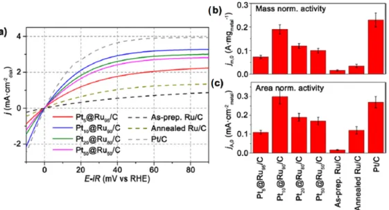
Figure 3.(a) Mass activity (MA) and (b) specific activity (SA) histograms for the Pt-based materials towards the oxygen reduction reaction (ORR). 0.5 M HClO4was used as electrolyte [54]. Reprinted with permission from [54]. Copyright American Chemical Society, 2004.
For Pt-Ni, the wide angle X-ray spectroscopy patterns, and the Debye function analysis showed that the as-prepared Pt-Ni electrocatalysts presented face-centered cubic structure and that the lattice parameter is reduced with the increase of Ni [55]. More important, both Pt-Cr and Pt-Ni alloys showed high tolerance to methanol than the Platinum electrocatalyst, Figure4.
Catalysts 2016, 6, 145 7 of 57
Figure 3. (a) Mass activity (MA) and (b) specific activity (SA) histograms for the Pt‐based materials towards the oxygen reduction reaction (ORR). 0.5 M HClO4 was used as electrolyte [54]. Reprinted with permission from [54]. Copyright American Chemical Society, 2004. For Pt‐Ni, the wide angle X‐ray spectroscopy patterns, and the Debye function analysis showed that the as‐prepared Pt‐Ni electrocatalysts presented face‐centered cubic structure and that the lattice parameter is reduced with the increase of Ni [55]. More important, both Pt‐Cr and Pt‐Ni alloys showed high tolerance to methanol than the Platinum electrocatalyst, Figure 4.
Figure 4. Methanol oxidation comparison for (a) Pt‐Cr (reprinted with permission from [54]. Copyright American Chemical Society, 2004 and (b) Pt‐Ni (reprinted with permission from [54]. Copyright Elsevier, 2005 in a 0.5 M HClO4 + 0.5 M CH3OH outgassed solution. The test conditions
were: Scan rate υ = 5 mV/s, and a rotating disk rate of 2000 rpm [54,60].
To explore the effect of the support material onto Pt NPs the synthesis of platinum supported on Vulcan‐carbon (Pt/C) and multi‐walled carbon nanotubes (Pt/MWCNTs), via the carbonyl chemical route, was done [61]. After 20 V cycles (CVs) from 0.05 to 1.2 V/RHE, an improved stability was obtained with Pt/MWCNT in comparison to Pt/C. This kinetics and stability improvement were attributed to a higher graphitization degree of MWCNT support, leading to an increased strength of the π‐sites with the MWCNTs acting as anchoring centers for Platinum nanoparticles [62]. Furthermore, this interaction also limited the agglomeration of Pt nanoparticles. Through a modification of the classic carbonyl chemical route, the synthesis of carbon supported Pt‐Ti nanoparticles was performed [63]. For the chemical composition, a post heat treatment process on the distribution of the particle size, and also on the electronic properties of Ti and Pt atoms on the performance on the oxygen reduction, and the methanol tolerance were done. The catalytic activity and selectivity towards methanol showed a remarkable enhancement for the nanoalloyed structure.
Figure 4.Methanol oxidation comparison for (a) Pt-Cr (reprinted with permission from [54]. Copyright American Chemical Society, 2004 and (b) Pt-Ni (reprinted with permission from [54]. Copyright Elsevier, 2005 in a 0.5 M HClO4+ 0.5 M CH3OH outgassed solution. The test conditions were: Scan rate υ = 5 mV/s, and a rotating disk rate of 2000 rpm [54,60].
Catalysts 2016, 6, 145 7 of 55
To explore the effect of the support material onto Pt NPs the synthesis of platinum supported on Vulcan-carbon (Pt/C) and multi-walled carbon nanotubes (Pt/MWCNTs), via the carbonyl chemical route, was done [61]. After 20 V cycles (CVs) from 0.05 to 1.2 V/RHE, an improved stability was obtained with Pt/MWCNT in comparison to Pt/C. This kinetics and stability improvement were attributed to a higher graphitization degree of MWCNT support, leading to an increased strength of the π-sites with the MWCNTs acting as anchoring centers for Platinum nanoparticles [62]. Furthermore, this interaction also limited the agglomeration of Pt nanoparticles.
Through a modification of the classic carbonyl chemical route, the synthesis of carbon supported Pt-Ti nanoparticles was performed [63]. For the chemical composition, a post heat treatment process on the distribution of the particle size, and also on the electronic properties of Ti and Pt atoms on the performance on the oxygen reduction, and the methanol tolerance were done. The catalytic activity and selectivity towards methanol showed a remarkable enhancement for the nanoalloyed structure. The improvement was caused by the annealing at 875◦C as a result of the alteration of the density of electrons present in the platinum d-orbitals modifying the strength of the oxygen adsorption. In consequence, the arrangement of a surface alloy with a high order degree is the responsible to mediate the methanol poisoning of platinum sites [63].
The carbonyl chemical route was further explored to synthesize, for the first time ever, carbon supported Pd NPs supported for the ORR [57]. Herein, K2PdCl6and sodium acetate were used as precursors reacting with CO. All of them were dissolved in CH3OH, a step which was the key in the modified process because this reaction has to be performed for 2 h in an ice-bath, in this way the reaction rate was decreased avoiding the agglomeration of particles during the complex formation. Thereafter, the process continued following the classical route. The synthesis process comparison for platinum- and palladium-based nanomaterials via carbonyl chemical route is contrasted in Figure5.
Catalysts 2016, 6, 145 8 of 57
The improvement was caused by the annealing at 875 °C as a result of the alteration of the density of electrons present in the platinum d‐orbitals modifying the strength of the oxygen adsorption. In consequence, the arrangement of a surface alloy with a high order degree is the responsible to mediate the methanol poisoning of platinum sites [63]. The carbonyl chemical route was further explored to synthesize, for the first time ever, carbon supported Pd NPs supported for the ORR [57]. Herein, K2PdCl6 and sodium acetate were used as precursors reacting with CO. All of them were dissolved in CH3OH, a step which was the key in the modified process because this reaction has to be performed for 2 h in an ice‐bath, in this way the reaction rate was decreased avoiding the agglomeration of particles during the complex formation. Thereafter, the process continued following the classical route. The synthesis process comparison for platinum‐ and palladium‐based nanomaterials via carbonyl chemical route is contrasted in Figure 5.
Figure 5. Process diagrams for the synthesis via the carbonyl route of platinum‐ and palladium‐based electrocatalysts [57]. Reprinted with permission from [57]. Copyright Elsevier, 2015. As a result of this process, Pd samples showed metal mass‐loading dependent morphologies. In 10 wt % Pd/C, Pd NPs were highly agglomerated on the carbon support. In Figure 6a, we can find many particles with an average diameter higher than 10 nm. For 20 wt % Pd/C, large amounts of Pd nanowires could be observed, see Figure 6b. In Figure 6c, it is possible to observe Pd nanorods which present an average diameter of 3 nm, these nanorods were well dispersed on the carbon support presenting a total composition of 30 wt % Pd/C. In Pd/C‐4, the nanoparticles were almost agglomerated, Figure 6d. In comparison with platinum‐based catalysts obtained by the carbonyl chemical route, the morphology of the palladium electrocatalysts changed depending on the metal mass loading [57].
Figure 5.Process diagrams for the synthesis via the carbonyl route of platinum- and palladium-based electrocatalysts [57]. Reprinted with permission from [57]. Copyright Elsevier, 2015.
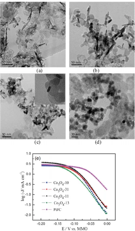
As a result of this process, Pd samples showed metal mass-loading dependent morphologies. In 10 wt % Pd/C, Pd NPs were highly agglomerated on the carbon support. In Figure6a, we can find many particles with an average diameter higher than 10 nm. For 20 wt % Pd/C, large amounts of Pd nanowires could be observed, see Figure6b. In Figure6c, it is possible to observe Pd nanorods which present an average diameter of 3 nm, these nanorods were well dispersed on the carbon support presenting a total composition of 30 wt % Pd/C. In Pd/C-4, the nanoparticles were almost agglomerated, Figure6d. In comparison with platinum-based catalysts obtained by the carbonyl
chemical route, the morphology of the palladium electrocatalysts changed depending on the metal mass loading [57].
The importance of this study lies in the description to control the morphology of palladium nanoparticles depending of the metal loading following the carbonyl route.Catalysts 2016, 6, 145 9 of 57
Figure 6. TEM images for (a) Pd/C 10%; (b) Pd/C 20%; (c) Pd/C 30% and (d) Pd/C 40% electrocatalysts.
The importance of this study lies in the description to control the morphology of palladium nanoparticles depending of the metal loading following the carbonyl route.
2.1.2. Transition Metal Chalcogenides
Transition metal chalcogenides are promising materials in the field of catalysis and photo‐ electrocatalysis, since they combine the properties of electrically conducting materials with the catalytic advantage of molecular metal‐clusters [64]. In the 70s, various research groups developed the so‐called Chevrel phases such as M6X8 (M = Mo; Re, X = S, Te and Se), having exceptional superconducting properties [65]. Perrin et al. [66] reported the synthesis and properties of MoxReySez
and MoxReyTez but also MoxRuySez, MoxRuyTez and MoxRhyTez [67]. The authors found that
molybdenum sulfide phases and those with mono or divalent elements, a rhombohedric structure with a triclinic deformation predominated. They assumed that Mo and Re d‐electron bands were responsible for the electrical superconductivity in these materials. All these samples were prepared by a direct synthesis from the elements in evacuated quartz ampoules, heated up to 1200 °C. The generated samples were ground and annealed at the same temperature for 24 h. To obtain the sulfide compounds, it was necessary to let the reaction take place near 1300 °C, and several subsequent heat treatments were necessary in order to get a pure sample. For selenide and the telluride clusters the synthesis was easier. In order to evaluate and manipulate the samples, the powders were converted into pellets and finally sintered [66,67]. The use of such transition metal chalcogenides (Mo4.2Ru1.8Se8) as electrocatalysts for the oxygen reduction in acid medium was reported in 1986 [68]. The authors reported the first test of such materials to perform the ORR with an appreciable cost advantage with respect to platinum [68]. It was further assessed that the Mo4.2Ru1.8Se8 cluster, in powder form fixed on supports with the help of of Nafion® ionomer thin film, onto glassy carbon, Figure 7a, and on p‐type gallium phosphide (p‐ GaP) semiconductor, Figure 7b, favored the ORR, and hydrogen evolution reaction (HER) under
Figure 6.TEM images for (a) Pd/C 10%; (b) Pd/C 20%; (c) Pd/C 30% and (d) Pd/C 40% electrocatalysts. 2.1.2. Transition Metal Chalcogenides
Transition metal chalcogenides are promising materials in the field of catalysis and photo-electrocatalysis, since they combine the properties of electrically conducting materials with the catalytic advantage of molecular metal-clusters [64]. In the 70s, various research groups developed the so-called Chevrel phases such as M6X8 (M = Mo; Re, X = S, Te and Se), having exceptional superconducting properties [65]. Perrin et al. [66] reported the synthesis and properties of MoxReySez and MoxReyTez but also MoxRuySez, MoxRuyTez and MoxRhyTez [67]. The authors found that molybdenum sulfide phases and those with mono or divalent elements, a rhombohedric structure with a triclinic deformation predominated. They assumed that Mo and Re d-electron bands were responsible for the electrical superconductivity in these materials. All these samples were prepared by a direct synthesis from the elements in evacuated quartz ampoules, heated up to 1200◦C. The generated samples were ground and annealed at the same temperature for 24 h. To obtain the sulfide compounds, it was necessary to let the reaction take place near 1300◦C, and several subsequent heat treatments were necessary in order to get a pure sample. For selenide and the telluride clusters the synthesis was easier. In order to evaluate and manipulate the samples, the powders were converted into pellets and finally sintered [66,67].
The use of such transition metal chalcogenides (Mo4.2Ru1.8Se8) as electrocatalysts for the oxygen reduction in acid medium was reported in 1986 [68]. The authors reported the first test of such materials to perform the ORR with an appreciable cost advantage with respect to platinum [68]. It was further assessed that the Mo4.2Ru1.8Se8cluster, in powder form fixed on supports with the help of of Nafion®ionomer thin film, onto glassy carbon, Figure7a, and on p-type gallium phosphide
Catalysts 2016, 6, 145 9 of 55
(p-GaP) semiconductor, Figure7b, favored the ORR, and hydrogen evolution reaction (HER) under Visible illumination [69]. Mo4.2Ru1.8Se8 clearly enhanced both processes. On p-GaP surface the photo- induced hydrogen evolution was maintained. The limiting currents were reduced by only 3% at
−
0.56 V (vs. SHE). This was quite remarkable and suggested (now a phenomenon well established) that hydrogen, besides protons, can penetrate the Nafion layer easily, curve 3, in Figure7b. The flat-band potential of the unmodified electrode was determined to be 0.94 V vs. SHE and was not shifted as a consequence of attachment of the Nafion film and the cluster particles.Catalysts 2016, 6, 145 10 of 57 Visible illumination [69]. Mo4.2Ru1.8Se8 clearly enhanced both processes. On p‐GaP surface the photo‐ induced hydrogen evolution was maintained. The limiting currents were reduced by only 3% at −0.56 V (vs. SHE). This was quite remarkable and suggested (now a phenomenon well established) that hydrogen, besides protons, can penetrate the Nafion layer easily, curve 3, in Figure 7b. The flat‐band potential of the unmodified electrode was determined to be 0.94 V vs. SHE and was not shifted as a consequence of attachment of the Nafion film and the cluster particles.
Figure 7. Linear scan voltammograms for the ORR (oxygen reduction reaction) and photo‐evolution of hydrogen of the Nafion‐attached cluster chalcogenides. (a) Glassy Carbon at 50 mV/s; and (b‐curve (3)) p‐GaP. Curve (B), in (a), is the unmodified GC surface. In (b), curves (1, 2) represent Nafion unmodified, and modified p‐GaP surfaces. Scan rate = 5 mV∙s−1. Adapted from [69].
Summing up, the Mo4.2Ru1.8S8 cluster employed as a model catalyst for multi‐electron reduction processes for the ORR, was not suitable for multi‐electron oxidation processes—the oxygen evolution reaction (OER), due to insufficient kinetic stabilization [69]. Based on previous works [70,71], a certain degree of kinetic stabilization can be accomplished with chalcogenides, which can permit a photoreaction of holes via transition‐metal d‐states which are not significantly mixed with chalcogen states. Regarding the electrochemical activity towards the ORR, Mo4.2Ru1.8S8, Figure 8, a pseudo ternary cluster, outperformed the ternary clusters, e.g., Ni0.85Mo6Te8, where Ni atoms occupies the free sites in the channels between the Mo‐clusters. Two main positive effects on the pseudo ternary compound were claimed, namely, the increase of metal‐metal distance in the cluster, thus possibly facilitating the breaking of the –oxygen–oxygen– bond liberating OH− ions. The expected shift of the electronic levels upwards was caused by the increase of the charge in the cluster.
Figure 8. Structure of a pseudo ternary cluster (Mo4Ru2)Se8.
Figure 7.Linear scan voltammograms for the ORR (oxygen reduction reaction) and photo-evolution of hydrogen of the Nafion-attached cluster chalcogenides. (a) Glassy Carbon at 50 mV/s; and (b-curve (3)) p-GaP. Curve (B), in (a), is the unmodified GC surface. In (b), curves (1, 2) represent Nafion unmodified, and modified p-GaP surfaces. Scan rate = 5 mV·s−1. Adapted from [69].
Summing up, the Mo4.2Ru1.8S8cluster employed as a model catalyst for multi-electron reduction processes for the ORR, was not suitable for multi-electron oxidation processes—the oxygen evolution reaction (OER), due to insufficient kinetic stabilization [69]. Based on previous works [70,71], a certain degree of kinetic stabilization can be accomplished with chalcogenides, which can permit a photoreaction of holes via transition-metal d-states which are not significantly mixed with chalcogen states. Regarding the electrochemical activity towards the ORR, Mo4.2Ru1.8S8, Figure 8, a pseudo ternary cluster, outperformed the ternary clusters, e.g., Ni0.85Mo6Te8, where Ni atoms occupies the free sites in the channels between the Mo-clusters. Two main positive effects on the pseudo ternary compound were claimed, namely, the increase of metal-metal distance in the cluster, thus possibly facilitating the breaking of the –oxygen–oxygen– bond liberating OH−ions. The expected shift of the electronic levels upwards was caused by the increase of the charge in the cluster.
Catalysts 2016, 6, 145 10 of 57 Visible illumination [69]. Mo4.2Ru1.8Se8 clearly enhanced both processes. On p‐GaP surface the photo‐ induced hydrogen evolution was maintained. The limiting currents were reduced by only 3% at −0.56 V (vs. SHE). This was quite remarkable and suggested (now a phenomenon well established) that hydrogen, besides protons, can penetrate the Nafion layer easily, curve 3, in Figure 7b. The flat‐band potential of the unmodified electrode was determined to be 0.94 V vs. SHE and was not shifted as a consequence of attachment of the Nafion film and the cluster particles.
Figure 7. Linear scan voltammograms for the ORR (oxygen reduction reaction) and photo‐evolution of hydrogen of the Nafion‐attached cluster chalcogenides. (a) Glassy Carbon at 50 mV/s; and (b‐curve (3)) p‐GaP. Curve (B), in (a), is the unmodified GC surface. In (b), curves (1, 2) represent Nafion unmodified, and modified p‐GaP surfaces. Scan rate = 5 mV∙s−1. Adapted from [69].
Summing up, the Mo4.2Ru1.8S8 cluster employed as a model catalyst for multi‐electron reduction processes for the ORR, was not suitable for multi‐electron oxidation processes—the oxygen evolution reaction (OER), due to insufficient kinetic stabilization [69]. Based on previous works [70,71], a certain degree of kinetic stabilization can be accomplished with chalcogenides, which can permit a photoreaction of holes via transition‐metal d‐states which are not significantly mixed with chalcogen states. Regarding the electrochemical activity towards the ORR, Mo4.2Ru1.8S8, Figure 8, a pseudo ternary cluster, outperformed the ternary clusters, e.g., Ni0.85Mo6Te8, where Ni atoms occupies the free sites in the channels between the Mo‐clusters. Two main positive effects on the pseudo ternary compound were claimed, namely, the increase of metal‐metal distance in the cluster, thus possibly facilitating the breaking of the –oxygen–oxygen– bond liberating OH− ions. The expected shift of the electronic levels upwards was caused by the increase of the charge in the cluster.
Figure 8. Structure of a pseudo ternary cluster (Mo4Ru2)Se8.
Because the catalytic properties and the high density of d states at the Fermi level can be related, this relation on Mo4Ru2Se8, Mo2Re4Se8, Mo6Se8, and the Mo metal was undertaken [72]. Indeed, Mo6Se8showed metallic properties, whereas Mo4Ru2Se8and Mo2Re4Se8showed semiconducting properties. The explanation lies on the fact that the substitution of Mo by Re and/or Ru atoms, that contain a high valence electron number, causes an increment of the electrons from 20 to 24 in the cluster M6X8, resulting in a filling of the eg band. This effect shifts upwards the Fermi level, as schematized in Figure9.
Catalysts 2016, 6, 145 11 of 57
Because the catalytic properties and the high density of d states at the Fermi level can be related, this relation on Mo4Ru2Se8, Mo2Re4se8, Mo6Se8, and the Mo metal was undertaken [72]. Indeed, Mo6Se8 showed metallic properties, whereas Mo4Ru2Se8 and Mo2Re4Se8 showed semiconducting properties. The explanation lies on the fact that the substitution of Mo by Re and/or Ru atoms, that contain a high valence electron number, causes an increment of the electrons from 20 to 24 in the cluster M6X8, resulting in a filling of the eg band. This effect shifts upwards the Fermi level, as schematized in Figure 9.
Figure 9. Band structure scheme of chalcogenide clusters. Adapted from [72,73]. Reprinted with permission from [72]. Copyright Elsevier, 1988.
These compounds were evaluated towards HER and ORR. As a result of the narrow energy band caused by the d‐state density, some improvement was observed on the HER, with a significant influence on ORR. This study revealed that hydrogen species solely interact with individual metal atoms, the molecular oxygen interacts with the atoms M, and M’ in the (MM’)6X8 cluster [74], as shown in Figure 10, thus forming a surface transition metal complex. Based on the statistics of the calculated possible combinations and taking again into account the density of d states, the complex IV must play a major role in the ORR electrocatalytic materials activity.
Figure 10. Surface transition metal complexes and their bridge‐type, interaction with the chemisorbed oxygen, modified from [72]. Reprinted with permission from [72]. Copyright Elsevier, 1998.
Based on these Chevrel phase model compounds, prepared in quartz ampoule at high temperature [67], Mo‐Ru‐Se, in powder and/or in thin layer form, was synthesized via a soft chemical method; the carbonyl chemical route by reacting molybdenum hexacarbonyl, tris‐ruthenium dodecacarbonyl and selenium powder in xylene [75]. The XPS (X‐ray photoelectron spectroscopy) characterization revealed the presence of SeO2 and MoO3, Figure 11. After cathodic electrochemical treatment, in presence or absence of oxygen at 0.35 V during 5 min in 0.5 M H2SO4, the emission line for SeO2, disappears and the MoO3, emission line is strongly reduced, see curves (2) in Figure 11, indicating that the catalysts still contain a small amount of Mo. Exposed to air for more than 100 days, curves (3), the MoO3 species is further reduced to a minimum in comparison to the shortly treated electrode, curves (2). The absence of SeO2, species demonstrates a higher stability than Chevrel phase compounds against oxidation under oxygen atmosphere [13].
Figure 9. Band structure scheme of chalcogenide clusters. Adapted from [72,73]. Reprinted with permission from [72]. Copyright Elsevier, 1988.
These compounds were evaluated towards HER and ORR. As a result of the narrow energy band caused by the d-state density, some improvement was observed on the HER, with a significant influence on ORR. This study revealed that hydrogen species solely interact with individual metal atoms, the molecular oxygen interacts with the atoms M, and M’ in the (MM’)6X8cluster [74], as shown in Figure10, thus forming a surface transition metal complex. Based on the statistics of the calculated possible combinations and taking again into account the density of d states, the complex IV must play a major role in the ORR electrocatalytic materials activity.
Catalysts 2016, 6, 145 11 of 57
Because the catalytic properties and the high density of d states at the Fermi level can be related, this relation on Mo4Ru2Se8, Mo2Re4se8, Mo6Se8, and the Mo metal was undertaken [72]. Indeed, Mo6Se8 showed metallic properties, whereas Mo4Ru2Se8 and Mo2Re4Se8 showed semiconducting properties. The explanation lies on the fact that the substitution of Mo by Re and/or Ru atoms, that contain a high valence electron number, causes an increment of the electrons from 20 to 24 in the cluster M6X8, resulting in a filling of the eg band. This effect shifts upwards the Fermi level, as schematized in Figure 9.
Figure 9. Band structure scheme of chalcogenide clusters. Adapted from [72,73]. Reprinted with permission from [72]. Copyright Elsevier, 1988.
These compounds were evaluated towards HER and ORR. As a result of the narrow energy band caused by the d‐state density, some improvement was observed on the HER, with a significant influence on ORR. This study revealed that hydrogen species solely interact with individual metal atoms, the molecular oxygen interacts with the atoms M, and M’ in the (MM’)6X8 cluster [74], as shown in Figure 10, thus forming a surface transition metal complex. Based on the statistics of the calculated possible combinations and taking again into account the density of d states, the complex IV must play a major role in the ORR electrocatalytic materials activity.
Figure 10. Surface transition metal complexes and their bridge‐type, interaction with the chemisorbed oxygen, modified from [72]. Reprinted with permission from [72]. Copyright Elsevier, 1998.
Based on these Chevrel phase model compounds, prepared in quartz ampoule at high temperature [67], Mo‐Ru‐Se, in powder and/or in thin layer form, was synthesized via a soft chemical method; the carbonyl chemical route by reacting molybdenum hexacarbonyl, tris‐ruthenium dodecacarbonyl and selenium powder in xylene [75]. The XPS (X‐ray photoelectron spectroscopy) characterization revealed the presence of SeO2 and MoO3, Figure 11. After cathodic electrochemical treatment, in presence or absence of oxygen at 0.35 V during 5 min in 0.5 M H2SO4, the emission line for SeO2, disappears and the MoO3, emission line is strongly reduced, see curves (2) in Figure 11, indicating that the catalysts still contain a small amount of Mo. Exposed to air for more than 100 days, curves (3), the MoO3 species is further reduced to a minimum in comparison to the shortly treated electrode, curves (2). The absence of SeO2, species demonstrates a higher stability than Chevrel phase compounds against oxidation under oxygen atmosphere [13].
Figure 10.Surface transition metal complexes and their bridge-type, interaction with the chemisorbed oxygen, modified from [72]. Reprinted with permission from [72]. Copyright Elsevier, 1998.
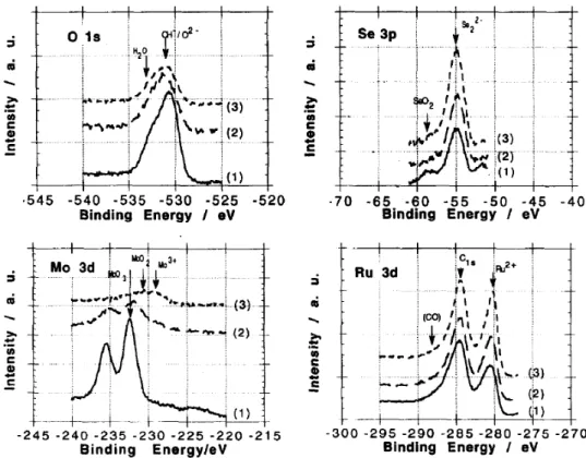
Based on these Chevrel phase model compounds, prepared in quartz ampoule at high temperature [67], Mo-Ru-Se, in powder and/or in thin layer form, was synthesized via a soft chemical method; the carbonyl chemical route by reacting molybdenum hexacarbonyl, tris-ruthenium dodecacarbonyl and selenium powder in xylene [75]. The XPS (X-ray photoelectron spectroscopy) characterization revealed the presence of SeO2and MoO3, Figure11. After cathodic electrochemical treatment, in presence or absence of oxygen at 0.35 V during 5 min in 0.5 M H2SO4, the emission line for SeO2, disappears and the MoO3, emission line is strongly reduced, see curves (2) in Figure11, indicating that the catalysts still contain a small amount of Mo. Exposed to air for more than 100 days, curves (3), the MoO3species is further reduced to a minimum in comparison to the shortly treated electrode, curves (2). The absence of SeO2, species demonstrates a higher stability than Chevrel phase compounds against oxidation under oxygen atmosphere [13].
Catalysts 2016, 6, 145 11 of 55
Catalysts 2016, 6, 145 12 of 57
Figure 11. XPS (X‐ray photoelectron spectroscopy) spectra of (Ru1−xMox)ySeOz at different conditions;
(1) as prepared sample in xylene solution; (2) polarized sample at +0.35 V/NHE (5 min) in 0.5 M H2SO4; and (3) after ORR and kept in air approximately 100 days. Reprinted with permission from [75]. Copyright Elsevier, 1994.
The Extended X‐ray absorption fine structure spectroscopy (EXAFS) disclosed that chemically
generated Mo‐Ru‐Se electrocatalysts were, structurally speaking, different to that of the Chevrel
phase compound [64]. It was concluded that the Mo and Ru atoms, in Mo‐Ru‐Se, were located as
independent phases: MoSe
x, MoO
xand RuSe
x[76]. They, however, showed high selectivity to perform
the ORR, in a solution containing methanol, with a four‐electron reaction pathway, with an activity
nevertheless, lower than that of the standard Pt catalysts in methanol‐free electrolyte [77].
A further characterization by X‐ray diffraction at wide angles (WAXS) of Ru
xand Ru
xSe
ywas
carried out [78]. Indeed, chalcogenide particles produced from the reaction between Ru
3(CO)
12and
Se were more resistant to oxidation than monometallic Ru
xnanoparticles with similar size. This
phenomenon was associated to the coordination of Selenium atoms over the ruthenium atoms surface.
As revealed by EXAFS analysis [79,80] the closest Ru‐Ru averaged distance was 2.64 Å
(corresponding to the hcp phase of metallic ruthenium) and that of the metal chalcogenide Ru‐Se was
2.43 Å. It is worth noting that the calculated Debye‐Waller parameters were a factor of 2 higher for
the Ru‐Se coordination distance than for Ru‐Ru. Considering a particle diameter of 17 Å a pure
ruthenium cluster‐like model particle was developed containing 153 atoms (Ru
153). This is the third
species in a series of hcp closed shell clusters with “magic” numbers 13, 57, 153, 323, etc. Therefore,
within the hcp cluster model (17 Å particle size, 153 atoms), the number of ruthenium atoms available
for electrocatalytic purposes at the surface of such cluster can be 153 − 57 = 96. Because x = 2 and y =
1 in the chalcogenide material, Ru
xSe
y, the cluster model contains 99 Ru atoms and 54 Se atoms, with
an increased disorder of selenium atoms, deduced from EXAFS calculations [79], almost all selenium
atoms are coordinated to ruthenium atoms on the cluster in a statistical way, as shown in Figure 12.
In this way, the Ru‐clusters surface coverage by Se atoms induces the necessary free active sites
(Ruthenium sites) to perform an efficient coordination with oxygen/water [78].
Figure 11.XPS (X-ray photoelectron spectroscopy) spectra of (Ru1−xMox)ySeOzat different conditions; (1) as prepared sample in xylene solution; (2) polarized sample at +0.35 V/NHE (5 min) in 0.5 M H2SO4; and (3) after ORR and kept in air approximately 100 days. Reprinted with permission from [75]. Copyright Elsevier, 1994.
The Extended X-ray absorption fine structure spectroscopy (EXAFS) disclosed that chemically generated Mo-Ru-Se electrocatalysts were, structurally speaking, different to that of the Chevrel phase compound [64]. It was concluded that the Mo and Ru atoms, in Mo-Ru-Se, were located as independent phases: MoSex, MoOxand RuSex[76]. They, however, showed high selectivity to perform the ORR, in a solution containing methanol, with a four-electron reaction pathway, with an activity nevertheless, lower than that of the standard Pt catalysts in methanol-free electrolyte [77].
A further characterization by X-ray diffraction at wide angles (WAXS) of Ruxand RuxSeywas carried out [78]. Indeed, chalcogenide particles produced from the reaction between Ru3(CO)12 and Se were more resistant to oxidation than monometallic Rux nanoparticles with similar size. This phenomenon was associated to the coordination of Selenium atoms over the ruthenium atoms surface. As revealed by EXAFS analysis [79,80] the closest Ru-Ru averaged distance was 2.64 Å (corresponding to the hcp phase of metallic ruthenium) and that of the metal chalcogenide Ru-Se was 2.43 Å. It is worth noting that the calculated Debye-Waller parameters were a factor of 2 higher for the Ru-Se coordination distance than for Ru-Ru. Considering a particle diameter of 17 Å a pure ruthenium cluster-like model particle was developed containing 153 atoms (Ru153). This is the third species in a series of hcp closed shell clusters with “magic” numbers 13, 57, 153, 323, etc. Therefore, within the hcp cluster model (17 Å particle size, 153 atoms), the number of ruthenium atoms available for electrocatalytic purposes at the surface of such cluster can be 153
−
57 = 96. Because x = 2 and y = 1 in the chalcogenide material, RuxSey, the cluster model contains 99 Ru atoms and 54 Se atoms, with an increased disorder of selenium atoms, deduced from EXAFS calculations [79], almost all selenium atoms are coordinated to ruthenium atoms on the cluster in a statistical way, as shown in Figure12. In this way, the Ru-clusters surface coverage by Se atoms induces the necessary free active sites (Ruthenium sites) to perform an efficient coordination with oxygen/water [78].Catalysts 2016, 6, 145 13 of 57
Figure 12. hcp‐Cluster Model structures for Ru99Se54; (a) Se statistically bonded onto the Ru clusters; (b) Se replacing Ru surface atoms in an ordered positioning with 5‐, 6‐, and 7‐ fold coordinated. The use of selenium atoms to coordinate catalytic center surface atoms, as well as impinging on it electronic modification was demonstrated for ruthenium in RuxSey [81]. This concept was further applied onto platinum, generated via the carbonyl chemical route [82]. The surface Pt NPs in Pt/C was modified with Se (selenization process). Platinum supported on carbon and SeO2 were mixed in isopropanol solution with specific quantities and stirred for 12 h at room temperature. This mixture (20 wt % PtxSey/C) was heat‐treated (200 °C) for 1 h under a nitrogen atmosphere. In order to account the optimal amount of Se atoms, to allow the adsorption and subsequent reduction of O2 molecules, Se was concomitantly stripped from the Pt surface using Chronoamperometry at different stripping times, at an established anodic potential. Employing a stripping time of 20 min at 1.1 V/RHE, the ORR half‐wave potential (E1/2) shifted to positive values, whereas the OCP (open circuit potential) remained constant. The optimal Se coverage (see arrow in Figure 13a) kept to a maximum the ORR in the presence of methanol [83]. The partial leaching of Se atoms from the Pt surface improved the activity of PtxSey/C towards the oxygen reduction, with a high tolerance as compared to Pt/C, Figure 13.
Figure 13. (a) PtxSey/C (20 mg of 20 wt %) ORR half‐wave potentials compared to Pt/C (dotted lines). Both electrocatalysts were evaluated at 900 rpm in oxygen‐saturated 0.5 M H2SO4 + 0.5 M CH3OH (filled circles, left axes) and 0.5 M H2SO4 (empty symbols, right axes). (b) Linear scan voltammetries for the same test [83]. Reprinted with permission from [83]. Copyright John Wiley and Sons, 2013. 2.2. Non‐Precious Catalysts Despite the efforts carried out in the production of novel and efficient electrocatalyst, platinum‐ based materials are still one of the most efficient oxygen reduction catalysts employed in PEMFCs [84]; however, their high cost, low abundance and poor durability are a main obstacle in the development of PEMFCs [85]. To overcome these issues, the search of non‐precious metal ORR catalysts has been extensively conducted in recent years [86]. Pt‐free catalysts such as transition‐metal chalcogenides have shown promising activities towards fuel cell reactions [51]. Co and Fe are also promising cathodic catalyst centers [87]. In recent studies, researchers have focused their efforts on two kinds of non‐precious metals as catalytic centers: Co and Fe, and transition‐metal chalcogenides with application in the ORR [88]. The development of new non‐precious electrocatalyst dates back to the seventies with Co3S4 and Me(a)Me2(b)X4 (Me(a) = Mn, Fe, Co, Ni, Cu or Zn, Me(b) = Ti, V, Cr, Fe, Co or Ni, X = O, S, Se or Te). This
Figure 12. hcp-Cluster Model structures for Ru99Se54; (a) Se statistically bonded onto the Ru clusters; (b) Se replacing Ru surface atoms in an ordered positioning with 5-, 6-, and 7- fold coordinated.
The use of selenium atoms to coordinate catalytic center surface atoms, as well as impinging on it electronic modification was demonstrated for ruthenium in RuxSey[81]. This concept was further applied onto platinum, generated via the carbonyl chemical route [82]. The surface Pt NPs in Pt/C was modified with Se (selenization process). Platinum supported on carbon and SeO2were mixed in isopropanol solution with specific quantities and stirred for 12 h at room temperature. This mixture (20 wt % PtxSey/C) was heat-treated (200◦C) for 1 h under a nitrogen atmosphere. In order to account the optimal amount of Se atoms, to allow the adsorption and subsequent reduction of O2 molecules, Se was concomitantly stripped from the Pt surface using Chronoamperometry at different stripping times, at an established anodic potential. Employing a stripping time of 20 min at 1.1 V/RHE, the ORR half-wave potential (E1/2) shifted to positive values, whereas the OCP (open circuit potential) remained constant. The optimal Se coverage (see arrow in Figure13a) kept to a maximum the ORR in the presence of methanol [83]. The partial leaching of Se atoms from the Pt surface improved the activity of PtxSey/C towards the oxygen reduction, with a high tolerance as compared to Pt/C, Figure13. Catalysts 2016, 6, 145 13 of 57
Figure 12. hcp‐Cluster Model structures for Ru99Se54; (a) Se statistically bonded onto the Ru clusters; (b) Se replacing Ru surface atoms in an ordered positioning with 5‐, 6‐, and 7‐ fold coordinated. The use of selenium atoms to coordinate catalytic center surface atoms, as well as impinging on it electronic modification was demonstrated for ruthenium in RuxSey [81]. This concept was further applied onto platinum, generated via the carbonyl chemical route [82]. The surface Pt NPs in Pt/C was modified with Se (selenization process). Platinum supported on carbon and SeO2 were mixed in isopropanol solution with specific quantities and stirred for 12 h at room temperature. This mixture (20 wt % PtxSey/C) was heat‐treated (200 °C) for 1 h under a nitrogen atmosphere. In order to account the optimal amount of Se atoms, to allow the adsorption and subsequent reduction of O2 molecules, Se was concomitantly stripped from the Pt surface using Chronoamperometry at different stripping times, at an established anodic potential. Employing a stripping time of 20 min at 1.1 V/RHE, the ORR
half‐wave potential (E1/2) shifted to positive values, whereas the OCP (open circuit potential) remained constant. The optimal Se coverage (see arrow in Figure 13a) kept to a maximum the ORR in the presence of methanol [83]. The partial leaching of Se atoms from the Pt surface improved the activity of PtxSey/C towards the oxygen reduction, with a high tolerance as compared to Pt/C, Figure 13.
Figure 13. (a) PtxSey/C (20 mg of 20 wt %) ORR half‐wave potentials compared to Pt/C (dotted lines). Both electrocatalysts were evaluated at 900 rpm in oxygen‐saturated 0.5 M H2SO4 + 0.5 M CH3OH (filled circles, left axes) and 0.5 M H2SO4 (empty symbols, right axes). (b) Linear scan voltammetries for the same test [83]. Reprinted with permission from [83]. Copyright John Wiley and Sons, 2013. 2.2. Non‐Precious Catalysts Despite the efforts carried out in the production of novel and efficient electrocatalyst, platinum‐ based materials are still one of the most efficient oxygen reduction catalysts employed in PEMFCs [84]; however, their high cost, low abundance and poor durability are a main obstacle in the development of PEMFCs [85]. To overcome these issues, the search of non‐precious metal ORR catalysts has been extensively conducted in recent years [86]. Pt‐free catalysts such as transition‐metal chalcogenides have shown promising activities towards fuel cell reactions [51]. Co and Fe are also promising cathodic catalyst centers [87]. In recent studies, researchers have focused their efforts on two kinds of non‐precious metals as catalytic centers: Co and Fe, and transition‐metal chalcogenides with application in the ORR [88]. The development of new non‐precious electrocatalyst dates back to the seventies with Co3S4 and Me(a)Me2(b)X4 (Me(a) = Mn, Fe, Co, Ni, Cu or Zn, Me(b) = Ti, V, Cr, Fe, Co or Ni, X = O, S, Se or Te). This
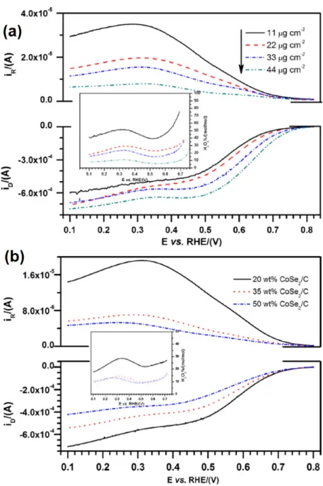
Figure 13.(a) PtxSey/C (20 mg of 20 wt %) ORR half-wave potentials compared to Pt/C (dotted lines). Both electrocatalysts were evaluated at 900 rpm in oxygen-saturated 0.5 M H2SO4+ 0.5 M CH3OH (filled circles, left axes) and 0.5 M H2SO4(empty symbols, right axes). (b) Linear scan voltammetries for the same test [83]. Reprinted with permission from [83]. Copyright John Wiley and Sons, 2013.
2.2. Non-Precious Catalysts
Despite the efforts carried out in the production of novel and efficient electrocatalyst, platinum-based materials are still one of the most efficient oxygen reduction catalysts employed in PEMFCs [84]; however, their high cost, low abundance and poor durability are a main obstacle in the development of PEMFCs [85]. To overcome these issues, the search of non-precious metal ORR catalysts has been extensively conducted in recent years [86]. Pt-free catalysts such as transition-metal chalcogenides have shown promising activities towards fuel cell reactions [51]. Co and Fe are also promising cathodic catalyst centers [87]. In recent studies, researchers have focused their efforts on two kinds of non-precious metals as catalytic centers: Co and Fe, and transition-metal chalcogenides with application in the ORR [88].
![Figure 2. Particle size of the electrocatalysts (a) Pt‐Sn/C (carbonyl route); (b) Pt‐Sn/C Etek, and (c) Pt/C Etek [59] obtained by TEM (transmission electron microscopy). The <d> parameter was determined by a Gaussian distribution. Reprinted with](https://thumb-eu.123doks.com/thumbv2/123doknet/14799754.605614/6.892.203.688.657.1017/particle-electrocatalysts-transmission-microscopy-parameter-determined-distribution-reprinted.webp)

![Figure 9. Band structure scheme of chalcogenide clusters. Adapted from [72,73]. Reprinted with permission from [72] . Copyright Elsevier, 1988.](https://thumb-eu.123doks.com/thumbv2/123doknet/14799754.605614/11.892.307.587.292.517/structure-chalcogenide-clusters-adapted-reprinted-permission-copyright-elsevier.webp)
![Figure 19. HOR on Pd/C, Pd 5 P 2 /C and PdP 2 /C electrocatalysts in 0.1 M HClO 4 at 298 K [125].](https://thumb-eu.123doks.com/thumbv2/123doknet/14799754.605614/19.892.264.627.472.753/figure-hor-pd-c-pd-pdp-electrocatalysts-hclo.webp)
![Figure 26. (a) TEM image for CoSe 2 /NCNH sample. (b) Tafel plot for ORR on CoSe 2 /NCNH, CoSe 2 /CNH, CoSe 2 /C and NCNH. Reprinted with permission from [229]. Copyright John Wiley &](https://thumb-eu.123doks.com/thumbv2/123doknet/14799754.605614/26.892.173.707.578.812/figure-image-sample-tafel-reprinted-permission-copyright-wiley.webp)
