HAL Id: cea-02489500
https://hal-cea.archives-ouvertes.fr/cea-02489500
Submitted on 24 Feb 2020HAL is a multi-disciplinary open access
archive for the deposit and dissemination of sci-entific research documents, whether they are pub-lished or not. The documents may come from teaching and research institutions in France or abroad, or from public or private research centers.
L’archive ouverte pluridisciplinaire HAL, est destinée au dépôt et à la diffusion de documents scientifiques de niveau recherche, publiés ou non, émanant des établissements d’enseignement et de recherche français ou étrangers, des laboratoires publics ou privés.
Numerical analysis of core thermal-hydraulic for
sodium-cooled fast reactors
A. Conti, A. Gerschenfeld, Y. Gorsse, T. Cadiou, R. Lavastre
To cite this version:
A. Conti, A. Gerschenfeld, Y. Gorsse, T. Cadiou, R. Lavastre. Numerical analysis of core thermal-hydraulic for sodium-cooled fast reactors. NURETH 2015 - 16th International Topical Meeting on Nuclear Reactor Thermal Hydraulics, Aug 2015, Chicago, United States. �cea-02489500�
NUMERICAL ANALYSIS OF CORE THERMAL-HYDRAULIC FOR
SODIUM-COOLED FAST REACTORS
Alain CONTI1, Antoine GERSCHENFELD2, Yannick GORSSE2,
1
: Reactor Studies Department, Nuclear Energy Division, CEA Cadarache, 13115 St Paul Lez Durance, France
2
:System&Structure Modelling Department, Nuclear Energy Division, CEA Saclay, 91191 Gif-sur-Yvette France
[email protected]; [email protected] ; [email protected] Thierry CADIOU1, Romain LAVASTRE1
[email protected]
; [email protected]ABSTRACT
The paper presents the numerical analysis of core thermal-hydraulic performed by CEA for Sodium-cooled Fast Reactors (SFR). The core thermal-hydraulic analyses are performed at three scales:
The individual sub-assembly, characterized by pin bundle with helical space wire.
In the 1980s, a specific sub-channel scale model for SFR-type subassemblies was developed at CEA. In 2008, this model was re-implemented in the Trio_U CFD code, under the name Trio_U MC (Core Model), for use in design phase. Besides this channel model, refined CFD models of the sub-assembly were also developed. Some examples (sodium or clad temperature inside the bundle) are presented.
The whole sub-assemblies.
The main objective is to determine the core steady-state hydraulic conditions, for specific objectives, such as obtaining a required mean outlet core temperature while keeping the maximum cladding temperature within a given limit: in practice, this is achieved by allocating the fuel sub-assemblies among a number of flow-rate zones. The paper describes the methodology to determine the number and flow zones allocation and the corresponding mass flow rates with Trio_U MC, as well as the associated optimization process.
The whole core, with sub-assemblies, inter-wrapper gaps and the hot pool plenum.
A model for the interaction of the core sub-assemblies with the adjoining inter-wrapper gaps and with the hot pool plenum has been developed at CEA. Known as Trio_U MC2, it consists in a code coupling of Trio_U MC with a Trio_U CFD domain representing the inter-wrapper gaps and hot pool plenum. This model leads to tube temperatures in the reactor nominal state.
KEYWORDS
1. INTRODUCTION
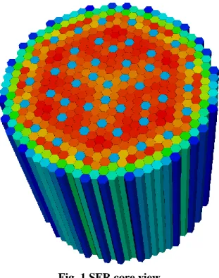
Thermal-hydraulic is recognized as a key scientific subject in the development of SFR. A SFR core is composed of hexagonal sub-assemblies (Fig. 1), and thorough understanding of its thermal-hydraulic behavior is essential [1].
Fig. 1 SFR core view
Numerical analysis of core thermal-hydraulic is required for design and safety purposes. Permanent calculations for the nominal and partial operating conditions and unsteady calculations for the transient conditions must be considered.
Numerical analyses are performed at three scales:
The individual fuel sub-assembly (S/As), characterized by pin bundle with helical space wire.
The whole S/As.
The whole core, with S/As and inter-wrappers gaps, as well as the hot pool plenum.
The main parameters to be evaluated in the thermal-hydraulic studies are the pressure, temperature and velocity distributions in the sub-assembly that helps to determine the following quantities:
The clad temperature and especially the clad maximum temperature.
The temperature gradients and the maximum temperature of the coolant liquid sodium.
The hexagonal can temperatures for thermo-mechanical analysis.
The mass flow rate for each fuel S/As.
2. INDIVIDUAL FUEL SUB-ASSEMBLY THERMAL-HYDRAULIC 2.1 Numerical Analysis Needs
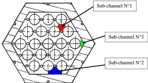
The fuel sub-assembly consists of a hexagonal duct wall with fuel pins tube (Fig. 2). The cylindrical fuel pins are arranged in a triangular lattice. The fuel pins are separated from each other by a helical wire wrap called spacer wire.
The sodium and pin clad temperature calculations require an accurate knowledge of the global and local thermal-hydraulic field in the pin bundle. One important feature is the transversal flow and the mixing induced by the space wire-wrapped which imposes local thermal-hydraulic coupling between sub-channels.
There are three kinds of sub-channels (Fig. 2), with different section areas: triangular (N° 1) in most of the bundle, rectangular along the hexagonal can (N°2) and corner ones (N°3). Due to different shape of the sub-channels, the thermal-hydraulic characteristics of the sodium flowing through the sub-assembly are also different which needs a thorough and deep understanding.
Fig. 2 SFR S/As schematic view with its different sub-channels
2.2 Trio_U MC Application in Trio_U Code 2.2.1 Presentation
In the 1980s, a specific model was developed at CEA based on sub-channel averaging for pressure, velocity and temperature (in the framework of design SFR studies for Phenix and Superphenix [2]). Transport of averaged quantities of mass, momentum and energy between two adjacent sub-channels is based on analytical and experimental data. The deviated flow rate induced by the wire is modelled with some assumptions. For pressure drop evaluation, reference friction factor models are used.
Hence, the modelling scale used is intermediate between a “refined CFD” scale (where one would represent detailed local geometric shapes) and the "system" scale (where one would simulate the S/As as
Sub-channel N°1
Sub-channel N°3
a 1D section). In 2008, this model was implemented in the Trio_U code (a Computational Fluid Dynamic (CFD) code developed at CEA for 3D thermal-hydraulic studies [2]) under the name Trio_U MC.
Trio_U MC allows taking into account inhomogeneous radial and axial thermal-hydraulic fields within each sub-assembly, while having a short calculation time (few minutes for a steady-state calculation of all sub-assemblies).
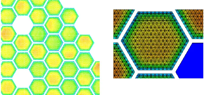
The Fig. 3 shows on left a partial view of an SFR core (in blue and green, free-fuel S/As); the right part presents the corresponding sub-channel modelling.
Fig. 3 Trio_U MC application – Modelling type
2.2.2 Some results
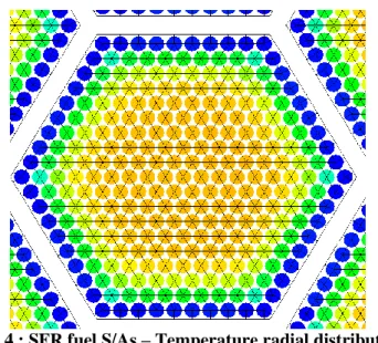
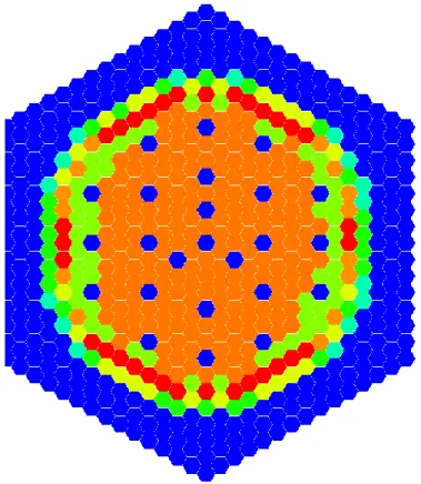
An example of a Trio_U MC computation for an SFR fuel S/As (in nominal working operation) is shown in Fig. 4:
The higher flow sections on the edge on the bundle result in a higher cooling of the first peripheral pin row (blue color): this effect is spread by space wire mixing to the second and third rows (green colors). Hence, they exhibit lower outer temperatures than the mean S/As one.
Other rows (yellow and orange) exit equal or higher than the mean S/As temperature; the hottest sub-channels correspond to fuel S/As thermal-hydraulic “hot spots”.
In this case, the radial temperature distribution (sodium and pin clad) has the same 1/12 symmetry as the S/As geometry.
Fig. 4 : SFR fuel S/As – Temperature radial distribution
In operating conditions, temperature heterogeneities calculated by the code in a S/As at bundle outlet are the following:
About 30 °C between the hot sub-channels and the mean temperature.
About 80 °C for the radial gradient temperature.
2.3 Transient Studies
The knowledge of thermal-hydraulic fields within each sub-assembly is also necessary in incident and accident transient scenarios (a specific paper details corresponding computational thermal-hydraulics schemes [3]). Especially in Loss of Flow (LOF) cases, they lead to sodium and clad pin temperature elevations; it is essential to calculate corresponding distributions within fuel S/As.
To perform numerical analyses, Trio_U MC application is used in combination with a system code, such CATHARE [4]:
First, a CATHARE calculation takes place in order to obtain core power and core flow rate evolutions during the LOF [5]; these results are used as boundary conditions for Trio_U MC calculations.
Then, Trio_U MC is used with the previous boundary conditions to compute the local behavior of the core during the transient (including reverse flow and natural convection), in order to determine the fuel S/As temperature evolution s over the transient.
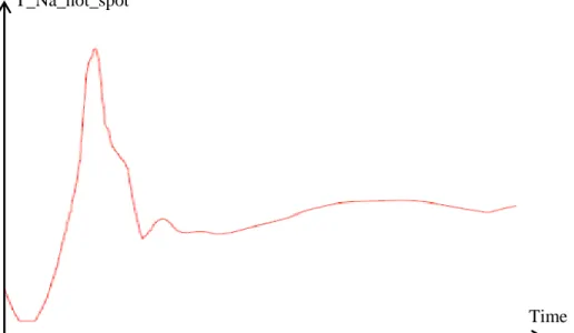
The calculations enable to access to sodium and clad pin "hot spots", at each time of the LOF; an example for a SFR fuel S/As is in Fig. 5.
Fig. 5 : SFR fuel S/As – Sodium temperature (hot spot) time evolution during a LOF
2.4 CFD Code 2.4.1 Presentation
Besides the sub-channel model used for design phase, it has nowadays become possible to use a refined CFD model of the fuel S/As to obtain reference thermal-hydraulic behavior and detailed data. Such computations provide direct information on the flow field, with the effect of helical wires and the influence of the hexagonal wrapper tube.
The difficulty of a refined CFD simulation arises from the complex geometry of the S/As, which requires a large number of mesh cells for the fluid domain and hence long computational times.
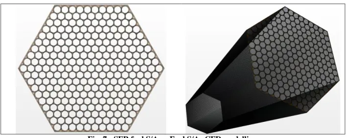
First computations (with CFD code such as STAR-CCM+) of an SFR fuel S/As are based on a very detailed meshing of the flow field around the pin bundle. To do this, the fuel S/As is firstly divided into a set of axial slices in order to decompose the domain into 2D regions, which are radially modelled in detail by CFD (Fig. 6).
Fig. 6 SFR fuel S/As – Slice CFD modelling
Once axial slices have been created, 3D S/As is modelled by connecting the axial slices (Fig. 7). Time T_Na_hot_spot
Fig. 7 : SFR fuel S/As – Fuel S/As CFD modelling
2.4.2
Some
resultsThe sodium coolant mass flow rate is not uniform in the flow sub-channels surrounding the fuel pins. As a consequence, there are strong temperature variations around the fuel pins that give rise to local hot spots at locations of deficient coolant supply, such as wake of the spacer wire.
These hot spots can modify the flow regime and affect the strength of the clad. As the clad is the first layer of defence, such temperature heterogeneities could influence the life of the fuel pin and also have direct bearing on the reactor safety. Hence a detailed study at the level of S/As is necessary to study these hot spots.
Temperature and velocity near outlet region of the rod bundle, around the central zone are displayed on Fig. 8. The high radial temperature fluctuations existing around the spacer wire indicate that the spacer wire generates, at the pin contact, local hot spots of a few degrees downstream with respect to the spacer wire.
Fig. 8 : Local thermal-hydraulic fields
3. CORE STEADY-STATE THERMAL-HYDRAULIC CONDITIONS 3.1 Numerical Analysis Needs
The main objective is to determine for all S/As in the core, their steady-state thermal-hydraulic conditions, with specific objectives, such as the achievement of a target mean outlet core temperature under sodium and pin cladding temperature limitations.
3.2 Flow Rate Management 3.2.1 Total core mass flow rate
SFR total core mass flow rate, Q_TOTAL_CORE, is deduced from mean inlet (for example 400°C) and mean outlet core temperatures (for example hot pool plenum at 550°C), associated to the thermal power of the SFR under consideration (around 1500 MW).
Several percent of Q_TOTAL_CORE, correspond to the by-pass flow Q_LEAKAGE, corresponding to the leakage at the bottom of the subassemblies. The rest, Q_S/As, is fed to the S/As by forced convection. A part of Q_S/As is dedicated to specific S/A families, such as Absorber (ABS), part of the Steel Reflectors (SR) and Internal Storage (IS). For these, flow rates (Q_Abs, Q_SR and Q_IS) are designed, taking into account specific design criteria, especially preservation of maximum cladding temperature within a given limit.
The remain part Q_FUEL can be used to cool the fuel S/As, and is deduced from balance equation: Q_FUEL = Q_TOTAL_CORE – (Q_ABS + Q_SR + Q_IS) – Q_LEAKAGE (1)
3.2.2 Fuel S/As flow rates
From a design point of view, one main target is to obtain fuel S/As outlet temperatures as uniform as possible (in nominal flow condition), in order to optimize the core loading characteristics. As the radial heat power profile is not uniform in the core, the radial distribution of fuel S/As mass flow rates must be adjusted.
For practical reasons, the fuel S/As flow management is done by dividing the fuel S/As between a restricted numbers of flow zones: all the assemblies of a given flow-zone are fitted in order to adjust their mass flow rate to a common value. Fuel S/As flow rates determination is done:
To respect the equation (1), in order to obtain the required mean outlet core temperature (550°C for example).
To maintain the hot-spot pin cladding temperature (in all fuel S/As) within a given limit; at present, this considered limit is 620°C (without uncertainties).
To flatten the S/As mean outlet temperature distribution, T_Out_Na, in order to minimize “Na hot spots”; it is realized by limiting T_Out_Na discrepancies in the core to a limit value of 50°C.
3.3 Using Trio_U MC within an Optimization Process
Determination of flow zone number and corresponding mass flow rate is done with Trio_U MC application. Given the constraints above, numerous fuel S/As flow rate distributions are conceivable (several thousands). Trio_U MC contains a simple heuristic that can compute, given a flow zone number
and a target core flow rate, a flow zone distribution minimizing the hot-spot pin cladding temperature while avoiding excessive S/As outlet temperature discrepancies.
Then, an optimization process allows choosing between all these distribution possibilities, the one which:
Maximizes the margin of the core hot-spot pin cladding temperature to the 620°C limit.
Minimizes sodium outlet temperature discrepancies.
Maintains a reduced flow zone number.
3.4 Some Results
For present SFR cores, less than 10 flow zones are sufficient to reach the objectives stated above: in the example of Fig. 9, each color apart from dark-blue (which denotes fuel-free S/As) corresponds to a flow zone.
Fig. 9 SFR core – Flow management design example
As the flow rate management is defined, Trio_U MC allows one to access radial and axial thermal-hydraulic fields at core level (Fig. 10 – left), at fuel S/As level, down to individual sub-channels and associated pins (Fig. 10 – right).
Fig. 10 SFR core – Sodium and pin clad radial temperature distributions
4. HEXAGONAL WRAPPER TUBE TEMPERATURES 4.1 Numerical Analysis Needs
Another design requirement is the knowledge of hexagonal wrapper tube temperatures for thermo-mechanical analyses. This information requires a good evaluation of the inter-wrapper flow behavior and the temperature field in this region [2].
The inter-wrapper zone may be fed by a by-pass flow adjusted at the bottom of the S/As: it is also traversed by recirculation loops to and from the hot pool plenum. Due tothe radial pressure profile imposed by the Above Core Structure atthe core outlet, hot sodium can penetrate downwards from the core outlet region into the inter-wrapper region, and then interact withthe (cold) by-pass flow before returning upwards to mix with the main core outlet flow.
Heat transfer with the hexagonal wrapper tubes, heat transfer with the outer core baffle and buoyancy effects must be taken into account in the inter-wrapper flow analysis.
4.2 MC2 Model in Trio_U Code
The numerical analysis of hexagonal wrapper tube temperatures requires a global core modelling to determine the temperature distributions and the influence of the inter-wrapper flow. To reach this objective, a 3D model of the complete core is used, with the sub-channel model for S/As and a 3D modelling of the other physical components. The Trio_U MC2 code couples:
The MC application described before, for each S/As.
A 3D modelling with CFD Trio_U of the inter-wrapper zone (Fig. 11 – left) and of the hot pool plenum, with the Above Core Structure (Fig. 11 – right).
Fig. 11 Trio_U MC2 code – Thermal-hydraulic modelling
Thus Trio_U MC2 can be used to simulate the local thermal-hydraulic behavior of the inter-wrapper zone under the influence of the complex global flow
s
between the core, the Above Core Structure and the hot pool plenum. An example of Trio_U MC2 computation for present SFR core (in nominal operating operation) is shown in Fig. 12: the different sodium flows in various areas are represented by little black arrows, with corresponding sodium temperature (in color).Fig. 12 Trio_U MC2 code – Sodium flow in SFR core
Above Core Structure
Inter-wrapper CFD Trio_U
Hot pool plenum CFD Trio_UHot pool plenum
Above Core Structure
The hexagonal wrapper tube temperatures depend on the sodium temperature within the S/As and on those in the corresponding inter-wrapper region; to obtain sufficiently converged results, it is necessary to simulate several hundred physical seconds.
In Fig. 13, an example of SFR core radial distribution of hexagonal wrapper tube temperature is shown. These results are then used in the analysis of the static mechanical equilibrium of the core.
Fig. 13 Trio_U MC2 code – Hexagonal tube temperature radial distribution in SFR core
5. CONCLUSIONS
SFR core thermal-hydraulic analyses lead to:
The thermal-hydraulic fields in individual fuel S/As: either by a sub-channel approach, implemented in the Trio_U MC code, in order to determine the sodium and cladding temperatures inside the bundle, or by a refined CFD model, in order to compute local sodium flows and to determine the effect of the helical wires.
The core permanent thermal-hydraulic conditions: these require the determination of the number of flow zones and of their corresponding flow rates (flow rate management) in order to access the radial and axial distributions of each thermal-hydraulic field at local level within the core.
The hexagonal tube temperatures: the “Trio_U MC2” code coupling associates the sub-channel S/As approach (Trio_U MC) and a 3D CFD model (Trio_U) of the inter-wrapper gaps and of the hot pool plenum, with the Above Core Structure.
For each of these items, the CEA relevant numerical tools have been presented as well as some examples of computations
.
A validation process is currently underway with comparisons of code predictions to measured data from several reactor experiments.ACKNOWLEDGMENTS
The authors express their sincere and grateful appreciation to P. SCIORA and P. LAMAGNERE (from CEA Cadarache) that provided thoughtful reviews and useful suggestions for this work.
REFERENCES
1. A. Saxena, “Thermal-hydraulic numerical simulation of fuel sub-assembly for Sodium-cooled Fast Reactor”, PhD. Thesis, Aix-Marseille University (2014).
2. D. Tenchine, “Status of Trio_U code for sodium cooled fast reactors”, Nuclear Engineering and Design, Volume 242, pp. 307-315 (2012).
3. M.S. Chenaud, “Computational thermal hydraulics schemes for SFR transients studies”, NURETH 16, USA, Chicago, August 30-September 4, project of paper 13084 (2015)
4. G. Geffraye, “CATHARE 2 V2.5_2: A single version for various applications”, Nuclear Engineering and Design, Volume 241, pp. 4456-4463 (2011).
5. R. Lavastre, “State of the Art of CATHARE Model for Transient safety Analysis of ASTRID SFR”, Proceedings of NUTHOS-10, Okinawa, Japan, December 14-18, Paper1069 (2014).