HAL Id: hal-02263442
https://hal.archives-ouvertes.fr/hal-02263442
Submitted on 4 Aug 2019
HAL is a multi-disciplinary open access
archive for the deposit and dissemination of
sci-entific research documents, whether they are
pub-lished or not. The documents may come from
teaching and research institutions in France or
abroad, or from public or private research centers.
L’archive ouverte pluridisciplinaire HAL, est
destinée au dépôt et à la diffusion de documents
scientifiques de niveau recherche, publiés ou non,
émanant des établissements d’enseignement et de
recherche français ou étrangers, des laboratoires
publics ou privés.
USE OF MODELLING METHODS AND TOOLS IN
AN INDUSTRIAL EMBEDDED SYSTEM PROJECT:
WORKS AND FEEDBACK
Anthony Fernandes Pires, Stéphane Duprat, Tristan Faure, Cédrik Besseyre,
Jack Beringuier, Jean-François Rolland
To cite this version:
Anthony Fernandes Pires, Stéphane Duprat, Tristan Faure, Cédrik Besseyre, Jack Beringuier, et al..
USE OF MODELLING METHODS AND TOOLS IN AN INDUSTRIAL EMBEDDED SYSTEM
PROJECT: WORKS AND FEEDBACK. Embedded Real Time Software and Systems (ERTS2012),
Feb 2012, Toulouse, France. �hal-02263442�
USE OF MODELLING METHODS AND TOOLS IN AN INDUSTRIAL
EMBEDDED SYSTEM PROJECT: WORKS AND FEEDBACK
Anthony Fernandes Pires
1, Stéphane Duprat
1, Tristan Faure
1, Cédrik Besseyre
2, Jack Beringuier
1,
Jean-François Rolland
11: Atos, 6 Impasse Alice Guy, B.P. 43045, 31024 Toulouse Cedex 03 2: Airbus Operations S.A.S., 316 route de Bayonne, 31060 Toulouse Cedex 9
Abstract: In a context where critical embedded systems
are more and more difficult to design while ensuring high safety requirements and a non-ambiguous specification, Model Driven Engineering offers opportunities to address such challenges and to share information efficiently in a project.
This paper presents the use of such an approach in an industrial software project concerning an embedded system for aeronautics. We describe the language used to model the software, a subset of UML/SysML allowing the representation of synchronous concepts and we focus on the functionalities used for the project in the TOPCASED framework, to derive substantial benefits from the modelling. We also present feedback from the project teams about the use of this approach in this kind of project.
Keywords: UML/SysML, TOPCASED, Model Driven Engineering, embedded system, industrial context.
1. Introduction
In aeronautic, space and automotive fields, critical embedded systems are more and more subjected to high safety requirements and complexity increases. It becomes more difficult for industrial actors to specify such systems, while ensuring the quality and the non-ambiguity of the specification. So an important verification effort is needed during the development phase to avoid errors and fix ambiguous requirements.
Model Driven Engineering (MDE), which has had real success during the last few years, allows designers to deal with these constraints and also provides, in an environment of extended enterprise, an efficient way to exchange and share information between partners.
In our case, we took advantage of a MDE approach for the software specification of a part of one of our embedded system project. To answer our needs, we chose, as modelling language, a subset of the UML standard (Unified Modelling Language) [1], close to the SysML language (System Modelling Language) [2], both defined by OMG (Object Management Group) and we relied on the TOPCASED framework (Toolkit in OPen source for Critical Application & SystEms Development) [3], support for the development of critical embedded systems and the use of MDE.
First we propose in this paper to present the context of the project. Then, we present all the works that have been made and functionalities that have been used in order to provide to project actors a way to derive substantial benefit from Model Driven Engineering. Furthermore, we propose to review the feedback on the use of such an approach in an industrial context and present the potential benefits that aren’t already exploited. We finally conclude on the approach and its potential future in other projects.
2. Context
2.1. Global description
The concerned project is an aeronautic project on an embedded avionic system which has the particularity to be more complex than the common project that our teams have the habits to deal with. Here, we understand complexity in the way that the software has such a huge size that a non-ambiguous specification is very difficult to obtain. It is all the more difficult that the project is realized by multiple actors divided into different locations and so the need to share information efficiently is very strong.
It is the reason why the teams decided to use Model Driven Engineering supporting by UML/SysML language to help them in their task. They deployed this method on a subset of the project, which is particularly complex to specify.
Moreover, our work concerns only one step of the development phase of the project: the specification. Those limitations can be explained by the fact that UML/SysML was never used on this kind of project in our context and so we need to gain confidence in the method, before deploying it on a full development cycle.
2.2. The synchronous aspects
The subset of the concerned project is a software for the management of avionic components. The work of the project teams is to specify, to design, to develop and to test this software.
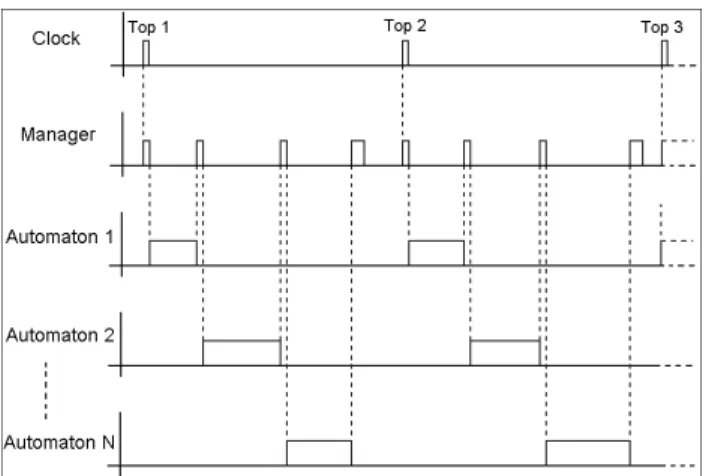
The software is composed of a manager which supervises components, and more precisely the applications of these components. They are expected to work in a synchronous
way, i.e. we know when a task begins and ends for each component.
Each component application is represented by an automaton or more precisely a state machine. The running of the software is governed by a clock. At each clock tick, that we called a cycle, all automata are called in sequence and each of them realizes one given task. It is the role of the manager to ensure that each automaton is called in sequence: it calls the first automaton and when this automaton finishes its task, it waits for the next cycle and the manager can call the next automaton. We only model the case where all automata finished their tasks in one cycle. In reality, if the automata do not finish their tasks between two clock ticks, all the software is stopped. The details of the expected behaviour are visible Figure 1.
Figure 1: global behaviour of the software
2.3. External constraints
The project is subject to external constraints from the domain and from actors of the project.
The aeronautic domain is ruled by norms which allow certifying the quality, the safety and the efficiency of its systems and software. This need of certification is one of the major constraints of the project. In aeronautics, the DO-178B norm [4] defines guidelines for the software production in avionics systems in order to obtain this certification. It describes, for different Development Assurance Level (DAL), the goals to achieve and the documents to produce at each development step. Our project is subjected to this constraint, so the project actors have to deal with these expectations during all the life cycle of the project.
Furthermore, we are in a context of client and sub-contractor. The project was created by Airbus, international aircraft manufacturer, which imposes specific constraints for the development. For confidentiality reasons, we will not detail them but we keep in mind that they exist. The project is realized by Atos, an international information technology company. Atos has the role of subcontractor. Note that we
distinguish two kinds of teams in Atos for this project: the project teams that will realize the project, and the Methods & Tools team that will support the project teams by providing them methods and tools.
3. The modelling language
3.1. UML/SysML, basis of our work
The UML language is a standard for the representation of software, defined by OMG and it is largely use. The SysML language is another standard for the representation of systems of systems. It is an extended subset of UML. In our case, the subset that we defined is a subset of UML that is also contained in the subset used for SysML language, that’s why we speak of UML/SysML language in this paper.
The use of UML/SysML was inducted by the context and a previous project team work. Indeed, they had a need for representation for their textual requirements. They already did textual specification but they were too complex to be exploited; so it was decided to use representation in the specification. They used a UML modeller in this purpose but the problem was that they did not really have formalism: they used modelling as simply graphical representation. That is why they appealed to the Methods & Tools team to accompany them in their approach and to formalize the use of the UML/SyML language.
The work did in that part consists in the definition of a subset of the UML/SysML that was restricted to the needs of the concerned subset of the project and that allowed the representation synchronous aspects of the targeted system.
3.2. The definition of the subset
We tried to limit the concepts of UML/SysML language to the specific needs of the project and to synchronous constraints. In fact, UML/SysML language is more adapted to asynchronous behaviour and it was a real challenge to represent a synchronous one. Our work was regrouped in guidelines in order to communicate them to people in charge of the modelling. The guidelines describe the useful concepts, how to use them and also patterns for the description of synchronous behaviour. For this paper, we focus the presentation of our work on five major issues encountered during the definition of our subset for the software specification.
First issue: the component representation
It is the first problem to think about for our modelling: how to represent our software and its behaviour?
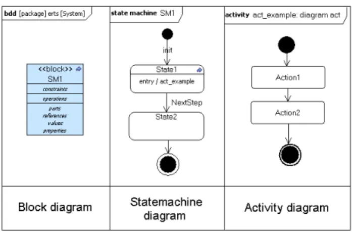
For our needs, we identify three diagrams to use:
• Block diagram: it is a diagram from the SysML language, it permits here to only represent the structure of the software and the structural relations between each of its components. A
block can also be used to represent service (factorization of operations used by components), external services or data type.
• StateMachine diagram: it represents behaviour thanks to states and transitions. It is the heart of the specification. In our case, when it is attached to a block, it corresponds to the behaviour of the component represented by the block. This is what we called an automaton.
• Activity diagram: it represents the details behaviour of a state in a state machine diagram. It is composed of actions and transitions. Each action can be the call of an operation, the call of a more refined behaviour (call of an activity by an activity) or an opaque action, which corresponds to an action that we can’t refine more.
A simple example of each diagram is given Figure 2.
Figure 2 : example of the 3 used diagrams
These are the only three diagrams that we actually need for the software specification. Moreover, in these three diagrams, we limit the use of some concepts to be compliant with synchronous constraints of the software. That is what we will see in the next issue.
Second issue: the cycle management of automata
According to the expected behaviour of the software presented Figure 1, we have a global manager that allows, at each cycle, to run a sequence of automata, representing the behaviour of each component of the software. During one cycle, each automaton has to realize one action, or a limited number of actions, before hand over to the next automaton. To obtain that behaviour, we define a pattern for the representation of state machines.
Like we presented previously, the state machine, or automaton, is composed of states and transitions. Our purpose here is to limit, at each cycle, the evolution of automaton to one or to a limited number of state(s). To realize that, we base our subset on the notion of events and run-to-completion, defined in the UML specification [1].
In a state machine, the transitions between each state can have three major properties:
• A trigger: the crossing of a transition is always run by a trigger. That trigger is an event, explicit or not. When the crossing of the transition is triggered, the occurrence of the event is consumed. In our case, to ensure the step-by-step functioning of the state machine, we define for each transition a trigger representing by a unique event, a CallEvent that we called NextStep in our subset, specific to the automaton.
• A guard: it is a condition for the crossing of a transition. Although a transition is triggered, it can only be crossed if it satisfies the guard that may be defined. In our case, a guard is only a textual condition, useful for the understanding of the specification.
• An effect: the crossing of a transition can have an effect. In our case, we limit the definition of effect to temporal negligible actions to be sure that this effect will not block the state machine evolution.
It is this definition of a unique specific event as the trigger of all transitions that will ensure the step-by-step functioning. Indeed, the UML specification defines the notion of run-to-completion for the processing of event by state machine. It ensures that the processing of an event occurrence can only be triggered if the processing of the previous occurrence is finished. The processing of an event occurrence represents the crossing of the transition that it triggered and the end of the processing of all the synchronous actions (not necessarily the asynchronous one) defined in the targeted state.
For example, let’s describe the common functioning of an automaton during one cycle: we consider that during one cycle, when the automaton is called, the NextStep event is generated; when it is generated, it is captured by the state machine that will allow the crossing of one transition; the crossing of the transition will place the state machine in a new state and starts the processing of the actions defined by this state; when the state finishes all the processing of its synchronous actions, it is ready to cross its existing transition, but in our case it is blocked thanks to the trigger, waiting for the generation of a new occurrence of the NextStep event that will occur in the next cycle. Even if our pattern is based on the definition of this unique specific event, there is a particular case that can appear in our representation: the completion event. We said that the crossing of a transition is always run by a trigger, an event explicit or not. In our case, we have an explicit event, NextStep, but we can also have the need to define no trigger between two states. In this case, we implicitly define a completion event as the trigger of the existing transition. A completion event is an event that is automatically generated at the end of all the processing of the state’s actions and will automatically trigger the
crossing of the existing transition if this one has no trigger defined. We will see the use of this particular event in a next issue.
So, the solution to ensure the step-by-step functioning of the automaton is:
• A unique specific CallEvent defined for all transition triggers between states that may occurred during different cycle
• Only define time negligible action for the effect of a transition
• The activities of the states must be synchronous We have seen how to manage the run of an automaton for one cycle. But this functioning is based on a hypothesis: a state only does synchronous actions. This is what will guarantee that no asynchronous actions are running when the next automaton is called and so preserve the expected behaviour of the software. So, the next problem to solve is to ensure that the behaviour of each state of the automaton is synchronous.
Third issue: the synchronism in an automaton state
An automaton state can have three types of defined actions, all represented by activities:
• Entry behaviour: behaviour executed when the state is entered. Its processing is completed prior to all over actions in the state.
• Do Activity: behaviour executed while being in the state. It finishes by itself or when the state is exited.
• Exit behaviour: behaviour executed when the state is exited. It is executed to completion only after the others actions of the state are finished. In our case, we restricted the definition of activities in the state in the entry behaviour only. In this condition, we ensure that the actions of the state are always completed at the end of the run-to-completion processing and so we ensure the synchronous behaviour of each state.
Furthermore, we limited the definition of activity in a state to activity that can be done in one cycle and in a synchronous way too. That is why, like explained previously, we banned the use of all possible asynchronous actions (like SendSignalAction for example) from the use of activity diagram.
In this way, we can guarantee a step-by-step functioning of each automaton and so the expected cycle management of automaton.
We can resume the pattern for this issue as follow:
• Only define activity in the entry behaviour of a state
• Only use CallOperation action, CallBehavior action and Opaque action in activity diagram
Fourth issue: the sequencing of automata
This is one of the major issues of the software representation. The goal is to call, at each cycle, each automaton in order to process their task one after the other in a predefined sequence. To ensure that behaviour, we define a pattern based on the notions of Operation and CallOperation Action.
First, we described previously that each component of the software is structurally represented by a block and its behaviour is represented by an automaton (state machine) which is attached to this same block. Now, we define for each block an operation. This operation, once called, will generate a Call Event, named NextStep in our case, which will make the attached automaton evolve to one step. This is the expected behaviour that we presented previously. Secondly, in order to realize the call the operation, we rely on a CallOperation Action defined in an activity. This activity is defined in the state machine representing the global manager behaviour of the software. It is this global manager which is in charge to guarantee the call sequence of the different automata, like described Figure 1. The activity is composed of numerous CallOperation Actions that will call the operation of all the different blocks of the modelling software, in a defined order.
Finally, the expected processing is the following. At each clock tick, the behaviour of the global manager is processed. It runs the activity defined below. The first CallOperation Action is called. It will generate the NextStep event that will make the given automaton evolve. The particularity of a CallOperation Action is, if defined as “synchronous”, to be blocking while the processing started by the call of the operation are not completed. So, the activity cannot call the next CallOperation Action while the previous automaton has not completed all of its processing, processing triggered by the CallOperation Action and more precisely the generation of the event thanks to the call of the block operation. So it permits to obtain the sequenced call of each component.
To summarize, we can describe the pattern as follow:
• An operation for each block
• A CallOperation Action defined “synchronous” in the activity of the global manager that will permit the call of the block operation
• The link between the CallEvent NextStep of the block automaton and the operation of the block
Fifth issue: the behaviours encapsulation
Another issue is the management of the complexity of the software specification. In fact, the use of the modelling was decided because of the difficulty of the textual specification to cope with the complexity of the software. With the modelling, it is easier to realize the specification, and more precisely to structured the modelling itself.
In the subset that we defined, we authorize what we can call the encapsulation of behaviours. The user can, for a reason of visibility or factorization, define an automaton that will describe a specific behaviour. This automaton can be reused by other automata and be called in a special state, named the submachine state.
The submachine state is a state which references a state machine. It is possible to enter a submachine state by what is called entry points, (specific entry in the referenced state machine) and can be exited by exit points (specific exit in the referenced state machine). In our case, we limit as much as possible the number of entry points at only one, in order to limit the complexity.
Another specific state for the definition of more refined behaviour is the composite state. It allows refining the behaviour of a state in the same state machine.
The use of submachine state implies the use of a particular event that we talked previously: the completion event. Indeed, the existing transitions of a submachine state have no explicit trigger defined. This particularity can be explained easily: the transition targeting an exit point in the state machine referenced by the submachine state already has an explicit trigger defined. The crossing of such transitions triggers the exit of the submachine state and so triggers the crossing of the exited transitions of this state. So it is not necessary to test the occurrence of the same event twice for exiting the same state.
It is also possible to encapsulate activity thanks to the CallBehavior Action.
So the solution for the behaviours encapsulation is:
• Use of submachine to reference state machine in order to factorize behaviour or the visibility of the modelling
• Use of composite state in order to refine the behaviour of a state
• The transitions exiting a submachine state is triggered by a completion event
• The states and transitions in a state machine referenced by a submachine of a composite state follow the same rules defined previously
Other issues
Other rules and patterns are available in our subset but we will not detail more of them in this paper, the major concepts that allow the specification have already been described. All these definitions have been regrouped in guidelines for the use of the project teams.
4. TOPCASED, support for our use of Model Driven Engineering
The definition of the formalism used for the modelling represents the prior and one of the most important works for the use of MDE. But the needs of the project teams are
not limited to the definition of this formalism. They also need tools to accompany them in their use of the modelling. For our project, the choice naturally felt on the TOPCASED framework.
The TOPCASED framework is an open-source platform for the development of critical embedded systems. It was initiated in 2004 in Toulouse by a consortium of many industrialists and academics. It is based on the Eclipse environment, promoting the creation and the addition of functionalities by the community. It allows activities of modelling, requirements analysis, model simulation, tests, validation, code and document generation, etc…
In our project, it was mainly used for the modelling activities thanks to its UML/SysML modeller. Furthermore, during the life-cycle of the project, other needs appeared and the teams started to think how derive benefits of the modelling thanks to the TOPCASED Framework.
So, another use of the TOPCASED Framework was for the requirement management. Indeed, like we said previously, textual specification had already been created but they were too complex to be exploited, that is why project teams decided to move to MDE. Once the modelling phase achieved, the teams needed to link textual requirements to the model and to ensure the traceability. For this task, the teams used TOPCASED Requirement[5]. This tool is a solution integrated in the TOPCASED framework which allows users to import textual requirements into models and to create easily traceability links between requirements and model elements.
Once requirements linked to model, one another benefit that appeared was the document generation from modelling. Indeed, TOPCASED integrated a tool for this task, named GenDoc2. GenDoc2 is an EPL project, which uses EMF and Acceleo M2T technologies, in order to produce documentation from a model and a template document. It’s a generic tool so it can be configured to generate specific document compliant with any documents template coming from standard. It is available to download on the Eclipse marketplace (http://marketplace.eclipse.org/content/gendoc2). In our case, it was used to generate the SRD (Software Requirements Data) document, document asked for the certification of the software according to the DO-178b norm. A specific template has been developed and the generation has been performed on the model and its linked requirements.
But the use of specific functionalities is not the only benefits derive of the modelling and the TOPCASED framework. For example, the users have derived benefits from the modeller for another use than modelling. Always in accordance with the DO-178B norm, they have to create a document named the Software Verification Cases and Procedures (SVCP). They easily succeed in creating this document by reusing the modelling for its creation
and the definition of verification cases. No tools have been developed for this activity, but we can think for the future about the automation of the method and the generation of this document from the model.
Furthermore, some of these tools have been adapted for particular needs of the project team and others tools, more confidential, have also been developed to answer specific needs of the project. It is important to notice that these adaptations and development have been realized in parallel with the project, so the project teams had to deal with this constraint too.
5. Project teams feedback
5.1. The capitalizing on feedback
In our context, it is not a common way to use UML/SysML for the specification of this kind of project. So there is a real need to capitalize on feedback of its use. We did that work by interviewing members of the project teams who are able to work with these specifications during the project.
Every interviewed actor already had some knowledge on UML and some of the actors had already worked on aeronautic embedded system project. We were able to distinguish three different kinds of feedback: what were the benefits of the use of MDE, what were the limits and what can be improve.
5.2. The advantages of the modelling
One of the most recurrent advantages expressed by users is the visual benefit of the modelling. It was the main goal of this specification modelling to be more expressive and intuitive than the textual specifications and it seems to have fulfilled that commitment. For example, one of the project teams did an informal test: they gave the two types of specification (textual and modelling) to two different people coming on the project; the result is that the modelling has been more appreciated than the textual specification. It seems very important for the users to gain on the expression and the possibility to navigate easily in the modelling, thanks to the TOPCASED Framework, has been also really appreciated. That gain in expression and intuition allowed new actors of the project to begin more quickly and more easily on the project.
But there are also some warnings: some users think that this visual benefit will not be so great if the project would be more common and less complex.
Another benefit is the gain in communication and coordination. In fact, users found that it was easier to communicate between project actors, like between people in charge of specification and designers. It is also easier to organize tasks between project actors: the modelling allows working on a part of it without knowing precisely
the others parts. So, it is easier to allocate the different tasks of the project with low investment.
The possibility to derive benefits from the modelling for the other step of the development cycle of the project was also reported. For example, during the implementation phase, the users manually used patterns from the modelling for the code. This possibility allowed them to make the task more easily. Another example, appeared during the testing phase, it is that the users have been able to propose new testing strategy that permit to verify automata more independently, deriving benefit from the expression of the modelling. It is almost too soon to draw conclusions of the benefit of this new strategy but we can already see that the use of modelling in an upstream phase of the development process can offers new possibilities for project teams.
Furthermore, the possibilities to use tools in the TOPCASED framework to answer the specific needs of the users were also well received. The modelling phase is made with the TOPCASED modeller, so being able to derive help for other phases of the project directly with associated tools in the TOPCASED framework was seen by the user like a gain in adaptability. For example, they really appreciate the coherence inducted by the documentation generation, coherence between the modelling and the different textual documents generated.
5.3. The limits of the modelling
The major disadvantage is the size of the modelling language. Indeed, in our project we limited the use of UML/SysML to a subset adapted to our needs. The number of concepts of the UML/SysML is huge and is sometimes subject to interpretation and that is what happened in our subset. Some interviewed users think that the interpretation problems come from the fact that users thought that their knowledge of UML will be sufficient to use our subset but in reality, we restricted some concepts of the language to particular use, like the synchronous aspect. Another hypothesis emitted by some users is that setting this methodology was too hard to succeed in one time. In fact, whatever is the real reason, they encountered some ambiguity in the use of the methodology. The result of these ambiguities is a large number of duplicate of code during the implementation phase. But, after seeing the problem and insisting on the concepts of methodology guide, they observed, not only the correction of the preceding problem but a gain on the number of code lines that they generated as well. From our point of view, we think that these problems of ambiguity can be due to a wrong strategy of communication of this document to the users or the wrong adaptation of the document for the targeted audience.
Another limit emitted by the team is that the method and some tools have been developed in parallel with the project. So there was an experimental side that, although it was beneficial to the teams, it cost some setback. Other
limits have been expressed on the tools. One is that sometimes, there is too many information on the screen for the task that they are doing. The other is on the UML/SysML editor used for the modelling. The editor available takes all the concepts of UML/SysML Language but in our case, we only use a subset of the language. So it was at the charge of the user to decide what concepts to use or not for the modelling. Thanks to that feedback, it will be possible to think about some improvements on the tools for the future.
A last limit is reported by the users. It concerns the fact that the UML/SysML modelling is not used on all the process. For example, the design phase is realized with another modelling language. The interviewed users reported that it was a kind disconcerting and frustrating to have to go from a formalism to another.
5.4. The way to improve the method
The interviewed users did not only report the advantages and the disadvantages of the use of MDE. They also emitted recommendations for a future use in such a context.
The first recommendation is to use the modelling method on all the project cycle. In our case, we only use it on the specification phase and we derive benefits for the other phases. The passing between different modelling languages or methods in a same process is tedious. Moreover, if we use the same modelling approach on all the process, we may be able to derive other benefits. For example, we may think to the possibility to generate code or pseudo-code from upstream modelling, idea that is not currently possible but which was been emitted by the interviewed users.
The second recommendation is to be able to verify the model in an upstream step. How to have the certitude that what we model is correct in comparison with the expecting reality? Today, this certitude is hard to obtain by a human because of the complexity and the precision of the modelling. So, we can think for the future to solutions of formal verification or simulation in order to get more confident in the model and to reduce costs on tests or problems reported in downstream phases.
The last recommendation is to define at the very beginning of the process, the modelling formalism and the tools that will be used. Like we see previously, project teams reported that, although the tools and formalism was beneficial to them, they also had some problems because the works on methods and on some tools was done in parallel. So maybe we can think to a formation on the formalism in an upstream phase of the process or more adapted methodological guidelines.
6. Conclusion
The subset of the global project which was treated was very complex and subject to strong constraints. From our
point of view, it was seen as a pilot project for us in the use of such an approach in this kind of context.
The first feedback are encouraging and show that this kind of approach can be interesting for similar projects. They showed that the gains providing by the modelling on reading, understanding and communication have reached the expectations.
The use of UML/SysML language to specify synchronous constraints was also an interesting work. Indeed, it is not common to use the UML/SysML language to model this kind of behaviour, in an aeronautic context.
The support of the TOPCASED framework proves once again the great interest of this tool for the development of critical embedded systems and software and the many opportunities it can give to project teams.
Although this project has permitted us to have a first experiment of the use of MDE in software embedded projects with so strong constraints, and more precisely the use of UML/SysML language, it is necessary to collect more feedback and to continue to work on the improvement of the method before disposing of a mature approach that may be used on future projects. The life cycle of the project is not completed and we have seen that there are many ways to improve the method, but this first work has already shown the potential of the approach.
7. Acknowledgement
The authors want to thank all the project teams for their work and particularly all the actors who accept to take time to share their experience on this project with us.
8. References
[1] OMG : “Unified Modeling Language : Superstructure”, 2005.
[2] OMG : “System Modeling Language”, 2010.
[3] P. Farail, P. Gaufillet, A. Canals, C. Camus, D. Sciamma, P. Michel, X. Crégut, M. Pantel : "The TOPCASED project : a toolkit in open source for critical aeronautic systems design”. ERTS, Toulouse, 2006. [4] RTCA : "DO-178B – Software Considerations in
Airborne Systems and Equipment Certification”. 1992. [5] R. Faudou, T. Faure, S. Gabel, C. Mertz : "TOPCASED
Requirement: a model-driven, open-source and generic solution to manage requirement traceability”. ERTS, Toulouse, 2010.
9. Glossary EMF: Eclipse Modelling Framework EPL: Eclipse Public Licence MDE: Model Driven Engineering M2T: Model to Text
OMG: Object Management Group SRD: Software Requirements Data
SVCP: Software Verification Plan and Procedures SysML: System Modelling Language
TOPCASED: Toolkit in OPen source for Critical Application & SystEms Development