HAL Id: hal-02404064
https://hal.archives-ouvertes.fr/hal-02404064
Submitted on 11 Dec 2019
HAL is a multi-disciplinary open access
archive for the deposit and dissemination of
sci-entific research documents, whether they are
pub-lished or not. The documents may come from
teaching and research institutions in France or
abroad, or from public or private research centers.
L’archive ouverte pluridisciplinaire HAL, est
destinée au dépôt et à la diffusion de documents
scientifiques de niveau recherche, publiés ou non,
émanant des établissements d’enseignement et de
recherche français ou étrangers, des laboratoires
publics ou privés.
NPC assessment in insulated DC/DC converter
topologies using SiC MOSFETs for Power Electronic
Traction Transformer
Caroline Stackler, Alexis Fouineau, Philippe Ladoux, Florent Morel, François
Wallart, Piotr Dworakowski, Nathan Evans
To cite this version:
Caroline Stackler, Alexis Fouineau, Philippe Ladoux, Florent Morel, François Wallart, et al.. NPC
assessment in insulated DC/DC converter topologies using SiC MOSFETs for Power Electronic
Trac-tion Transformer. Ee2019, Oct 2019, Novi Sad, Serbia. pp.1-6, �10.1109/PEE.2019.8923456�.
�hal-02404064�
NPC assessment in insulated DC/DC converter
topologies using SiC MOSFETs for Power
Electronic Traction Transformer
Caroline Stackler
∗§, Alexis Fouineau
∗†, Philippe Ladoux
‡, Florent Morel
∗, Franc¸ois Wallart
∗,
Piotr Dworakowski
∗, Nathan Evans
∗∗ITE SuperGrid Institute SAS, Villeurbanne, France
†UDL, Universit´e Claude Bernard Lyon 1, CNRS, Amp`ere, F-69130, Ecully, France
‡Universit´e de Toulouse, INPT, UPS, CNRS, LAPLACE (Laboratoire Plasma et Conversion d’Energie)
F-31000 Toulouse, France
§Email: [email protected]
Abstract—Power electronic traction transformers (PETT) are multilevel AC/DC on-board converters, studied for railway appli-cations to replace traditional solution with low frequency trans-formers. This paper focuses on the insulated DC/DC converter in a PETT. Three variants of resonant single active bridges (R-SAB) with 3-level NPC primaries are optimised to maximise the efficiency, under mass and dimension constraints. They are sized and compared for a 2 MW PETT on a 15 kV/16.7 Hz railway infrastructure, using 3.3 kV SiC MOSFETs and nanocrystalline C-core transformers with cast resin insulation and forced air cooling. The highest efficiency at nominal power, 99.17 %, is reached for a configuration with a 3-level full bridge NPC primary, a 2-level full bridge secondary, and a 32.1 L/49.1 kg transformer operating at 6 kHz.
Index Terms—power electronic traction transformer (PETT), solid state transformer (SST), AC-DC multilevel converter, rail-way, traction, medium frequency transformer (MFT), series resonant converter (SRC), resonant LLC converter, optimisation
I. INTRODUCTION
In trains running on AC railway infrastructures, an on-board AC-DC power converter is necessary to adapt the medium AC voltage of the overhead line to a lower DC voltage. Traction motors and auxiliaries are then supplied from the DC voltage, thanks to three phase inverters.
Traditionally, the AC-DC conversion between the catenary and the traction bus is realised thanks to a low frequency step down transformer and Si IGBT and diode full bridges inverters [1]. In the past decades, alternatives, including medium fre-quency transformers (MFT), have been investigated to replace this solution, and improve the efficiency, limited by the volume constraint on the low frequency transformer [1]–[5].
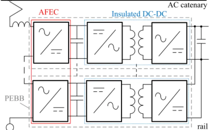
Power electronic traction transformers (PETT) require an AC/AC conversion to adapt the infrastructure frequency to the transformer frequency. This conversion can be realised with an intermediate DC stage, as depicted in Fig. 1. This topology is composed of input cascaded multilevel inverters, called active front end converter (AFEC). The AFEC is connected to the overhead line thanks to an input filter, either a single inductance or a LCL filter [6]–[8], and to intermediate DC
PEBB
Insulated DC-DC
AFEC
rail AC catenary
Fig. 1. Considered PETT topology
buses on the DC side. Paralleled insulated DC/DC converters connect then the traction bus to the intermediate DC buses. An elementary insulated AC/DC conversion stage, i.e. the set including an inverter of the AFEC, an intermediate bus and an insulated DC/DC converter, forms a power electronic building block (PEBB). Several cascaded PEBBs are required to withstand the overhead line voltage.
Compared to solutions using a low frequency transformer, either a higher efficiency under the same weight and volume constraints, or a volume and mass gain can be expected with PETTs, especially on 15 kV/16.7 Hz infrastructures. However, since the number of semiconductors is much more important in PETTs, the impact on the reliability of the converter is quite high, and holds back the development of the topology for railway applications [9].
The expected gain on the efficiency in a same volume is higher for a network operating at lower frequency. Moreover, for a higher overhead line voltage, more PEBBs are required, and the amount of semiconductors and MFTs is more im-portant. The reliability is thus intrinsically decreased, while the volume gain is limited by the voltage insulation of the transformers and the number of PEBBs. For these reasons,
PETT technologies are more promising for 15 kV/16.7 Hz infrastructure. Thus, even if the 25 kV/50 Hz railway network is more frequently used than 15 kV/16.7 Hz infrastructures, the study is focused on 15 kV/16.7 Hz applications.
When the traction chain is distributed along the train, either subframe- or rooftop-mounted, the mass and the volume of the PETT is critical. Moreover, in order to fit inside the traction case [9], not only the volume but some dimensions are constrained, especially for the MFTs. A typical layout of the traction case would be to allocate a section for the input filter, grant another part to the three phase traction inverters, and keep the remaining space of the traction case for the PETT. This last section would be divided into subsections, each corresponding to a PEBB. Every subsection would then be separated into three parts:
• a high voltage side, including the AFEC and the primary of the DC/DC converter, and the intermediate capacitors; • a volume allocated to the medium frequency transformers
and their cooling system;
• a low voltage side, including the secondary of the DC/DC converter and the traction bus capacitors. A LC filter can be added to eliminate the ripple at twice the grid frequency, caused by the single phase AC/DC conversion. The PETT structure considered here contains intermediate DC buses (see Fig. 1). The paper focuses on the insu-lated DC/DC converters. SiC MOSFET are considered in the DC/DC converters for their lower switching losses compared to Si IGBTs. In order to limit the number of semiconduc-tors, the SiC MOSFETs with the highest breaking voltages currently available on the market are considered. 3.3 kV SiC MOSFETs have thus been selected [10].
To limit the number of PEBBs, three level NPC bridges are considered for the AFEC and the primary of the DC/DC converter. The traction bus voltage is set at 1.8 kV. 2-level bridges are thus sufficient in the DC/DC secondaries. Thanks to the NPC structure of the primaries, the intermediate bus voltage can be set at twice the traction bus voltage. Since the current ratings of SiC MOSFET currently available [10], [11] are quite high for this application, half bridges can be considered to improve the reliability.
The objective of the study is to maximise the efficiency of the converter, while ensuring a minimum reliability, using cur-rently available semiconductors. The impact on the efficiency of half bridges in the DC/DC converter will be estimated and compared to full bridges. In section II, the considered DC/DC variants are presented. In section III, the methodology used to size the DC/DC converters is described. Section IV is dedicated to the application and the results. Some conclusions and perspectives close the paper.
II. CONSIDEREDPETTTOPOLOGY ANDDC/DC
STRUCTURES
In a previous study [12], four structures of insulated DC/DC converters, either resonant or non-resonant, and controlled or non controlled, have been compared. It has been shown, that,
I1 I2
Im
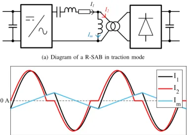
(a) Diagram of a R-SAB in traction mode
I 1 I 2 I m 0 A
(b) Current waveforms in DCM operation (magnetising inductance fixed delib-erately low to highlight the impact of the magnetising current).
Fig. 2. Resonant Single Active Bridge (R-SAB)
for this application, higher efficiencies were reached at nomi-nal power, with the so called resonant single active bridge (R-SAB) structure operating in discontinuous conduction mode (DCM). The general diagram of a R-SAB, also called se-ries resonant converter (SRC) or resonant LLC converter, is presented in Fig. 2(a). A capacitance, in series with the transformer, forms a resonant circuit, at a frequency set higher than the switching frequency, to operate in discontinuous conduction mode. To simplify the control and reduce the current for a given power, the active bridge is controlled by square waves, only two voltage levels are used as for classic 2-level R-SABs [6], [12], [13]. The NPC structure in the primary is used only to reach a higher intermediate voltage. Therefore, the clamped diodes are active only during the dead times. Typical waveforms of currents in the AC link are illustrated in Fig. 2(b).
Three variants are considered for the R-SAB:
• FB/FB: full bridges at both the primary and the secondary (see Fig. 3(a));
• HB/FB: half bridge at the primary and full bridge at the secondary (see Fig. 3(b)). In this variant, since the intermediate bus voltage is twice the traction bus voltage, the currents flowing in the MOSFETs of the primary and the secondary are almost the same, apart from the magnetising current. The losses should thus be well balanced between the MOSFETs, and easier to dissipate; • HB/HB: half bridges at both the primary and the sec-ondary (see Fig. 3(c)). In this variant, the total amount of semiconductors is optimised.
III. SIZING METHODOLOGY
In order to compare the different variants of DC/DC con-verters, each structure is first sized to maximise its efficiency at nominal power under mass and dimension constraints on the transformer. The methodology developed to optimise the
(a) FB/FB: full bridge primary and secondary
(b) HB/FB: half bridge primary and full bridge secondary
(c) HB/HB: half bridge primary and secondary Fig. 3. Diagram of the three types of R-SAB compared in the study. One bridge operating as a diode bridge, which would be the secondary bridge in traction and the primary bridge in braking.
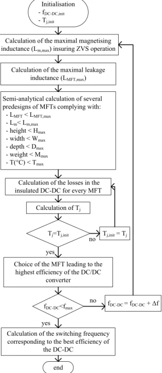
DC/DC converters and the full PETT converter has been pre-viously presented for 2-level bridges [12], [13]. The flowchart is presented in Fig. 4.
The first steps of the process are the calculations of the boundaries of the magnetising and leakage inductances of the transformer. To maximise the efficiency of the DC/DC converter, the MOSFETs are turned-on at zero voltage (ZVS). To ensure ZVS operations, a minimum current is required in the MOSFET during the switching, in order to charge and
Initialisation - fDC-DC,init
- Tj,init
Tj=Tj,init
Calculation of the losses in the insulated DC-DC for every MFT
Calculation of Tj
Calculation of the switching frequency corresponding to the best efficiency of
the DC-DC end
Tj,init = Tj
Calculation of the maximal leakage inductance (LMFT,max)
Semi-analytical calculation of several predesigns of MFTs complying with: - LMFT < LMFT,max - Lm< Lm,max - height < Hmax - width < Wmax - depth < Dmax - weight < Mmax - T(°C) < Tmax fDC-DC<fmax fDC-DC = fDC-DC + Δf
Choice of the MFT leading to the highest efficiency of the DC/DC
converter
no yes
no
yes
Calculation of the maximal magnetising inductance (Lm,max) insuring ZVS operation
Fig. 4. Flowchart of the sizing methodology of an insulated DC/DC converter
discharge the Cdscapacitances of the MOSFETs during dead times. In R-SAB operating in discontinuous conduction mode, the switched current is equal to the magnetising current. The magnetising inductance of the transformer is thus limited to ensure ZVS operation. In single active bridge mode, the AFEC regulates the traction bus voltage. The intermediate bus voltage varies when power is drawn on the traction bus. The voltage drop on the intermediate buses is linked to the impedance of the AC link. The leakage inductance of the transformer is thus limited by the tolerated voltage variation on the intermediate buses.
After the calculation of the constraints, the voltages and the currents of the transformers, a large amount of designs of transformers are generated by varying several degrees of freedom: magnetic induction, current densities, number of turns and form factors.
The classic reluctance evaluation method has been used to calculate the magnetising and leakage inductances and the parasitic capacitances, assuming a magnetic field normal to the magnetic core cross-section and an electric field normal to the conductor surface.
The improved generalised Steinmetz equation (IGSE) [14] is used to calculate the magnetic losses, for the non-sinusoidal magnetic induction. The winding losses are estimated taking into account the parasitic eddy currents caused by the high switching frequency. A model, considering skin and proximity effects in the conductors, has been developed for Litz wire in core type geometry [15]. Each voltage harmonic applied to the MFT is then used to estimate the dielectric losses thanks to the parasitic capacitances and the dissipation factor of the epoxy resin. More details of the sizing methodology of the MFTs, including the thermal calculations, are available in [12].
The MFT designs are then filtered to eliminate those not complying with the constraints (leakage and magnetising in-ductance values, weight and dimensions), or reaching too high temperatures.
The current waveforms are then re-calculated, thanks to analytical computation and validation in simulation, with the parameters of the generated MFTs complying with the constraints, to calculate the losses in the MOSFETs. Turn-off energies are approximated from [10], thanks to a second order polynomial. Turn-on losses are assumed negligible, thanks to ZVS operation. Conduction losses are calculated considering that the MOSFET on-state resistance Rds,on varies with the junction temperature as defined in [16]. Then, the calculations are iterated to reach thermal steady state in the MOSFETs for a fixed base plate temperature. The MFT design leading to the lowest losses in the DC/DC converter is eventually selected. The losses in the capacitors (resonant and DC buses) are not considered in the optimisation.
IV. APPLICATIONS
3.3 kV SiC MOSFETs [10] are investigated, for 3-level NPC bridges in the SAB primaries and 2-level bridges in the secondaries of the SABs. The intermediate and traction bus voltages are then fixed at respectively 3.6 kV and 1.8 kV. This results in eight active PEBBs and one added PEBB for redundancy, for a 2 MW PETT on a 15 kV/16.7 Hz infrastructure.
Nanocrystalline C-core MFTs, with laminated Litz wires, cast epoxy resin insulation and forced air cooling at 2 m/s, are considered. The ambient temperature for the MFT cooling is 40◦C, and the base plate of the MOSFETs is assumed equal to 75◦C.
The total weight of all the transformers is limited to 450 kg. For every MFT, the maximal dimensions have been set to ensure that the MFTs fit inside the central part of the traction
5
10
15
Frequency (kHz)
0.97
0.975
0.98
0.985
0.99
0.995
Efficiency
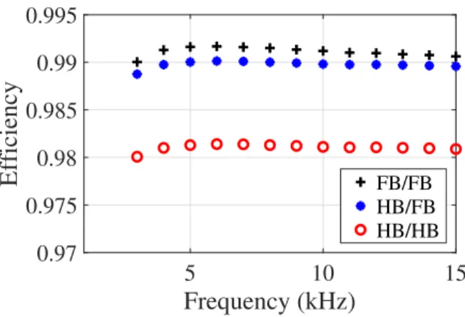
FB/FB HB/FB HB/HBFig. 5. Efficiency of the DC/DC converter at nominal power, for the MFT design leading to the highest efficiency for each frequency.
case, divided in 9, considering 8 active PEBBs and one for redundancy. The height of the transformer is limited by the fans and a minimum air channel, required to cool all the MFT and dissipate the heat, and whose height depend on the number of MFTs.
The efficiency obtained at nominal power for the best designs in the three configurations is plotted in Fig. 5 in the considered frequency range, i.e. from 1 kHz to 15 kHz. For the three configurations, a maximum is reached at 6 kHz. For lower frequencies, the dimension and mass constraints limit the efficiency of the MFT. For frequencies lower than 3 kHz, all MFT designs were too bulky for the application. For higher frequencies, the efficiency is narrowed by the frequency effects in the transformers: skin and proximity effects in the windings and increase of core losses, and the higher switching losses in the MOSFETs. However, in this DC/DC configuration, i.e. R-SAB in discontinuous conduction mode, the MOSFETs turn-on in ZVS and turn-off turn-on a low current (magnetising current). The impact of the switching losses on the global efficiency of the DC/DC converter is thus quite low.
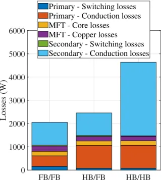
The repartition of the losses in the best designs and the DC/DC converter efficiency in the power range of the PETT are presented respectively in Fig. 6 and in Fig. 7. The highest efficiencies reached at nominal power in the three configurations are respectively: 99.17 % in FB/FB; 99.01 % in HB/FB; 98.14 % in HB/HB. However, for lower power, HB/FB and HB/HB configurations have a better efficiency. The dielectric losses are negligible and thus, not represented. The switching losses are very low thanks to ZVS operations and low current turn-off, even for switching frequency at 6 kHz. As expected, the conduction losses increase when using half bridges. Replacing a NPC full bridge by a NPC half bridge in the primary doubles the conduction losses in both HB/FB and HB/HB configurations. However, since the primary conduction losses are only 22 % of the total losses in the FB/FB configuration, the impact on the efficiency remains acceptable. When substituting the secondary full bridge by a half bridge, the conduction losses are tripled because of
FB/FB
HB/FB
HB/HB
0
1000
2000
3000
4000
5000
6000
Losses (W)
Primary - Switching losses
Primary - Conduction losses
MFT - Core losses
MFT - Copper losses
Secondary - Switching losses
Secondary - Conduction losses
Fig. 6. Losses in the DC/DC converters (one PEBB considered) at nominal power for the designs with the highest efficiency at nominal power
-1
0
1
2
Power (MW)
0.92
0.94
0.96
0.98
1
Efficiency
FB/FB HB/FB HB/HBFig. 7. Efficiency in function of the output power of the DC/DC converter
the increase of the MOSFET on-state resistance, which is related to the junction temperature rise. This makes the HB/HB configuration not attractive.
Thanks to the rather low losses in the MOSFETs, the rise of the junction temperature remains quite low, i.e. inferior to 16◦C, in FB/FB and HB/FB configurations in both primary and secondary. Liquid cooling, required in a standard traction chain with a low frequency transformer, can be replaced by forced air cooling for the power modules and the MFTs. The maintenance, quite important for classic on-board converters, can thus be highly reduced.
The numbers of semiconductors in the three configurations are listed in Table. I. Using half bridges instead of full bridges in the primary can improve the reliability and cost of the PETT,
TABLE I
SEMICONDUCTOR MODULE QUANTITIES IN THE THREE CONFIGURATIONS
(INCLUDING THEAFEC) SiC MOSFETs SiC diodes FB/FB 180 72 HB/FB 144 54 HB/HB 126 54
without highly affecting the efficiency in all the power range, and may even present a better efficiency at low power.
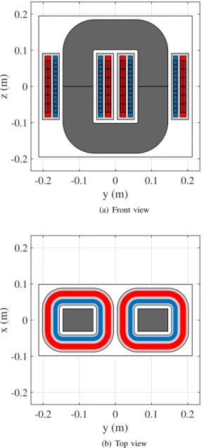
The best MFT designs are quite close in term of dimensions and weight for the three configurations. Their volume and weight are around respectively 32 L and 49 kg. Top, front and side views of the MFT designed for the HB/FB configuration are depicted in Fig. 8 and in Fig. 9. The small depth of the transformer allows it to fit inside the traction case.
V. CONCLUSIONS
Three variants of insulated DC/DC converters have been sized to maximise the efficiency at rated power under mass and dimension constraints. They have been compared, in the scope of 15 kV/16.7 Hz railway infrastructure, for a 2 MW PETT using 3.3 kV SiC MOSFETs. The lowest losses, at rated power, are obtained with full bridges in both the primary and the secondary. The efficiency at nominal power is lower with the HB/HB solution. However, the efficiency are quite close for the FB/FB and HB/FB topologies at nominal power. Moreover, the HB/FB configuration allows a reduction of 20 % of SiC MOSFETs and of 25 % of the SiC diodes, compared to a full bridge configuration.
Given the low losses, forced air cooling for the MFTs and the power modules can also be considered instead of a liquid cooling. The maintenance of the PETT could be highly improved compared to a classic solution with low frequency transformer, which requires liquid cooling.
The losses in the capacitors have been neglected in the study. However, this hypothesis has to be verified when using half bridges, as all the power of the DC/DC converter flows through the capacitors in this case. The hypothesis on losses in soft switching should be validated or disproved by soft switching characterisations on SiC MOSFETs. Special care is also required for the balancing of the mid-point of the capacitor buses in NPC or half bridge. An acoustic noise analysis should also be carried out to complete the sizing of the MFTs. The optimisation can also be improved if realised on a typical mission profile, instead of only at rated power. This could make the HB/FB solution even more competitive.
VI. ACKNOWLEDGEMENT
This work has been supported by a grant overseen by the French National Research Agency (ANR) as part of the “Investissements d’Avenir” Program (ANE-ITE-002-01). The authors also gratefully acknowledge the support provided by Alstom.
-0.2 -0.1 0 0.1 0.2
y (m)
-0.2 -0.1 0 0.1 0.2z (m)
(a) Front view
-0.2 -0.1 0 0.1 0.2
y (m)
-0.2 -0.1 0 0.1 0.2x (m)
(b) Top viewFig. 8. Diagram of the optimal design of MFT for the HB/FB configuration. Core in dark grey, primary and secondary windings in blue and red, epoxy resin in light grey.
REFERENCES
[1] D. Ronanki and S. S. Williamson. Evolution of power converter topologies and technical considerations of power electronic transformer-based rolling stock architectures. IEEE Transactions on Transportation Electrification, pages 211–219, March 2018.
[2] D. Dujic, F. Kieferndorf, and F. Canales. Power electronic traction transformer technology for traction application - an overview. In Electronics, volume 16, June 2012.
[3] B. Bednar, P. Drabek, and M. Pittermann. The comparison of different variants of new traction drives with medium frequency transformer. In 2016 SPEEDAM, International Symposium on Power Electronics, Electrical Drives, Automation and Motion, pages 1172–1177, June 2016. [4] J. Feng, W. Q. Chu, Z. Zhang, and Z. Q. Zhu. Power electronic trans-former based railway traction systems: Challenges and opportunities. IEEE Journal of Emerging and Selected Topics in Power Electronics, 2017.
[5] S. Farnesi, M. Marchesoni, and L. Vaccaro. Advances in locomotive power electronic systems directly fed through AC lines. In 2016
-0.2 -0.1 0 0.1 0.2
x (m)
-0.2 -0.1 0 0.1 0.2z (m)
Fig. 9. Side view of the optimal design of MFT for the HB/FB configuration
SPEEDAM, International Symposium on Power Electronics, Electrical Drives, Automation and Motion, pages 657–664, June 2016.
[6] C. Zhao, D. Dujic, A. Mester, J. K. Steinke, M. Weiss, S. Lewdeni-Schmid, T. Chaudhuri, and P. Stefanutti. Power electronic traction transformer-medium voltage prototype. IEEE Transactions on Industrial Electronics, 61(7):3257–3268, July 2014.
[7] R. Aceiton, J. Weber, and S. Bernet. Input filter for a power electronics transformer in a railway traction application. IEEE Transactions on Industrial Electronics, 2018.
[8] M. Steiner and H. Reinold. Medium frequency topology in railway applications. In 2007 European Conference on Power Electronics and Applications, pages 1–10, Sept 2007.
[9] R. Akli. Challenges and interests of e-transformer in railway traction system. In ECPE Workshop: New Technologies for Medium-Frequency Solid-State Transformers, Feb 2019.
[10] J. Hayes, W. A. Curbow, B. Sparkman, D. Martin, K. Olejniczak, A. Wijenayake, and T. McNutt. Dynamic characterization of next gen-eration medium voltage (3.3 kV, 10 kV) silicon carbide power modules. In PCIM Europe 2017; International Exhibition and Conference for Power Electronics, Intelligent Motion, Renewable Energy and Energy Management, pages 1–7, May 2017.
[11] J. Yamada and E. Thal. Gaining speed: Mitsubishi electric SiC-power modules. Technical report, Mitsubishi, 2018.
[12] F. Morel, C. Stackler, P. Ladoux, A. Fouineau, F. Wallart, N. Evans, and P. Dworakowski. Power electronic traction transformers in 25 kV/50 Hz systems: Optimisation of DC/DC isolated converters with 3.3 kV SiC MOSFETs. In PCIM Europe 2019; International Exhibition and Conference for Power Electronics, Intelligent Motion, Renewable Energy and Energy Management, May 2019.
[13] C. Stackler, F. Morel, P. Ladoux, A. Fouineau, F. Wallart, and N. Evans. Optimal sizing of a power electronic traction transformer for railway applications. In IECON 2018 - 44th Annual Conference of the IEEE Industrial Electronics Society, pages 1380–1387, Oct 2018.
[14] K. Venkatachalam, C. R. Sullivan, T. Abdallah, and H. Tacca. Accurate prediction of ferrite core loss with nonsinusoidal waveforms using only Steinmetz parameters. In 2002 IEEE Workshop on Computers in Power Electronics, 2002. Proceedings., pages 36–41, June 2002.
[15] A. Fouineau, M. Raulet, B. Lefebvre, N. Burais, and F. Sixdenier. Semi-analytical methods for calculation of leakage inductance and frequency-dependent resistance of windings in transformers. IEEE Transactions on Magnetics, pages 1–10, 2018.
[16] K. Sheng. Maximum junction temperatures of SiC power devices. IEEE Transactions on Electron Devices, pages 337–342, Feb 2009.