Publisher’s version / Version de l'éditeur:
Technical Note (National Research Council of Canada. Division of Building Research), 1966-07-01
READ THESE TERMS AND CONDITIONS CAREFULLY BEFORE USING THIS WEBSITE. https://nrc-publications.canada.ca/eng/copyright
Vous avez des questions? Nous pouvons vous aider. Pour communiquer directement avec un auteur, consultez la première page de la revue dans laquelle son article a été publié afin de trouver ses coordonnées. Si vous n’arrivez pas à les repérer, communiquez avec nous à [email protected].
Questions? Contact the NRC Publications Archive team at
[email protected]. If you wish to email the authors directly, please see the first page of the publication for their contact information.
For the publisher’s version, please access the DOI link below./ Pour consulter la version de l’éditeur, utilisez le lien DOI ci-dessous.
https://doi.org/10.4224/20358845
Access and use of this website and the material on it are subject to the Terms and Conditions set forth at
Ground Temperature Installations, Powerhouse, Inuvik, N.W.T.
Johnston, G. H.
https://publications-cnrc.canada.ca/fra/droits
L’accès à ce site Web et l’utilisation de son contenu sont assujettis aux conditions présentées dans le site LISEZ CES CONDITIONS ATTENTIVEMENT AVANT D’UTILISER CE SITE WEB.
NRC Publications Record / Notice d'Archives des publications de CNRC: https://nrc-publications.canada.ca/eng/view/object/?id=774484c6-ce1b-4c07-918f-bf52e742fefa https://publications-cnrc.canada.ca/fra/voir/objet/?id=774484c6-ce1b-4c07-918f-bf52e742fefa
,
' - ,
.
DIVISION OF BUILDING RESEARCH
NATIONAL RESEARCH COUNCIL OF CANADA.
TEClHlN ][CAIL
NO'JI'JE
No.
472prセpared BY G. H. Johnston CHECKED BY CBC APPROyED BY RFL
DATE July 1966
PREPARED FOR Inquiry and record purposes
SUBJECT GROUND TEMPERATURE INSTALLATIONS, POWERHOUSE, INUVIK. N. W. T.
This note has been prepared to record pertinent details of
the thermocouple cables installed in 1958 to measure ground temperatures at the Inuvik powerhouse. Certain modifications and improvements made to these installations in 1965 are also described.
Foundation piling for the powerhouse was placed to depths of about 27 ft between November 1957 and January 1958. Piling was to be placed in slurry-backfilled, augered holes but because of the very stony soils encountered, a combination of steaming and drilling was required. Concern was felt that oversteaming, which occurred at several locations, might appreciably increase the freezeback time.
At the request of Montreal Engineering Co. Ltd. (consulting engineers to the Northern Canada Power Commission (NCPC», seven thermocouple cables were fabricated by the Division of Building Research to measure ground temperatures at the powerhouse. Five cables were installed to 30 ft under DBR supervision early in March 1958 in holes drilled immediately adjacent to selected piles (within 1 to 2 ft). Two . cables were installed to 20 ft by Montreal Engineering staff late in
April 1958, in drill holes also located adjacent to selected piles.
Ground temperature observations were made on the individual cables at fairly regular intervals during 1958 and part of 1959. Only
random observations, at intervals of one month or greater, were made from 1960 to 1965. More frequent readings were required, however, in order to assess the .ground thermal regime with respect to the performance of this structure and its effect on the underlying permafrost.
Ground-temperature measurements were obtained initially with a manually-operated portable potentiometer. The sensitivity of this instrument is unsatisfactory when used with installations of long lead length and consequently of large resistance, and for this reason the thermocouple installations at the powerhouse could not be lengthened. The instrument had to be set up at each installation in turn under the powerhouse - a time-consuming and somewhat tedious operation particularly during the winter months.
A laboratory-type electronic indicator was then adapted for field use and this instrument, the sensitivity of which is not affected by normal lead lengths, was occasionally used. Although the instrument could be located outside the powerhouse, the observer required an assistant to crawl around under the building to connect the lead cable to each installation in turn.
To simplify the taking of readings in view of the increased number of observations desired, the original cables were extended by DBR ー・イウッョセ・ャ in September 1965 so all cables were brought to a common switch box conveniently located in the powerhouse crawl space, i. e., between the main floor and the false floor. All readings can now be taken in a matter of minutes using the electronic temperature indicator which is brought into the powerhouse and set up close to the
switch box.
DESCRIPTION OF ORIGINAL INSTALLATIONS
The five 30-ft and two 20-ft cables were fabricated using either PVC or fabric-covered, 20 gauge copper-constantan duplex wire. For each cable the group of wires, of varying length, were taped together and placed in a 3/4 in. dia. plastic hose which was tightly sealed at the lower end. The thermocouple wires were connected to a rotary-type selector switch housed inside a special box attached to the upper end of each cable. An extra 5 ft lead length was allowed for each cable so that the switch box could be conveniently located above the ground surface.
3
-All copper wires in each cable were connected to appropriate terminals on the rotary switch. A single copper wire connected the switch to a copper plug mounted on the switch plate. All constantans were brought to a common constantan wire which was flattened to form a washer on the switch plate. For reading, the instrument was connected to the switch box by a cable which had special terminals that mated with those on the switch plate. Each switch box was attached. to the adjacent pile and a plywood shelter constructed around it.
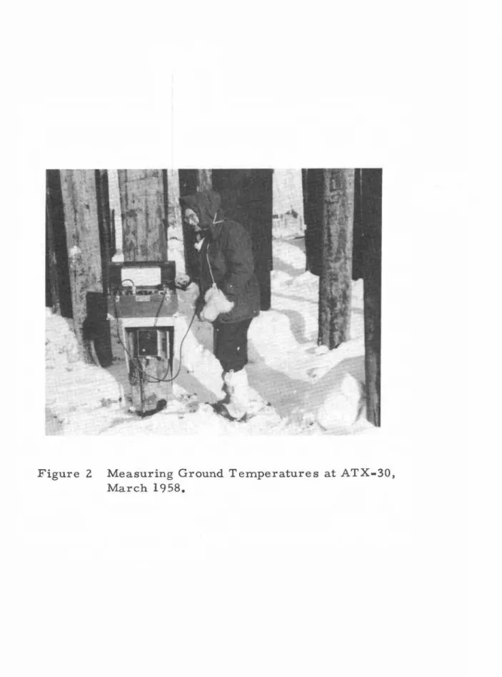
Details of these installations are given in Table I. The location of each cable is shown in Figure 1. A typical ground-temperature measurement set-up is illustrated in Figure 2.
RECENT MODIFICATIONS
To simplify and improve the measurement of ground
temperatures, it was desirable to group all switches at a convenient location, preferably within the powerhouse or the crawl space. It was agreed, following discussion with NCPC personnel at the site, that the most suitable position would be in the crawl space at pile N-lO (NCPC Pile No. 133) which is located immediately adjacent to the crawl space access door in the powerhouse floor. The following modifications to these installations were made by DBR personnel in late September 1965.
The switch and switch boxe s attached to the ends of the original individual cables were removed and varying lengths of 12 -pair multi-conductor, coppe r -constantan extension thermocouple cable were spliced on to the free ends of the ground temperature cables so that the switches could be located in the crawl space. Two types of multi-conductor cables were used; Thermo Electric "Thermo-Cable" type PPeK-12-20-DD and Shaw Flexible Tubes type M-TX-1820-01250. The individual conductors in these cables are covered with polyvinyl chloride and the bundle of conductors is wrapped with aluminum-backed Mylar tape. The cables are finished with an over -all jacket of polyvinyl chloride (Shaw) or polyethylene (T. E.). The wires of the T. E. cable are of premium grade copper and constantan and those of the Shaw cable are of standard grade. A total of 340 ft of multi-conductor cable was used.
The length of extension cable used for each installation was placed inside an appropriate length of 1/2 in. dia. black
polyethylene pipe (CGSB spec. 4l-GP-5A) and two 5- ft-long pieces of 1 in.and 3/4 in. dia. polyethylene pipe were slipped over this protective tubing before splices were made.
The splice was made by twisting and soldering the matching copper wires together and taping each connection separately. The ten constantan wires from the ground cable and ten from the extension cable were bundled together and firmly clamped using a special Marr-type constantan connector. This connection was then securely taped to the cable. The eleventh pair of wires in the extension cable was cut, twisted and soldered to make a thermocouple junction to measure the air temperature at the splice. The twelfth pair in the extension cables was cut, taped and not used for any temperature measurement.
When the splice was completed, the 1 in. dia. pipe sleeve was pulled over the splice and the end of the 3/4-in. protective pipe covering the ground cable and tightly clamped in place with about 1 ft of overlap. One end of the 3/4-in. pipe sleeve was then inserted into the opposite end of the 1 in. dia. sleeve and tightly clamped. The other end of the 3/4 in. dia. sleeve covered the 1/2 in. dia. extension cable protective pipe and was securely clamped. Details of the splice are shown in Figure 3(a).
The above procedure was used for the five 30-ft cables (ATX-27 to ATX-31), each of which had 10 thermocouple junctions. One length of extension cable was used, however, to bring the two 20-ft cables (ATX-32 and 33), which had 5 thermocouple junctions each, to the main switch box. A different splice was therefore used for these installations. A splice similar to that described above was used to connect wire pairs 6 to 10 of the extension cable to ground temperature cable ATX-33. The eleventh pair was joined to form a thermocouple junction to measure the air temperature at this splice. Where the extension cable passed installation ATX-32, a slit about 3 ft long was made in the outer sheath of the extension cable to expose the conductors. The five pairs of copper and constantan wires from ATX-32 were spliced to extension cable pairs 1 to 5 as described previously. The 1/2 in. dia. sleeve covering the ATX-3Z wires was then taped securely to the 3/4 in. and 1 in. dia. sleeves covering the ATX-32 extension cable splice. Details are shown in Figure 3(b).
All extension cables were then led to pile N-I0 and were brought up into the crawl space through holes bored in the exterior
5
-sheathing, insulation and interior sheathing of the crawl space floor. The cables were attached to adjacent piles en route (Figure 1) using conduit U - clamps; in some cases they were secured to the underside of the floor.
Six Leeds & Northrup (L. & N.) 12-point rotary-selector switches and six special copper and constantan wire-wound connectors (fabricated by DBR) were mounted in a heavy plywood box secured to pile N-I0 in the crawl space. With the exception of switch No.6, to which installations ATX-32 and -33 were connected, each installation had an individual switch. The copper wires from each cable were soldered to appropriate terminals of the switch. A common copper from the wire-wound connector mounted on the box was soldered to the appropriate lug on the switch. All constantans from each cable were clamped to a common constantan from the special wire-wound connector using a Marr-type constantan connector. Details of the cables and switching are given in Tables II and III.
COMMENTS
With the exception of cable ATX-28, which was placed 1 ft short of the desired depth, all cables were installed to either 20 or 30 ft with little difficulty in 4 1/2 in. dia. drill holes. Anomalous readings have been obtained consistently at ATX-29 which would seem to indicate that this cable might be faulty. It has been checked on several occasions, however, and found to be in good condition. The temperatures measured at ATX-29 are identical throughout the year for each depth and vary with the season, being cold in the winter and around 320
F during the summe r. During the drilling of this hole
considerable difficulty was experienced in retaining water circulation -more than 900 gallons of water were used. It was suggested that a void or cavity formed during the drilling of this hole, and that when the cable was installed it simply coiled up in the cavity at a depth of
approximately 5 to 6 ft below the ground surface. All thermocouple junctions are at about the same depth therefore and thus register the same ground temperature. All other cables appear to function properly and give reasonable results.
The depths of the thermocouple junctions for cables ATX-32 and -33 were originally noted as 5, 10, 12.5, 15 and 17.5 ft, and ground temperatures have been recorded for these depths until recently. Upon checking cable fabrication records and comparing wire-resistance
should be 2.5, 5, 10, 15 and 20 ft, as shown in Tables I and II.
The depths for the thermocouple junctions shown in Tables I and II indicate their position when installed in the spring of 1958. In subsequent years, ground subsidence and backfilling and grading of the ground surface under the powerhouse may have changed the position of the junctions relative to the surface. It is believed, however, that all depths given are within ± 0.5 ft; certainly within
±
1.0 ft of their actual position.Arrangements have been made with the Inuvik Research Laboratory to have observations made every two weeks throughout the year on the seven ground-temperature installations at the power-house. This schedule will be maintained for at least one full year, and probably two or more.
e
e
TABLE 1
INUVIK POWERHOUSE THERMOCOUPLE CABLES, ORIGINAL INSTALLATIONS
Thermocouple Junction Depths
e
Switch
ATX-27 ATX-28 ATX-29 ATX-30 ATX-31 ATX-32 ATX-33 Point I 5 4 5 5 5 2.5 2. 5 2 10 9 10 10 10 5 5 3 12.5 11.5 12.5 12.5 12.5 10 10 4 15 14 15 15 15 15 15 5 17.5 16.5 17.5 17. 5 17.5 20 20 6 20 19 20 20 20
-
-7 22.5 21.5 22.5 22.5 22.5..
-8 25 24 25 25 25-
-9 27.5 26.5 27.5 27.5 27.5><><
10 30 29 30 30 30 Installed 1 .. 3-58 2 .. 3-58 2-3-58 1-3-58 2-3-58 21-4-58 21-4-58 Switch L.&. N. -12Pt. L. &. N. -12Pt. L. &. N. -12Pt. L. &. N. -12Pt. L. &. N. -12Pt. Lewis-8Pt. Lewis-8Pt. lッ」。エゥッョIセPile £DBR/NRC A-I F-9 L-18 R-10A C .. 14 0-4 J .. 5
No. N.C.P.C. 1 54 Group 101-#2 Group 142 .. #17 163 Group 141-#4 79
INUVlK POWERHOUSE THERMOCOUPLE CABLES, MODIFIED INST ALLA TIONS
Thermocouple Junction Depths
Switch Switch No.
Point
1 2 3 4 5 6
ATX-27 ATX-28 ATX-29 ATX-30 ATX-31 ATX-32 ATX-33
1 5 4 5 5 5 2.5 2 10 9 10 10 10 5 3 12.5 11.5 12.5 12.5 12.5 10 4 15 14 15 15 15 15 5 17.5 16.5 17. 5 17.5 17.5 20 6 20 19 20 20 20 2.5 7 22.5 21.5 22.5 22.5 22.5 5 8 25 24 25 25 25 10 9 27.5 26.5 27.5 27.5 27.5 15 10 30 29 30 30 30 20
11 Air Air Air Air Air Air
12
-
-
-
-
-
-
-CD ®
G)
I
-
- -
Switch Box® ® ®
-
-
-Extension Shaw Shaw Shaw T .E. T.E. T .E. Cable
Length, it 115 55 25 31 48 65
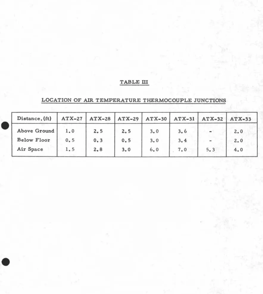
TABLE ill
LOCATION OF AIR TEMPERATURE THERMOCOUPLE JUNCTIONS
Distance.(it) ATX-Z7 ATX-Z8 ATX-Z9 ATX-30 ATX-31 ATX-3Z ATX-33
Above Ground 1.0 Z.5 Z.5 3.0 3.6
-
Z.OBelow Floor 0.5 0.3 0.5 3.0 3.4
-
Z.OLl"I ..,g
-19•
17 -18 19- 2A1 "'" 11 12 13-
-
•
_11 LEGEN 0 C"'\ 10 -12 @ Ground Temperature 10 -11 -12 In sta Ilation16
[!]
Main Switch Box .10 -11 12 -13 N セ Extension Cable lOA 2 IJ"...l4 15 -ATX-31t
0 9 .:. -12 REFERENCEMtJ. Eng. Co. Ltd. INC PC) Dwg. No. NCP-1l200 7
セ
•
-
•
10 11 7セ
I-7 8 10 11 12 13 14 15• •
• •
.:. 4--
-
•
10 11t2 t3
14-
-
-
-
-
-10 11 12 13 14 15 ATX-32---.g 9 -5 6 7 8-
7 8.
•
13 14 Ia..--...a 5 6 7 8 9 10 2 3 4 5 6 7 8 9•
n
-
•
n
:
:,
•
•
6 7 8 9 6セ
r.,
-
-3•
•
6 4 5-
-4 3 -5 --
•
6 7 8-
·4 3 -5 セ 0--7 P-..7•
3 R--7L-J
L-.I
2 3 4 2 3 4 5 6 7 10 5 0 10 20 30 FEET Iセ ,III!, , II I i I•
セJ
·
..
.
• • 1 • • •C
....:;a.II
•
t
B Q ....:;a. セ C'.I _I
2
F-;. 0010. G--?I· 1セセ
.... 11 1 J....:;a.kセヲセ
L -? Ll"I•
1 2 M--;:. "'" -2 N -? セ C"'\•
1 2 ATX- 2セ
2 3 4 5 6 7 8 910
V
t
2V
_..
•
A--7 • • • • • • • • FIGURE 1INUVI K POWER HOUSE PILE LAYOUT & THERMOCOUPLE CABLE LOCATIONS
Figure 2 Measuring Ground Temperatures at ATX.30, March 1958.
pipe Wire
spl i ce
Gro un d
MMNeセセAセセセセセセセセセセセWAAAAAAAAAAAAAAセ
Exte n sioncable cable
(a) TYPICAL SPLICE CONNECTION
I" ,
pipesleeve
ill
See detail in (a)
" , pipe Thermocouple cable pipe セセセセAAAAAAAAAAASッGセエッANNNZウ
wi
tc h :::: box Taped connection in (a) ATX-32(b) ATX-32 & 33 SPLICE CONNECTION
FIGURE 3