HAL Id: hal-01569252
https://hal.laas.fr/hal-01569252
Submitted on 1 Mar 2018
HAL is a multi-disciplinary open access
archive for the deposit and dissemination of
sci-entific research documents, whether they are
pub-lished or not. The documents may come from
teaching and research institutions in France or
abroad, or from public or private research centers.
L’archive ouverte pluridisciplinaire HAL, est
destinée au dépôt et à la diffusion de documents
scientifiques de niveau recherche, publiés ou non,
émanant des établissements d’enseignement et de
recherche français ou étrangers, des laboratoires
publics ou privés.
A mechanical descriptor of human locomotion and its
application to multi-contact walking in humanoids
François Bailly, Justin Carpentier, Bertrand Pinet, Philippe Souères, Bruno
Watier
To cite this version:
François Bailly, Justin Carpentier, Bertrand Pinet, Philippe Souères, Bruno Watier. A mechanical
descriptor of human locomotion and its application to multi-contact walking in humanoids. 7th IEEE
International Conference on Biomedical Robotics and Biomechatronics (BioRob) 2018, Aug 2018,
ENSCHEDE, Netherlands. �hal-01569252�
A mechanical descriptor of human locomotion and its application
to multi-contact walking in humanoids
F. Bailly
1,2,†, J. Carpentier
1,2, B. Pinet
1, P. Sou`eres
1, B. Watier
1,2Abstract— This work aims at experimentally identifying a new mechanical descriptor of human locomotion and demonstrating that it can be exploited for the generation of multi-contact motions for humanoids. For this purpose, an experimental setup was built on which five different experiments were carried out by 15 human volunteers. Experimental results show that the distance between the center of mass and the so-called central axis of the external contact wrench significantly varies as a function of locomotion phases and environmental constraints. This finding is combined with a theoretical reasoning in mechanics in order to exhibit how this distance is linked to the whole body’s angular acceleration and thus constitutes an interesting parameter to control. Finally, we illustrate the interest of this result for humanoid robot motion generation by embedding the minimization of the distance between the center of mass and the central axis of the external contact wrench in an optimal control formulation in order to generate multi-contact locomotion in simulation.
I. INTRODUCTION A. Motivations
Humanoid robotics and biomechanics share a common interest in the study of principles involved in human locomotion. Researchers from both fields have widely used the Zero Moment Point (ZMP) to describe and evaluate several properties of locomotion on horizontal walkways. This particular point is the intersection between the ground and the axis along which the moment of contact forces under the feet is collinear to the normal of the ground [1].
In biomechanics, this criterion has been used to investigate gait control analysis, running mechanics, prosthesis, shoes design and fall detection [2], [3]. In these approaches, researchers have usually studied the ZMP trajectory during several tasks, which is considered to reflect information about neuromuscular control [4]. In robotics, researchers have also controlled the ZMP to generate stable bipedal locomotion trajectories [5].
However, this criterion suffers from limitations as it is only defined when contacts are coplanar. Thus, it becomes irrelevant when motions involve multiple non-coplanar contacts while this situation is common in everyday life (stairs climbing, door opening, elderly locomotion ...) and increasingly used in humanoid robotics trajectory generation [6]. To overcome these limitations, several works have been done to expand the ZMP when locomotion is performed on uneven surfaces or when bipeds use multi-contact (cane, banister, etc.) [1], [7]–[9].
1LAAS-CNRS, 7 Avenue du Colonel Roche, F-31400 Toulouse, France 2University of Toulouse, UPS, LAAS, F-31400 Toulouse, France †Corresponding author([email protected])
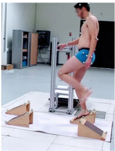
Fig. 1: Overview of the experimental setup during a recording session. A participant is asked to achieve a challenging locomotion task while using the handlebar to help himself.
B. Outline and contributions of the paper
In this paper, we propose to study human locomotion based on another mechanical approach related to the external contact wrench (ECW) (see Sec. II). The key idea is to consider the central axis ∆ of this wrench along which the moment of the contact forces applied to the body and the resultant of the contact forces are collinear. This axis is also the set of points where the overall moment induced by contact forces is minimal for the Euclidean norm (see Sec. II), and can always be computed even for generalized locomotion (uneven surfaces or multi contacts). According to Euler’s second law, the overall moment applied to the CoM equals the variation of angular momentum at the CoM, and thus reflects the whole body gesticulation [10]. This result establishes a link between the relative position of the CoM with regard to the central axis ∆ since, when they coincide, the variation of angular momentum at the CoM is minimal. Within the scope of bipedal locomotion, describing the relation between the need for angular momentum variations during certain phases and the quest for stability is a central question. In this context, the distance between the CoM and the central axis ∆, dG−∆, appears to be relevant for
describing the motion of the body in contact as it is related to the whole body dynamics in addition to be computed from the contact forces (see Sec. II).
After having theoretically demonstrated the consistency of our mechanical approach, the results of experimental tests in
humans are presented (see Sec. III). We hypothesized that the average dG−∆ should significantly vary as a function of
motion phases and of increasingly demanding environmental constraints. This conjecture was corroborated by setting up walking experiments to study five different locomotion tasks involving non-coplanar foot contacts and contacts with hands. In addition, results demonstrate that, at the scale of the walking cycle, dG−∆ conveys information about the
dynamical state of the body.
The interest of working with this mechanical quantity is finally illustrated in the context of multi-contact locomotion of humanoid robots (see Sec. IV). This is done by including dG−∆ in the cost function to be minimized within our
trajectory generation framework [6]. The simulation results performed with the model of the HRP-2 robot show that minimizing this distance under contact constraints leads to dynamically consistent and whole-body feasible centroidal trajectories. These results also support the fact that our criterion is less conservative than simply minimizing the variation of angular momentum, as commonly done in humanoid trajectory optimization [5].
II. MATHEMATICAL BACKGROUND
In the sequel, we denote by G the CoM of the body, by ∆ the central axis of the ECW and by dG−∆ the distance
between G and ∆. Contact forces can be represented by a single 3 dimensional vector f . At any point A, f induces a moment mA. f and mA define a moment field that can be
expressed at any point B as:
mB= mA+ f × pAB, (1)
where pAB gives the position of B with respect to A.
There exists one axis such that, at each point of this axis, the moment is parallel to f [11]. This axis, directed by f , is the so-called central axis of the ECW (∆). Without loss of generality, assuming that A ∈ ∆, and taking the Euclidean norm of (1) yields:
||mB||22= ||mA||22+ ||f × pAB||22+ 2 mA· (f × pAB), (2)
with 2 mA · (f × pAB) = 0 (hypothetically the moment
about A is parallel to f ). This leads to the conclusion that, at any point B, ||mB||22 ≥ ||mA||22, reaching the equality
when B belongs to ∆, along which the moment of contact forces is minimal. ∆ is computed as in [12]:
∀B in space, ∀A ∈ ∆, pBA=
f × mB
||f ||2 + λf , λ ∈ R. (3)
When λ = 0, A is the projection of B onto ∆. In particular, dG−∆ is: dG−∆ = ||f × mG|| ||f ||2 = || ˙hG|| · | sin(θ)| ||f || , (4) where ˙hG= mGis the derivative of the angular momentum
expressed at G and θ is the angle between f and ˙hG.
Hence, controlling this distance amounts to control either the derivative of angular momentum at G, or the angle between contact forces and the derivative of the angular momentum at
Force platform Wooden block
1
2
3
4
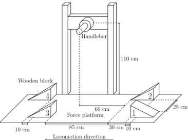
Handlebar 30 cm 10 cm 85 cm 10 cm 25 cm 60 cm 110 cm Locomotion directionFig. 2: Scheme of the experimental setup with the range of distances considered. The scenario is composed of four tilted and adjustable wooden blocks. Each wooden block is topped with an adherent layer to prevent subjects from slipping.
G, or the norm of contact forces. Furthermore, this distance contains information related to the centroidal dynamics of the body (see Sec. IV), which is ordinarily used in the control of humanoid robots. These observations will be discussed later on in Sec III and Sec. IV.
III. EXPERIMENTAL IDENTIFICATION OFdG−∆
The following section contains a description of the experimental protocol used to measure dG−∆ under
increasingly challenging locomotion tasks for humans and a presentation of the outcomes of this experiment.
A. Participants
Fifteen healthy male subjects (25.6 ± 5.8 y, height 1.77 ± .035 m, body mass 73 ± 8 kg) volunteered for this experiment. The participants had no prior or existing injury or neurological disorder affecting gait. Each participant was informed of the experimental procedure and signed an informed consent form prior to the study. The experiment was conducted in accordance with the declaration of Helsinki (rev. 2013) with formal approval of the ethics evaluation committee (IRB00003888, Opinion number 13-124) of the Institut National de la Sant´e Et de la Recherche M´edicale, INSERM, Paris, France.
B. Experimental protocol
Each participant had to execute five barefoot walking tasks under different stepping conditions, involving an additional hand contact or not (see Fig. 1). They performed three trials for each experimental condition. For each trial, two preliminary steps were achieved before crossing the force platform. Time intervals of about 3 minutes were adjusted to prevent fatigue between repetitions. For conditions involving non-coplanar contacts to be achieved, a custom made setup was built which consisted of four 35◦-sloped wooden blocks (i.e. three steps) fixed on the force platform embedded into
Task Standard walking Walking on setup Walking on setup using handlebar Speed Spontaneous Spontaneous Fast Spontaneous Fast
Condition A B D C E
dG−∆(mm) 55.1 ± 6.2 (74.8 ± 14.2)? 150.9 ± 34.4 69.6 ± 13.5 123.8 ± 25.1
Average speed (m.s−1) 1.0 ± 0.15 (0.71 ± 0.24)? (1.4 ± 0.35)† 0.73 ± 0.21 1.5 ± 0.32
TABLE I: Distances between the central axis of the external contact wrench and G, and average locomotion speeds across conditions A, B, C, D and E. Data are expressed as mean ± SD. Superscript ? (resp. †) stands for “Not significantly different from conditions C (resp. E)”.
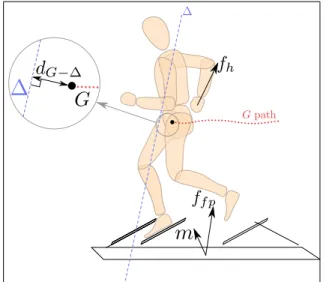
Fig. 3: Illustration of the different measurement involved in the experiment. ffp is the force recorded from the force
platform, fh is the force recorded from the handlebar, m
is the global moment expressed at the center of the force platform. ∆ is the central axis of the external contact wrench. The dashed curved line is the path of G in time. dG−∆ is
highlighted in the magnified portion of the image.
the floor. A 6-cells force sensor, hereafter called handlebar, was placed at 1.1 m high between blocks 2 and 3 (see details in Fig. 2). In the first condition (condition A), the volunteers were asked to achieve normal walking through the horizontal force platform, at spontaneous speed without any obstacle. After warming-up and getting familiarized with the experimental setup, participants were asked to walk on it (left foot first) for the four remaining conditions:
• B, at spontaneous speed, without handlebar
• C, at spontaneous speed, using the handlebar
• D, as fast as possible, without handlebar • E, as fast as possible, using the handlebar
For conditions B, C, D and E, subjects were asked to cross the platform walking on the wooden blocks only, which were intentionaly spaced in order to disturb locomotion (Tab. I). Therefore, walking on the experimental setup was the first challenging parameter used to complicate the locomotion task.
In [13] and [14], it has been shown that holding a fixed element during locomotion or, stair ascent and descent,
slightly improves stability and balance confidence. Thus, the prohibition of the additional hand contact was the second parameter. The third parameter was speed locomotion: the experimental setup was designed in such a way that it was hard to cross it fast. The volunteers were asked to perform the tasks in a given order of what we refer to as increasing complexity (i.e. conditions A, C, B, E then D).
C. Data acquisition
The computation of dG−∆ required to record the
ECW and the CoM position (see Eq. (4)). For the 3-dimensional kinematic analysis, 47 reflective markers were fixed on the subject’s bone landmarks for local frame reconstruction according to [15]. Body segments masses and center of mass positions were calculated in accordance with anthropometric tables [16]. Data were recorded by thirteen optoelectronic cameras sampled at 200 Hz. The 6-dimensional ECW applied to the subject was recorded by the force platform (180 × 90 cm) and the handlebar, both sampled at 2 kHz. The handlebar was localized thanks to 3D reflective markers. Data were synchronized using Nexus 1.7.1 and filtered using a 4th order, zero phase-shift, low-pass Butterworth with a 15 Hz cutoff frequency. The acquisition procedure started when the right foot of the subject left the floor and stopped before the left foot reached the floor, in order to record full contact motions (see Fig. 3).
D. Statistics
The average dG−∆ was computed for each subject and for
the five experimental conditions. Before statistical tests, data normality was assessed using the Kolmogorov-Smirnov’s test. Two separate one-way repeated measure ANOVAs were performed to compare the mean distance and the locomotion speed across conditions (p < 0.001) each followed by ten paired t-tests with the Bonferroni correction (p < 0.05/10) to assess the effect of each condition on dG−∆ and to verify if
speed instructions significantly modified subjects locomotion speed. The main hypothesis was accepted if the mean of dG−∆ significantly increased together with the complexity
of the locomotion tasks: conditions A, C, B, E then D. E. Experimental results
Fig. 4A shows dG−∆ (in average ± standard deviation)
for the three trials of each subject, in condition A. Fig. 4B shows the height of one of the right and left toes markers for one participant, in condition A. One normalized walking
Fig. 4: Normalized walking cycle in condition A (walking on flat ground). A: dG−∆ in mm as mean ± std, for the 15
participants. B: Height (z component) of the right and left toe markers for one participant.
cycle is displayed for both plots. Toe height profiles are used to identify the different phases of the walking cycle (single support, double support) and segment the time evolution of the distance displayed above (Fig. 4A). During double support phases, dG−∆ decreases, while it increases
during right and left swing phases (from 30 mm up to more than 100 mm). Values of the average CoM velocity and dG−∆ are displayed in Tab. I. The statistical analysis
revealed that locomotion speed in conditions B and C was significantly slower than in conditions A, D and E (about twice), and it was significantly faster in conditions D and E than in condition A. These results show that the participants followed the speed instructions correctly. Paired t-tests revealed that dG−∆in B tested against C could not be
said to be significantly different (Tab. I). The remaining data in Tab. I show that the mean distance significantly increased across the different conditions (ranging from 55.1 mm to 150.9 mm, by order of increasing distance : A,C-B,E then D).
F. Discussion
Because its depends on the whole body dynamics, the variation profile of dG−∆ at the scale of the walking cycle
is representative of the rhythm of locomotion as it allows to retrieve double support and leg swing phases. In addition to this temporal analysis, the average analysis of dG−∆
reveals that, compared to standard locomotion on level ground, asking the subject to walk on the experimental setup noticeably increased dG−∆(condition A against B, C, D and
E). Although one cannot conclude whether, at spontaneous speed, using the handlebar modified the distance dG−∆ or
not, in this study, at high speed, when subjects were allowed to stabilize themselves using the handlebar (condition E), the distance significantly decreased in comparison with the corresponding condition at the same speed but without the handlebar (condition D). When participants were asked to cross the platform at high speed (conditions D and E), dG−∆
increased in comparison with the corresponding conditions at spontaneous speed (conditions B and C). In essence, looking into the three different parameters used to perturb
the locomotion of the volunteers, dG−∆ increased with the
complexity of the task. dG−∆ being directly related to ˙hG,
this general result suggests that increasingly challenging locomotion tasks might require either more variation of angular momentum or non-collinearity between ˙hG and f .
The first possibility makes sense from a mechanical point of view, as both increased velocity and gesticulations due to uneven terrain lead to heavier inertial effects and thus to a larger ˙hG. For the second possibility to be filled, given that
contact forces are mainly vertical in the context of bipedal locomotion, the components of ˙hG must be horizontal and
correspond to tipping motions. This might be caused in particular by the inclination of the wooden blocks with regard to the gravity direction, and the whole-body resulting motions.
Finally, by revealing the instantaneous dynamic state of the body (double support, legs swings) or its average rotational behavior (gesticulation, tipping motions), dG−∆
characterizes the motion. G. Conclusion
In this first part, a mechanical quantity for characterizing human motion was introduced. Both theoretically and experimentally, it was shown to carry relevant information about the dynamics of the body in contact. In particular, it was demonstrated that the average value of dG−∆ over a
trajectory or its pattern during a walking cycle depends on the complexity and the phase of the locomotion task.
In biomechanics, this result is of particular interest, because, at the cost of estimating the CoM position, it provides a way of characterizing any whole body motion in contact, even in situations where the classical ZMP would fail (non-coplanar, multi-contact). For instance, it could be used for comparing standard and instrumented walking (e.g., elderly, prosthesis, exoskeleton) on uneven terrains. In addition, our proposal is quite different from the study of angular moment alone [17], [18], since dG−∆ includes the
coupling of the whole-body dynamics with contact forces. Therefore, the control of this quantity opens a larger space of strategies than those related to the control of the angular moment alone (see Eq. (4)). Finally, the dependence of dG−∆
on ˙hG and f supports that this value is plausibly controlled
by the central nervous system [19], [20].
In humanoid robotics, the control of the angular momentum has been the topic of a number of recent research activities, such as gait control [21] or balance assessments [22]. Although some work has been done to handle it for generating whole body motion in simulation, when it comes to real motion, humanoid robotics approaches are mostly conservative (e.g., angular momentum forced to zero by the model [5], or minimized inside a cost function). Although the dynamic nature of human locomotion results in varying profiles of dG−∆, one can choose to minimize this
quantity in order to implement a conservative whole-body behavior for the robot. This is illustrated in the next section, in which we propose to regulate dG−∆ as a cost for a stair
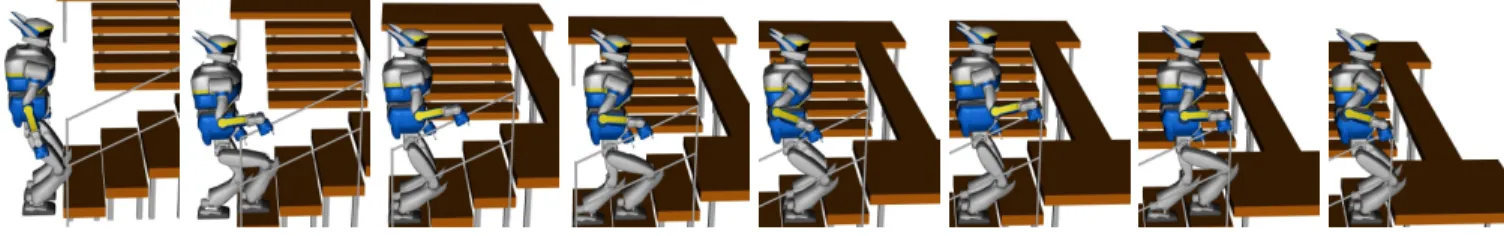
Fig. 5: Snapshots of the 15-cm steps climbing motion with handrail by the HRP-2 robot in simulation.
IV. HUMANOID ROBOT TRAJECTORY GENERATION In this section, we illustrate the minimization of dG−∆ in
the context of multi-contact locomotion for the humanoid robot HRP-2. In order to highlight its relevance for real applications, we apply this control strategy on a stair climbing scenario where the robot has to use the handrail for helping itself. After having shown the results of this simulation, we discuss why using dG−∆ differs from using
the angular momentum alone, and how it could be applied to other scenarios.
A. General overview of the motion generation pipeline The pipeline used is the same as the one originally introduced in [6] and extended in [23]. This formulation allows to compute a feasible trajectory (both kinematically and dynamically feasible) for the centroidal dynamics according to a sequence of contacts given as input. As a reminder, the centroidal dynamics is the dynamics of the whole-body system expressed at its CoM [24], involving CoM position together with linear and angular momenta. From the sequence of contacts and the centroidal dynamics trajectory, we use an inverse dynamics solver [25] to compute the whole-body motion. All the trajectories of the end-effectors were designed by hand.
B. Centroidal optimal control formulation
The central piece of this pipeline is the module for generating centroidal trajectories. To be effective, these centroidal trajectories must be dynamically consistent, i.e., all the contact forces which drive the centroid must lie inside the friction cones. In addition, these trajectories must be kinematically feasible by the whole-body model. For instance, the CoM trajectory computed by the module must be achievable by the whole body when computing its inverse dynamics.
To solve this problem, we set up a multi-stage optimal control problem (OCP) over a sequence of contacts S of the following form: min x,u,(∆ts) S
X
s=1 Z ts+∆ts ts `s(x, u) − log µs(x, u) | {z } feasibility measure dt (5a) s.t. ∀t x = f (x, u)˙ (5b) ∀t u ∈ K (5c) x(0) = x0 (5d) x(T ) = (cf, 0, 0), ˙x(T ) = 0 (5e)where (5a) is the cost function we aim to minimize that contains a feasibility measure to encode the constraints of the centroidal dynamics w.r.t. the whole-body [23], [26]. It also handles a tailored cost function `sthat can be adjusted
by the user to obtain smoother motions for instance, or to penalize some quantities. Eq. (5b) is the centroidal dynamics of the system with state x = (c, m ˙c, hG) composed of c,
the position vector of G, the linear momentum m ˙c, and the angular momentum hG. The control u is directly the
ECW. To be effective, this ECW must remain inside a certain cone called the centroidal wrench cone expressed in (5c) and introduced in [8]. In [26], the authors suggested an efficient inner approximation of this cone that we used in this work. Finally, starting from an initial state (5d), the objective is to reach a final state at rest, encoded by Eq. (5e). In this implementation, the duration of each phase (∆ts) was left as
a free variable of the problem. To solve this optimal control problem, we used MUSCOD-II [27], a multiple-shooting framework dedicated to problems having a shape similar to (5). In order to show the effects of our criterion, we provided the OCP solver with different cost functions `s:
1) In the first case, we investigated the minimization of the distance dG−∆ in addition to minimizing the
kinetic energy of the system in translation. Thus, we chose `s= dG−∆+ α mk ˙ck2, where α is a weighting
coefficient. Typically, α = 0.1.
2) In the second case, we left the distance free and the cost function was only composed of the kinetic term, leading to `s= mk ˙ck2.
C. Simulation results
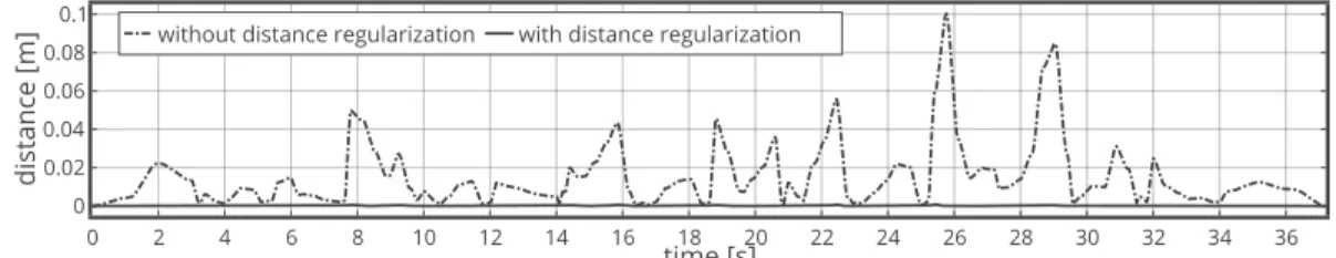
The simulated environment was an industrial stairway equipped with a handrail and made of four 15-cm high and 30-cm deep steps. Snapshots of the complete motion, result of the simulation, are depicted in Fig. 5. In Fig. 6 dG−∆ is
displayed for the two cases of study. When dG−∆is included
in the cost function, it is successfully regulated to nearly zero during the whole motion. Fig. 7 shows control inputs that drives the centroidal dynamics in the two approaches. As a result of the solved OCP, when our criterion is added to the cost function, the derivative of angular momentum about x and y axes is nearly zero. Reaction forces being mostly vertical in this kind of motion, the fact that the z component of the angular momentum variation is not zero is consistent with Eq. (4) and with the fact that dG−∆ is regulated to
almost zero. Furthermore, one can notice that minimizing the proposed criterion led to greater accelerations of the CoM.
Fig. 6: Traces representing the distance dG−∆ in the two cases of study: with and without regularization of dG−∆.
Fig. 7: Traces representing the control input (acceleration of the CoM and the angular momentum variations expressed at the CoM) that drives the centroidal dynamics in the two cases of study: with and without regularization of dG−∆.
Fig. 8: Traces representing trajectories of the state of the centroidal dynamics in the two cases of study: with and without regularization of dG−∆.
This might be the result of a tighter control of the position of the CoM for regulating dG−∆ to zero, together with a lesser
emphasis placed on the minimization of the kinetic energy (α parameter). Fig. 8, displays the state of the centroidal dynamics for the two cases of study. Noticeably, including our criterion in the cost function results in a nearly zero angular momentum about x and y axes which is an expected outcome of the computed optimal control.
D. Discussion
As mentioned earlier, minimizing dG−∆ leads to the
minimization of either ˙hG or the angle between fc and
˙hG or to the maximization of ||fc|| (see Eq. (4)). This last
strategy cannot be found by the solver since we also penalize the kinetic energy of the system in translation, which is
equivalent to bound the variations of the linear acceleration of the centroidal dynamics [28]. Simulation results show that in the context of stair climbing, the solution found by the optimal control framework is noticeably the same as if the criterion was to minimize ˙hG. But given the different
available strategies to control dG−∆, we claim that our
criterion allows for more slackness in the resolution of the problem. Typically, it should succeed in the context of a movement that would require dynamical direction changes and thus, non zero components of ˙hG along the direction
of f , a situation where harshly forcing ˙hG to zero would
fail. Also, one could extend the use of this criterion in a cost function, in order to make it follow a human-inspired pattern, as the one depicted in Fig. 4. In this case, the solver would be able to find a whole-body strategy that involves
contributions of all the limbs in the production of appropriate contact forces and angular momentum values, leading to a more dynamical, human-like locomotion. Implementing other motions using this criterion on the real robot is left as a future work.
V. CONCLUSION
In this work, we combined biomechanical experiments and robotics simulations in order to introduce a new mechanical descriptor of human locomotion, the distance between the CoM and the central axis of the ECW (dG−∆), and illustrated
its application to the generation of humanoid motion. At first, significant variations in this distance have been measured during experiments on 15 volunteers. At the scale of the walking cycle, this quantity was shown to convey relevant information about the instantaneous dynamical state of the body. It was also statistically demonstrated that the average of dG−∆ increased with the complexity of the
locomotion tasks, revealing information about the ongoing movement. In a second step, a conservative mechanical criterion was derived from this biomechanical study and implemented in an optimal control formulation in order to generate multi-contact motion for a humanoid robots and to observe its influence on numerical experiments. The results showed that the minimization of the distance dg−∆ led
to a dynamically feasible motion for the robot, resulting from a whole body dynamics expected from the mechanical analysis.
ACKNOWLEDGMENT
We thank the volunteers who took part in the experiment. We warmly thank Dr. Robin Baur`es, associate professor at the University of Toulouse for helping us with the statistics. This work is supported by the European Research Council through the Actanthrope project (ERC Grant Agreement 340050), the RoboCom++ FLAG-ERA JTC 2016 proposal and the French National Research Agency project Loco3D (ANR Grand Agreement ANR-16-CE33-0003).
REFERENCES
[1] P. Sardain and G. Bessonnet, “Forces acting on a biped robot. center of pressure-zero moment point,” Trans. Sys. Man Cyber. Part A, 2004. [2] G. R. Fernie, C. I. Gryfe, P. J. Holliday, and A. Llewellyn, “The relationship of postural sway in standing to the incindence of falls in geriatric subjects,” Age and Ageing, 1982.
[3] J. J. Collins and C. J. De Luca, “Open-loop and closed-loop control of posture: a random-walk analysis of center-of-pressure trajectories,” Experimental brain research, 1993.
[4] T. E. Prieto, J. B. Myklebust, R. G. Hoffmann, E. G. Lovett, and B. M. Myklebust, “Measures of postural steadiness: differences between healthy young and elderly adults,” IEEE Transactions on biomedical engineering, 1996.
[5] S. Kajita, H. Hirukawa, K. Harada, and K. Yokoi, Introduction to Humanoid Robotics, ser. Springer Tracts in Advanced Robotics. Springer Berlin Heidelberg, 2014.
[6] J. Carpentier, S. Tonneau, M. Naveau, O. Stasse, and N. Mansard, “A versatile and efficient pattern generator for generalized legged locomotion,” in IEEE-RAS Int. Conf. on Robotics and Automation (ICRA), 2016.
[7] K. Harada, S. Kajita, K. Kaneko, and H. Hirukawa, “Zmp analysis for arm/leg coordination,” in IEEE/RSJ Int. Conf. on Intelligent Robots and Systems (IROS), Oct 2003.
[8] H. Hirukawa, H. Shizuko, K. Harada, S. Kajita, K. Kaneko, F. Kanehiro, K. Fujiwara, and M. Morisawa, “A universal stability criterion of the foot contact of legged robots - adios zmp,” in IEEE-RAS Int. Conf. on Robotics and Automation (ICRA), 2006. [9] S. Caron, Q.-C. Pham, and Y. Nakamura, “Zmp support areas for
multicontact mobility under frictional constraints,” IEEE Transactions on Robotics, vol. 33, no. 1, pp. 67–80, 2017.
[10] P.-B. Wieber, “Holonomy and nonholonomy in the dynamics of articulated motion,” in Fast motions in biomechanics and robotics. Springer, 2006, pp. 411–425.
[11] F. M. Dimentberg, “The screw calculus and its applications in mechanics,” DTIC Document, Tech. Rep., 1968.
[12] T. Shimba, “An estimation of center of gravity from force platform data,” Journal of biomechanics, 1984.
[13] E. V. Lamont and E. P. Zehr, “Earth-referenced handrail contact facilitates interlimb cutaneous reflexes during locomotion,” Journal of neurophysiology, 2007.
[14] S. M. Reid, A. C. Novak, B. Brouwer, and P. A. Costigan, “Relationship between stair ambulation with and without a handrail and centre of pressure velocities during stair ascent and descent,” Gait & posture, 2011.
[15] G. Wu, F. C. Van der Helm, H. D. Veeger, M. Makhsous, P. Van Roy, C. Anglin, J. Nagels, A. R. Karduna, K. McQuade, X. Wang, et al., “Isb recommendation on definitions of joint coordinate systems of various joints for the reporting of human joint motion—part ii: shoulder, elbow, wrist and hand,” Journal of biomechanics, no. 5, pp. 981–992, 2005.
[16] R. Dumas, L. Cheze, and J.-P. Verriest, “Adjustments to McConville et al. and Young et al. body segment inertial parameters,” Journal of biomechanics, 2007.
[17] H. Herr and M. Popovic, “Angular momentum in human walking,” Journal of experimental biology, 2008.
[18] M. Popovic, A. Hofmann, and H. Herr, “Angular momentum regulation during human walking: biomechanics and control,” in IEEE-RAS Int. Conf. on Robotics and Automation (ICRA), 2004.
[19] T. Robert, B. C. Bennett, S. D. Russell, C. A. Zirker, and M. F. Abel, “Angular momentum synergies during walking,” Experimental brain research, vol. 197, no. 2, pp. 185–197, 2009.
[20] J. T. Yen, A. G. Auyang, and Y.-H. Chang, “Joint-level kinetic redundancy is exploited to control limb-level forces during human hopping,” Experimental brain research, vol. 196, no. 3, pp. 439–451, 2009.
[21] S. Yun and A. Goswami, “Momentum-based reactive stepping controller on level and non-level ground for humanoid robot push recovery,” in IEEE/RSJ Int. Conf. on Intelligent Robots and Systems (IROS), 2011., 2011, pp. 3943–3950.
[22] A. Goswami and V. Kallem, “Rate of change of angular momentum and balance maintenance of biped robots,” in IEEE-RAS Int. Conf. on Robotics and Automation (ICRA), 2004., vol. 4, 2004, pp. 3785–3790. [23] J. Carpentier, R. Budhiraja, and N. Mansard, “Learning feasibility constraints for multi-contact locomotion of legged robots,” in Robotics: Science and System (RSS), 2017.
[24] D. E. Orin, A. Goswami, and S.-H. Lee, “Centroidal dynamics of a humanoid robot,” Autonomous Robots, vol. 35, no. 2-3, pp. 161–176, 2013.
[25] L. Saab, O. E. Ramos, F. Keith, N. Mansard, P. Soueres, and J.-Y. Fourquet, “Dynamic whole-body motion generation under rigid contacts and other unilateral constraints,” Transactions on Robotics (TRO), 2013.
[26] J. Carpentier and N. Mansard, “Multi-contact locomotion of legged robots,” Submitted to IEEE Transactions on Robotics (TRO), 2017. [27] D. Leineweber, I. Bauer, H. G. Bock, and J. P. Schl¨oder, “An
efficient multiple shooting based reduced sqp strategy for large-scale dynamic process optimization. part 1: theoretical aspects,” Computers & Chemical Engineering, 2003.
[28] P.-B. Wieber, “Viability and predictive control for safe locomotion,” in IEEE/RSJ Int. Conf. on Intelligent Robots and Systems (IROS), 2008.