-1-A COMPUTER-B-1-ASED OPTIMIZ-1-ATION METHOD FOR PLASTIC DESIGN OF BRACED MULTI-STORY STEEL FRAMES
BY
LEROY ZACHARY EMKIN B.C.E., Georgia Institute of
(1965)
M.S.C.E., Georgia Institute of (1966)
Technology Technology
Submitted in partial fulfillment of the requirements for the degree of
Doctor of Philosophy
at the
Massachusetts Institute of Technology QOctober, 1969)
Signature of Certified by Accepted by.
Author....V.
- .
..
-
.,, ....-....
... .. .-...
..
.. ...
Departm t of Civil Engineering, October 3, 1969 Thesis Supervisor
.... e l m ... t...
Chairman, Departmental Committee on Graduate Students
Archives
e ss. INST. rEc
FEB 24 1970
ABSTRACT
A COMPUTER-BASED OPTIMIZATION METHOD FOR
PLASTIC DESIGN OF BRACED MULTI-STORY STEEL FRAMES
by
LEROY ZACHARY EMKIN
Submitted to the Department of Civil Engineering on October 3, 1969 in
partial fulfillment of the requirements for the degree of Doctor of Philosophy.
A method is developed for plastic design of both braced and unbraced multi-story steel frames including a consideration of elastic stress and elastic deflection constraints. It is applicable to rectangular multi-story planar frames of steel
with coplanar loading.
The method consists of three parts which are the plastic analysis and design part, the elastic analysis and elastic stress design part, and the elastic stiffness design part. The plastic analysis and design part for factored loads
follows a story by story optimization procedure in order to determine the most favorable force distribution in the frame. The optimization procedure utilizes a gradient search technique
intended to minimize material cost. In addition, by means of an iterative procedure, the so-called P-A effect due to
gravity loads acting in the laterally displaced position of the structure is accounted for. All member proportioning is in accordance with the 1969 AISC Manual of Steel Construction. The elastic analysis and elastic stress design part for service loadings performs an 'exact' matrix stiffness analysis of the structure and redesigns members in order to satisfy
im-posed elastic stress constraints. Finally, the elastic stiffness design part for service loadings is executed in
order to satisfy imposed elastic lateral deflection con-straints. This part also utilizes a story by story gradient search optimization technique in order to minimize the
material cost increase needed to satisfy the elastic de-flection constraints.
-3-A computer design system, written in the Fortran IV language, is also developed to execute the proposed design method.
The practicality and efficiency of the design method is illustrated by several example problems. The results indicate that satisfactory and economical designs may be obtained by the proposed design method.
Thesis Supervisor: William A. Litle
ACKNOWLEDGEMENT
The work reported herein was sponsored by an American Iron and Steel Institute Engineering Fellowship. The author gratefully ac-knowledges this support. This work was done in part at the Informa-tion Processing Services Center at M, I. T., Cambridge, Massachusetts.
The author wishes to express his indebtedness to his thesis supervisor, Professor W. A. Litle, for his many valuable suggestions and advice.
The author acknowledges Barbara Emkin, Eunice Taylor, Carol Hewson, Candy Richardson, and Pat Dean for their fine typing of this thesis.
To the author's wife, Barbara, who not only assisted in the
typing of this thesis as well as perform the duties of wife and mother, but whose patience and encouragement have contribed much to
the successful completion of the author's graduate study at the Massachusetts Institute of Technology, this work is dedicated.
-5-TABLE OF CONTENTS Page TITLE PAGE 1 ABSTRACT 2 ACKNOWLEDGEMENT 4 TABLE OF CONTENTS 5 LIST OF FIGURES 10 LIST OF TABLES 15 DEFINITIONS OF SYMBOLS 16 CHAPTER 1 INTRODUCTION 26
1.1 Objective of this Dissertation 26
1.2 Description of the Design Methodology 27
1.2.1 Input of the Design 28
1.2.2 Plastic Design 38
1.2.3 Elastic Stress Design 42
1.2.4 Elastic Stiffness Design 43
1.2.5 Output of the Design Results 45
1.3 General Design Conditions and Limitations 45
1.4 Computer Requirements 47
CHAPTER 2 SUMMARY OF RESULTS 48
2.1 Frame B General Design Data 49
2.2 Frame C General Design Data 51
2.3 List of Example Problems with Additional
Design Data 53
2.4.1 Comparisons Between the Author's and Lehigh University's Design Solutions 2.4.2 Effects of Depth Constraints
2.4.3 Comparison of the Free Bracing Case wi.th Several Selected Bracing Patterns 2.5 A Detailed Consideration of Selected Results
2.5.1 Examples of the Approximate Deflection Analysis
2.5.2 Effects of the Elastic Stress Design 2.5.3 Effects of the Elastic Stiffness Design 2.5.4 A Difficulty in the Elastic Stiffness
Design Method
CHAPTER 3 PLASTIC ANALYSIS AND DESIGN METHOD 3.1 Introduction
3.2 Summary of Proposed Method 3.3 Notation and Sign Convention 3.4 Basic Equilibrium Relations 3.5 Joint Size Effect
3.6 Force Distribution Under Factored Gravity Load 3.7 Story Shear Distribution with Sensitivity
Coefficients
3.7.1 Formulation of the Sensitivity Coefficients 3.7.1.1 Sub-Sensitivity Coefficient of
Columns Below Panel
j
3.7.1.2 Sub-Sensitivity Coefficient of Beams Adjacent to Panel j
Page 121 121 123 126 126 135 136 140 143 149 153
-7-Page 3.7.1.3 Sub-Sensitivity Coefficient of
Panel j Members
3.7.1.4 Change in Required Member Area with Respect to Changes in Required Force Capacities
3.7.2 Calculation of Applied Incremental Story Shear,
3.8 Member 3.7.2.1 AH Due to Panel
j
3.7.2.2 AH Due to Panel j 3.7.2.3 AH3 Due to 3.7.2.4 AH Due to 3.7.2.5 AH Due to 3.7.2.6 AH Due to 3,7.2.7 AH Due to 3.7.2.8 AH Due to Selection AH3 Story i Beams to Left ofStory i Beams to Right of Upper Beam in Panel j Lower Beam in Panel j Columns Below Panel j Columns in Panel j
Tension Brace in Panel j
Moment State Changes in Panel
j
3.9 Empirical Relations between Section Properties 3.10 Calculation of A for the P-A Effect
3.10.1 Braced Panel
3.10.2 Unbraced Panel
3.11 Beam and Column Depth Constraints
CHAPTER 4 ELASTIC ANALYSIS AND ELASTIC STRESS DESIGN METHOD 4.1 Introduction
4.2 Notation and Sign Convention
156 190 196 198 199 200 201 202 203 204 204 207 212 217 219 219 220 223 223 224
Page
4.3 Member Global Stiffness Matrices 226
4.3.1 Beams 226
4.3.2 Columns 230
4.3.3 Tension Bracing for Wind from Right (Brace Type 1) 235 4.3.4 Tension Bracing for Wind from Left (Brace Type 2) 238
4.4 StructureStiffness Matrix 241
4.5 Square Root Method 250
4.6 Force Vector 253
4.7 Elastic Member Design 254
CHAPTER 5 ELASTIC STIFFNESS DESIGN METHOD 258
5.1 Introduction 258
5.2 Summary of the Elastic Stiffness Design Method 259 5.3 Relative Story Deflection Due to Beam and Column
Bending and Tension Brace Elongation 262
5.3.1 Unbraced Plane Frame 262
5.3.2 Diagonally Braced Plane Frame 269
5.4 Relative Story Deflection Due to Column Elongation
and Shortening 278
5.5 Method of Optimization for Elastic Deflection Constraints 283 5.5.1 Beams, Columns, and Tension Brace in Story i 285
5.5.2 Columns Below Story i 286
CHAPTER 6 RECOMMENDATIONS 287
-9-Page APPENDICES
A. SECTION PROPERTIES OF ROLLED STEEL SHAPES USED IN THE ILLUSTRATIVE EXAMPLES
B. FRAME B LOADING DATA C. FRAME C LOADING DATA
D. DESCRIPTION OF COMPUTER PROGRAM INPUT FORMAT BIOGRAPHY 291 307 311 314 325
LIST OF FIGURES
Figure Page
1.1 Macro Flow Chart of Total Design System 29
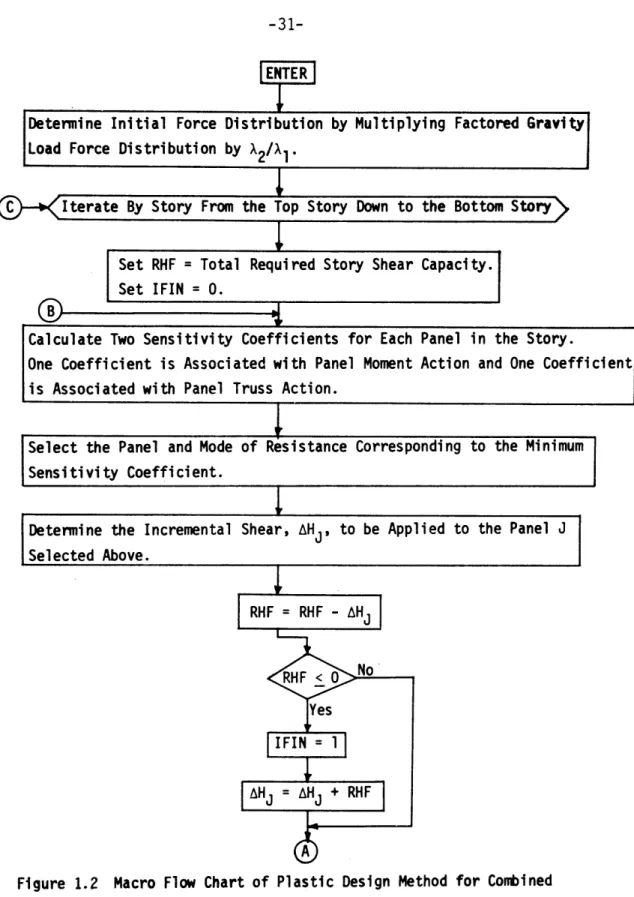
1.2 Macro Flow Chart of Plastic Design Method for
Combined Load Condition 31
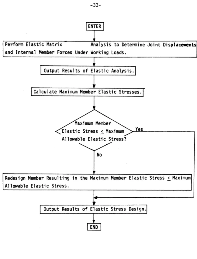
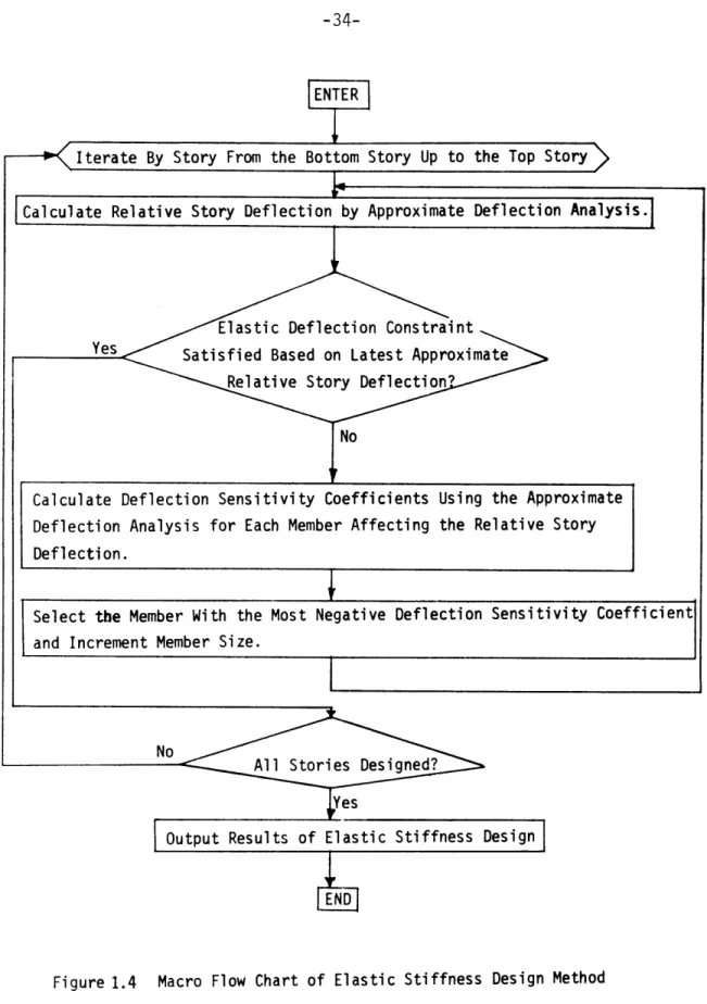
1.3 Macro Flow Chart of Elastic Stress Design Method 33 1.4 Macro Flow Chart of Elastic Stiffness Design Method 34
1.5 Geometrical and Loading Conditions 35
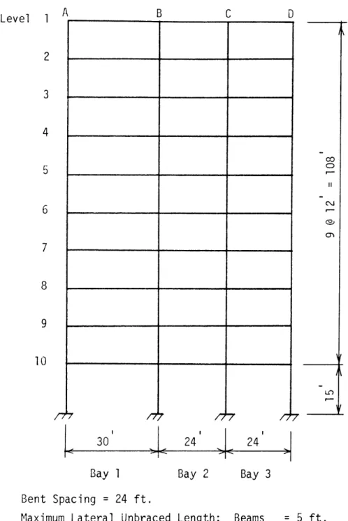
2.1 Frame B Geometry 50
2.2 Frame C Geometry 52
2.3 Example Problem B1.1A 82
2.4 Example Problem B1.1L 83
2.5 Example Problem B2.1A 84
2.6 Example Problem B2.1L 85
2.7 Example Problem B3.1A 86
2.8 Example Problem C1.1A 87
2.9 Example Problem C1.1L 88
2.10 Example Problem C1,2A 89
2.11 Example Problem C2.1A 90
2.12 Example Problem C2.2A 91
2.13 Example Problem C3.1A 92
2.14 Example Problem C3.2A 93
2.15 Example Problem C4.1A 94
V
-11-Figure 2.17 2.18 2.19 2.20 2.21 2.22 2.23 2.24 2.25 2.26 2.27 2.28 2.29 2.30 Example Example Example Example Example Example Example Example Example Example Example Example Example Example Probl em Problem Probl em Problem Problem Problem Problem Problem Problem Probl em Problem Probl em Problem Problem C5.1A C5.2A C6. 1A C6.2A C7.1A C7. 1L C7.2A C8. 1A C8.2A C9. 1A C9.1L C9.2A C10.1A C10.2A2.31 Example C1.2A, Initial and Final Elastic Relative
Story Deflections
2.32 Example C2.2A, Initial and Final Elastic Relative Story Deflections
2.33 Example C4.2A, Initial and Final Elastic Relative
Story Deflections
2.34 Example C10.2A, Initial and Final Elastic Relativ Story Deflections
2.35 Example C9.2A, Initial Elastic Relative Story Deflections
2.36 Example C9.2A, Elastic Relative Story Deflections
After First Execution of the Elastic Stiffness
Design Page 96 97 98 99 100 101 102 103 104 105 106 107 108 109 110 111 112 113 114 e 115
Figure Page
2.37 Example C9.2A, Elastic Relative Story
Deflections After Second Execution of the Elastic
Stiffness Design 116
2.38 Example C9.2A, Elastic Relative Story Deflections
After Third Execution of the Elastic Stiffness Design 117 2.39 Example C9.2A, Elastic Relative Story Deflections
After Fourth Execution of the Elastic Stiffness
Design 118
2.40 Example C9.2A, Elastic Relative Story Deflections
After Fifth Execution of the Elastic Stiffness Design 119 2.41 Example C9.2A, Elastic Relative Story Deflections
After Sixth and Final Execution of the Elastic
Stiffness Design 120
3.1 Positive Sign Convention for Moment, Axial Force
and Shear 127
3.2 Notation 128
3.3 Beam Moment Diagram 129
3.4 Column Moment Diagram 129
3.5 Beam Force Equilibrium 131
3.6 Beam Mechanism Failure 138
3.7 Typical Moment Distribution Due to Factored Gravity
Loads 141
3.8 Panel Model 144
3.9 Model for the Calculation of AH 146
3.10 Model for the Calculation of the Sub-Sensitivity
Coefficient of Columns Below Panel j 150 3.11 Model for the Calculation of the Sub-Sensitivity
Coefficient of Beams Adjacent to Panel j 154
3.12 Moment Diagram Under Factored Gravity Loads in the
-13-Figure Page
3.13 Initial Moment Diagram Under Factored Combination
Loads in the Moment State Model Panel 167
3.14 Initial Moment Diagram of Moment State 2 168
3.15 Initial Moment Diagram of Moment State 3 168
3.16 Initial Moment Diagram of Moment State 4 169
3.17 Free Body Diagram of Upper Half of Panel j 169 3.18 Free Body Diagram of Upper Left Joint of Panel j 173 3.19 Free Body Diagram of Right Half of Panel j 173
3.20 Free Body Diagram of Upper Right Joint of Panel
j
176 3.21 Free Body Diagram of Upper Half of Panel j 1763.22 Free Body Diagram of Panel j 179
3.23 Free Body Diagram of Tension Brace 179
3.24 Terminal Upper Beam Moments in Moment State 2 182 3.25 Empirical Relations Between Section Area (A) and
Plastic Section Modulus (Z) for the Economy Beams
and Columns Used in the Illustrative Examples 214
3.26 Empirical Relations Between Radius of Gyration
(r & ry) and Plastic Section Modulus (Z) for the Economy Beams and Columns Used in the Illustrative
Examples 215
4.1 Global Joint Displacements and Forces 225
4.2 Joint Numbering Convention 225
4.3 Beam Left Joint Unit Displacements and Resulting
End Forces 227
4.4 Beam Right Joint Displacements and Resulting
Figure Page 4.5 Column Bottom Joint Unit Displacements and
Resulting End Forces 232
4.6 Column Top Joint Unit Displacements and
Resulting End Forces 233
4.7 Tension Brace Type 1 Joint Unit Displacements
and Resulting End Forces 236
4.8 Tension Brace Type 2 Joint Unit Displacements
and Resulting End Forces 239
4.9 Two-Story, One-Bay Frame 244
4.10 Structure of the Structure Stiffness Matrix 249 4.11 Fixed-End Forces Due to Uniform Beam Loads 256
4.12 Maximum Beam Moment 256
5.1 Relative Story Deflections 263
5.2 Unbraced Story Level Equilibrium 270
5.3 Braced Story Level Equilibrium 270
5.4 Brace Deformation 273
-15-LIST OF TABLES
Table Page
2.1 Material Cost and Weight for Frame B, All
A36 Steel 76
2.2 Material Cost and Weight for Braced Frame C,
All A36 Steel 77
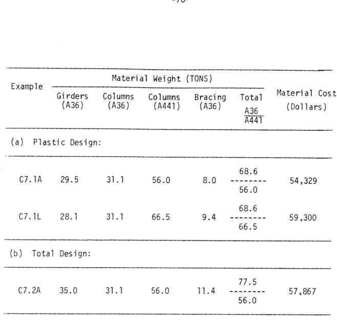
2.3 Material Cost and Weight for Braced Frame C,
A36 and A441 Steel 78
2.4 Material Cost and Weight for Unbraced Frame C,
A36 and A441 Steel 79
2.5 Material Cost and Weight for Unbraced Frame C,
All A36 Steel 79
2.6 Example C2.2A, Elastic Relative Story
Deflections Prior to First Execution of the Elastic Stress and Elastic Stiffness Design,
Wind from Left 80
2.7 Example C1.2A, Elastic Relative Story Deflections
Prior to First Execution of Elastic Stress and
Elastic Stiffness Design, Wind from Left 81
Al Economy Beam Sections 292
A2 Non-Economy Beam Sections 295
A3 Economy Column Sections 299
A4 Equal Leg Double Angle Bracing Sections 303
DEFINITIONS OF SYMBOLS AB(i
,j)
ABR(i,j)
ABR(i ,jk) AC(i,j) AK(pk) B(i,j)
C C(i,j) CAHJ Cv(j) db(i,j) d (i,j)
d c(ij) d'(i,j) A(i) A(i,j)= area of beam (i,j).
= area of panel (ij) tension brace.
= ABR(ij) for wind from left (k=2) or wind from right (k=l)
= area of column (i,j).
= one-level array representation of K.
= beam (i,j).
= plastic design flag indicating mode of panel resis-tance (0.0 = moment resistance, -1.0 = truss resis-tance).
= Column (i,j).
= horizontal component of tension brace force.
= ratio of P to Pi. = depth of beam (i,j).
= average beam depth in panel
= depth of column (iJ).
= average column depth in panel
(i,j).
(i,J).
= relative story i deflection.
= panel (i ,j) relative story deflection.
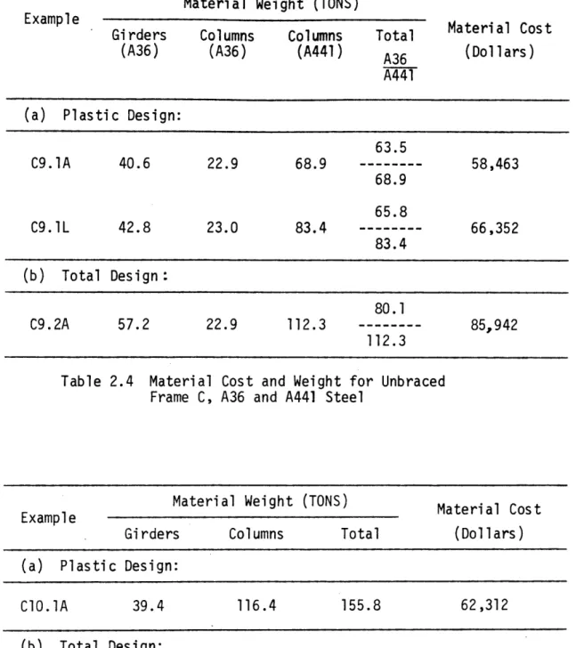
= total approximate elastic relative story deflec-tion.
-17-A b = elastic relative story deflection due to beam elongation and shortening effects.
Ao= c (i) calculated at the beginning of the elastic stiffness design.
A (i) = approximate elastic relative story i deflection due c to column elongation and shortening effects.
Ae = 'exact' relative story deflection.
A. = 'exact' relative story gravity sway deflection. g
As0 = s(i) calculated at the beginning of the elastic
stiffness design.
A (i) = approximate elastic relative story i deflection due to beam and column bending and tension bracing elongation.
T = approximate elastic relative story deflection com-puted at the end of each execution of the elastic stiffness design.
AH = total incremental shear applied to panel j.
= incremental shear applied to top left joint of
1 panel
j.
A H2 = incremental shear applied to top right joint of
panel
j.
AM = change in panel top beam right joint moment.
AM' = change in panel beam end moment (at face of col-umn).
AM1 = AM due to AH
1 .
(9F Beam
P Column ( -)TFColumn AM B AMBC AMBL AMBR AM aMT J CBP J BLP J BRP =sub-sensitivity coefficient of story i right of panel j.
beams to
= sub-sensitivity coefficient of a panel member.
= change in beam cost with respect to changes in beam plastic moment capacity.
= change in beam cost with respect to changes in beam axial force capacity.
= change in column cost with respect to changes in
column plastic moment capacity.
= change in column cost with respect to changes in column axial force capacity.
= change in panel beam end moment (at face of column).
= increment of mid-span beam moment.
= increment of left joint beam moment.
= increment of right joint beam moment.
= change in panel column end moment (at face of beam).
= total change in top right joint beam moment.
= sub-sensitivity coefficient of columns below panel
j.
= sub-sensitivity coefficient of story i beams to left of panel j.
(I )
3J panel
member
-19-= change in tension brace cost with respect to changes in brace axial force capacity.
= modulus of elasticity.
= total error in the A a calculation.
= error in the latest approximate deflection calcula-tion not including gravity sway effects.
FB(i,j)
FBL fBL FBR FBR( ,j) FBR(i ,j,k) fCB F c(ij)= required axial force capacity.
= cost of all members affecting relative story de-flection.
= beam (i,j) axial force.
= beam axial force to left of panel j. = cost of a single beam to left of panel j. = beam axial force to right of panel j. = panel (i,j) tension brace axial force.
= axial force in panel (i,j) tension brace for wind from the left (k=2) or wind from the right (k=l).
= column axial force below panel j.
= cost of a single column below panel j.
= column (i,j) axial force.
fT = cost of all member which experience force changes due to the application of AH3 to panel j.
(fbeams adjacent = cost of top beams adjacent to panel j.
to panel (3)Tension
(fcolumns below panel )panel beams (fMpanel columns (fMpanel tension brace H(i)
HT(i
h(i) IB(ij) Ic (i J) K K kBKB(i
,j)
B1 BR2 C K (i,j) Sc= cost of columns below panel
j.
= cost of beams in panelj.
= cost of columns in panelj.
= cost of tension brace in panel
j.
= lateral unfactored concentrated load applied at exterior joint of story level i from the left or right.
= sum of factored lateral loads from story 1
down to and including story i. = height of story i.
= moment of inertia of beam (i,i).
= moment of inertia of column (i,j). = ratio of AH
2 to AH1 .
= beam stiffness matrix.
= beam (i,j) stiffness (IB(ij)/L(j)).
= tension brace type 1 stiffness matrix.
= tension brace type 2 stiffness matrix. = column stiffness matrix.
= column (i,j) stiffness (Ic (ij)/h(i = structure stiffness matrix.
-21-kBij = element (i,j) of beam stiffness matrix.
k cij = element (i,j) of column stiffness matrix.
k sa = element (i,j) of beam stiffness matrix.
L(j) = length of bay j.
L'(j) = clear span length of beam j.
LB(i,j) = diagonal brace length in panel (i,j). = arbitrary load factor.
= load factor for the gravity load condition.
X2 = load factor for the combination gravity plus wind load condition.
M = number of stories.
M9j) = sum of column joint moments at joint
j
in storylevel under consideration. MBC('j) = beam (i,j) mid-span moment.
MBC(kj) = panel j mid-sp moment in top beam (k=l) or bottom beam (k=2).
MBL(i,j) = beam (ij) left joint moment.
MBL(ij) = beam (i,j) left end moment (at face of column).
MBL (kj) = panel j left joint moment in top beam (k=) or bottom beam (k=2).
MBP(i,j) = beam (i,j) required plastic moment capacity.
MBP(k9j) = panel
j
required plastic moment capacity for topbeam (k=) or bottom beam (k=2). MBR(i,j) = beam (i,j) right joint moment.
MBR(i,j) = beam (i,j) right end moment (at face of column).
MBR(k,j) = panel
j
right joint moment in top beam (k=) or bottom beam (k=2).MBR(kj) = panel
j
right end moment (at face of column) in top beam (k=1) or bottom beam (k=2).MBRmax = terminal value of upper right joint beam moment. MR,max = terminal value of upper right end beam moment (at
face of column).
M CB(i,j) = column (i,j) bottom joint moment.
MCB(i,j) = column (i,j) bottom end moment (at face of beam). MCB(i) = column
j
bottom joint moment.MCP(i,j) = column (i,j) required plastic moment capacity. MCT(i,j) = column (ij) top joint moment.
M T(ij) = column (i,j) top end moment (at face of beam). MCT(j) = column
j
top joint moment.M P= required plastic moment capacity.
N = number of stories.
NIC = number of columns in a story.
NJ = total number of joints in frame not including joints at the foundation.
P.(i,j) = apOlied concentrated unfactored gravity joint loads.
P = axial member force equal to the product of member area and steel yield stress.
-23-P W0ij) = in plastic design: equivalent concentrated load
applied at mid-span of beam (i,j).
PW(ij) = in elastic design: applied unfactored uniform grav-ity beam load.
Pi = equivalent concentrated load applied at mid-span of top beam in panel model.
P = equivalent concentrated load applied at mid-span of bottom beam in panel model,
$(i,j) = column (i,j) rigid body rotation.
p(i)
= average of story i rigid body column rotations,QB(i5j) = beam (i,j) deflection sensitivity coefficient. QBR(i,j) = panel (i,j) tension brace deflection sensitivity
coefficient.
Qc(i,j) = column (i,j) deflection sensitivity coefficient. R(i) = sum of horizontal components of tension brace force
in story i.
(i,j) = horizontal component of tension brace force in panel (i,j).
r = non-dimensional distance from bottom column joint
to column inflection point.
r x= radius of gyration about major axis. ry = radius of gyration about minor axis.
p = mass density of steel.
S(j) = in plastic design, lateral shear load applied to joint j in story level under consideration.
S(i) = in elastic stiffness design, sum of unfactored wind loads from top story level down to and
SE = elastic member stress.
ST(i) = equivalent required shear capacity of story i.
a x maximum elastic member stress.
aY = steel yield stress.
a B = beam steel yield stress.
GYBR = brace steel yield stress. aYC = column steel yield stress.
O = in plastic design, beam rotation at a plastic hinge.
0(i) = in elastic stiffness design, story level i joint rotations or story level i rigid body beam rota-tions.
0 L = left joint beam rotation.
8R = right joint beam rotation.
UB(i,j) = unit material cost of beam (i,j).
UBR(i,j) = unit material cost of panel (i,j) tension brace. Uc (i,j) = unit material cost of column (i,j).
Vc(i,j) = column (i,j) joint shear.
w(i,j) = uniformly applied unfactored gravity beam load. W(i,j) = uniformly applied unfactored gravity beam load.
W D = uniforily applied dead floor load.
-25-ZB = beam plastic section modulus.
CHAPTER 1 INTRODUCTION 1.1 Objective of this Dissertation.
As a result of many years of concentrated research both in this country and abroad plastic design of steel framed structures has become an accepted design method. For several years the American Institute of Steel Construction's Specification for the Design, Fabri-cation and Erection of Structural Steel for Buildings has permitted plastic design for simple one and two story frames as well as continuous beams. For such simple structures plastic design is easily amenable to hand computation and, in many respects, is more easily accomplished than the alternative elastic design. The February
1969 revision of the AISC Specification now permits plastic design of braced multistory frames and it seems likely that a subsequent revisionn will permit plastic design of unbraced multistory frames as well. Unlike the situation for continuous beams and one story frames the plastic
design procedures of multistory frames are not simple. In many ways they are more complex and demanding than the alternative elastic design procedures which have been in use for some years.
The objective of this dissertation was to develop a practical and efficient computer system for the plastic design of both braced and un-braced multistory steel frames. For unun-braced frames the system simply proportions individual beams and columns according to a certain optimi-zation procedure. For braced frames the system also examines the
-27-question of where braces should be located, given that there is some flexibility in this regard. The work is computer oriented not because plastic design of such structures by hand computation is not possible, but rather because the enormous amount of data which must be processed makes a computer solution the most rational approach.
This dissertation follows and builds upon an earlier doctoral dissrtaton f Y.Nakaura(6)
dissertation of Y. Nakamura( First of all, Nakamura's dissertation contains an excellent historical review of the research efforts related
to plastic design. The review will not be repeated or expanded here. More importantly, his work, while limited to unbraced frames, contains a basic organizational focus which appears sound and was followed.
1.2 Description of the Design Methodology
The computer system described herein consists of the following five parts:
1. Input of the design problem.
2. A strength design for factored ultimate loads.
3. An elastic analysis for working loads. Modification of
member sizes when elastic stress limits are exceeded. 4. An elastic stiffness design if, at working loads, lateral
story deflection limits are exceeded.
5. Output of design results.
Figure 1.1 shows a macro flow-chart of the overall computer system. In somewhat more detail, Figure 1.2 shows a macro flow-chart for the plastic design for factored combined load condition, Figure 1.3 shows a similar chart for the 'exact' elastic analyses and elastic stress
design, and Figure 1.4 shows a chart for the elastic stiffness design. 1.2.1 Input of the Design
The units of input are kips and inches unless specifically mentioned. Details of the form of the input are given in Appendix D.
1. Geometrical Conditions.
The proposed design method considers multistory plane frames with coplanar loads as illustrated in Fig. 1.5. The story levels of the frame are numbered from top to bottom. Geometrical data to be given are as follows.
M : Number of stories,(2 < M < 30).
N : Number of bays, (2 < N < 5).
L(j) : Span length of bay
j.
h(i) : Height of story i. 2. Loading Conditions.The working 'loads applied to the frame are also shown in Fig. 1.5. Loading conditions are as follows.
i. D.L. + L.L.
ii. D.L. + L.L. + W.L.
As input data, D.L. + L.L. are uniformly distributed vertical loads on beams and concentrated vertical loads on joints. W.L. are concentrated horizontal loads at the external joints of the frame. Ultimate loads applied to the frame are calculated by the comouter orograms by multiplying loading conditions i and ii by the appropriate load factors.
-29-ENTER
|Input Dataj
Calculate Factored Gravity Load Force Distribution. Determine Beam and Column Section Sizes on the Basis of
Beam Mechanism Failures for the Factored Gravity Load Condition. Perform Plastic Design for the Factored Combined Gravity
plus Lateral Load Condition.
Ultimate Deflection A.
Convergence Criterion Satisfied?
Yes
Compute New Lateral Load Distribution Based on New Story A's.
Perform 'Exact' Elastic Analyses for Unfactored Loading Conditions. Modify Members When Elastic Stress Limits are Exceeded.
Perform Elastic Stiffness Unfactored Load Lateral Design Utilizing Approxi-Story Deflection Constraints No mate Deflection Analysis
Satisfied Based on Latest (Stiffness Design for
'Exact' Relative Story Unfactored Combined Loads). Deflections?
Yes
A
Perform Final Plastic Design Check for Satisfaction of Plastic Design Code Formulae. Modify Members if Necessary.
Output Final Design]
-31-Determine Initial Force Distribution by Multiplying Load Force Distribution by X2/A1'
Factored Gravi ty
IC terate By Story From the Top Story Down to the Bottom Story
Set RHF = Total Required Story Shear Capacity.
Set IFIN =0. @
Calculate Two Sensitivity Coefficients for Each Panel in the Story.
One Coefficient is Associated with Panel Moment Action and One Coefficient is Associated with Panel Truss Action.
Select the Panel and Mode of Resistance Corresponding to the Minimum
Sensi ti vi ty Coefficient.
Determine the Incremental Shear, AHJ, to be Applied to the Panel J Selected Above.
RHF = RHF - AH
Figure 1.2 Macro Flow Chart of Plastic Design Method for Combined Load Condi tion
Apply AH3 to Panel J and Determine New Force Distribution.
Check and Redesign If Necessary All Members Experiencing Force Changes Due to the Application of AH .
B No IFIN = 1
Yes No
Yes
Output Resul ts of Pl as tic Design.
-33-ENTER
Perform Elastic Matrix Analysis to Determine Joint Displacements and Internal Member Forces Under Working Loads.
Output Results of Elastic Analysis.
Calculate Maximum Member Elastic Stresses.
Maximum Member
Elastic Stress < Maximum Yes Allowable Elastic Stress?
No
Redesign Member Resulting in the Maximum Member Elastic Stress < Maximum
Allowable Elastic Stress.
Figure 1.3 Macro Flow Chart of Elastic Stress Design Method
ENTER
Iterate By Story From the Bottom Story Up to the Top Story
Calculate Relative Story Deflection by Approximate Deflection Analysis.
Elastic Deflection Constraint Yes Satisfied Based on Latest Approximate
Relative Story Deflection? No
Calculate Deflection Sensitivity Coefficients Using the Approximate Deflection Analysis for Each Member Affecting the Relative Story Deflection.
Select the Member With the Most Negative Deflection Sensitivity Coefficient and Increment Member Size.
No
All Stories Designed? Yes
Output Results of Elastic Stiffness Design
V w(l,1)2 Level 1 H(l) 2 H(2) i H(i) M H(M) I I -35-P. (1,2) w(l ,2)-j I I I P.i(251)
P.i(292)
w(2,1)2 (,) wi,1 P (i,2) 1w(i 2)~ - -I -- --b , L(l) Bay 1 V I I I irr P(1,j)2
w(1,j)2 w(29)P
rP (i,j)w(i,j)
I1
L(2) Bay 2 L(j) Bay jGeometrical and Loading Conditions
I I (2,j+l) P (i,j+ -M
+
-F
Iw
II
(/"Y7
I
I
I i ia Fi gure 1. 5 P (1, j+1 )3. Material Properties.
Any grade of steel may be used. However, the grade of steel (i.e. A36, A441, etc.) must be input for each member in the frame in-cluding bracing elements even if bracing is not used.
Data to be given are
aYB : Yield stress of a beam. One value for each beam. aYC : Yield stress of a column. One value for each column. &YBR: Yield stress of a brace. One value for each set of
diagonal braces in each bay.
UB,UC9UBR: Unit material costs (cents/pound) corresponding to each of the above specified yield stresses.
4. Load Factors.
1 : Load factor under D.L. + L.L.
2 : Load factor under D.L. + L.L. + W.L.
5, Design Constraints.
i. Maximum permissible relative story deflections under working loads.
ii. Maximum permissible elastic member stresses under working loads.
iii. Maximum permissible beam and column depths.
iv. Actual maximum unsupported beam and column lengths with resnect to out-of-plane deformation.
v. Panel codes indicating allowable modes of Danel resistance.
~-.---~
-37-6. Assumed Story Deflections A at the Collapse Mechanism.
.The P-A effects are accounted for by an iterative procedure. Zero displacements may be input as the initial values of A. If this is the case the computer programs will assume initial values to be
0.0005h. However, for unbraced frames, A/h = 0.02 may give faster con-vergence. For braced frames, where bracing may exist in any story, a maximum of two iterations will lead to convergence. For the braced frame case, it is advised that zero initial values of A be input so that two iterations are executed. The reason for this is that advantage of the joint size effect can only be taken with iterations greater than or equal to two.
7. Available Sections.
Any series of rolled sections for beams, columns, and
braces may be used, although the illustrative examples use wide flange sections listed in the AISC Manual. The section tables used in the illustrative examples are given in Appendix A.
i. The beam section table consists of two parts. The first part consists of economy beam sections ordered on increasing section area without regard to beam depth constraints. This part is required. The second part, which is optional, consists of
non-economy beam sections ordered on increasing plastic section modulus. This part is used in the design when beam depth constraints are critical.
ii. The column section table also consists of two parts. The first ipart consists of a commonly used column
series ordered on increasinq section area without regard to column depth constraints. This part is required. The second part, which is optional, consists of additional column sections ordered on increasing area but with depths that satisfy specific column depth constraints. This part is used in the design when column depth constraints are critical.
iii. The brace section table consists of only one part. It is simoly a series of available brace section sizes ordered on increasing area.
8. Side Constraint.
The following side constraint is not input to the design system. Instead it is assumed in the design method. It is that the same column section be used in two successive stories.
1.2.2 Plastic Design.
1. Gravity Load Condition (D.L.+L.L.)
i. The gravity loads (D.L.+L.L.) are multiplied by the load factor X1.
ii. The moment distribution in the beams due to the
factored gravity loads are calculated on the basis of beam mechanism failures.
iii. Moment and axial force distributions in the columns are calculated from force equilibrium equations. Moments for the adjoining columns at a joint are assumed to be
-39-iv. Based on the resulting force distribution, beams and columns are designed according to the 1969 AISC Manual(') These beam and column sections represent the minimum section.sizes for the design.
v. Empirical relationships between beam and column section properties are calculated by a least sqpares technique. These relations are used in the calculation of the sensitivity coefficients.
2. Combination Load Condition (D.L.+L.L.+W.L.).
i. Initial force distributions are calculated by multi-plying the factored gravity load force distribution by the factor X2 l'
ii. The required story shear capacity, ST' is equal to the sum of the factored lateral loads from the top story down to and including the story under consideration plus the equivalent shear due to the P-A effect in the story under consideration, The equivalent P-A shear is calculated as the total factored gravity load
column axial forces times the relative story deflection at the collapse mechanism divided by the story height. iii. The design proceeds on a story-by-story basis
be-ginning with the topmost story and proceeding down the frame to the bottom story.
iv. Sensitivity factors are defined as the increase in cost of a panel due to an increase in lateral shear
capacity of the panel. Two sensitivity coefficients are calculated for each panel in the story. One coefficient is associated with the panel providing the next increment of shear capacity through moment changes in the beams and columns (panel moment action). The second coefficient is associated with the panel providing the next increment of shear caoacity through axial force changes in the beams, columns and
diagonal tension brace (panel truss action). The values of the sensitivity coefficients are functions of the geometrical condition, the current member properties, and the current state of the force distri-bution.
v. The panel and mode of resistance (moment action or truss action) corresponding to the minimum sensitivity coefficient is selected. The selected panel and mode of resistance will lead to the least increase in cost for an increase in lateral shear capacity.
vi. The value of the incremental shear, AH3, to be applied
to the panel J selected in (v) above is calculated.
AH3 is a function of the current member properties and
the current state of the force distribution. vii. The value of AH3 is subtracted from the required
total story shear remaining to be distributed into the story. If the difference is less than zero, AH is modified so that the difference is exactly zero.
-41-viii. AH is applied to panel J and a new force
distri-bution is calculated.
ix. All members experiencing force changes are checked for adequacy against the appropriate 1969 AISC code formulae and are redesigned if necessary.
x. If the remaining story shear to be resisted is greater than zero, go back to (iv) and continue in the
current story. Otherwise, the design process proceeds to the next story and begins with (iv). After all stories have been designed by the above process,
continue with (xi).
xi. Deflections at the collapse mechanism are calculated for each story. If these deflections satisfy the convergnece criterion such that the change in de-flection is less than five per cent of its absolute value, the design process goes to (xii). Otherwise, the calculated deflections become those of the P-A effect in the next cycle of design which begins at
(ii). The design process will continue until the
de-flections at the collapse mechanism satisfy the con-vergence condition, or the number of cycles of
iteration equals the maximum number input to the computer programs. Note that the benefit of the joint size effect is realized only with the second or greater cycle number.
--xii. Output results of the plastic design method. Output includes required member sizes for both the factored gravity load condition and the factored combination load condition, the force distributions under the two loading conditions, the panel shear capacity distri-butions, and the final total weight and material cost of the olastically designed frame.
1.2.3 Elastic Stress Design
i. Perform an elastic matrix analysis of the frame sub-jected to working loads in order to determine the joint
displacements.
ii. From the joint displacements determined above, calculate the internal member forces.
iii. Maximum elastic member stresses are calculated on the basis of the internal member forces for all members.
iv. For each member in the frame, check if the maximum elastic member stress is less than or equal to the specified
maximum allowable elastic stress. If this is the case, proceed to the next member and repeat the check. If this
is not the case, the member in question is redesigned so that the elastic stress constraint is satisfied.
v. After all members are checked against the elastic stress constraint and redesigned if necessary, the results of the elastic stress design are output. Output includes the
-43-member forces, elastic -43-member stresses, -43-member sizes before and after the elastic stress design, and the final total material weight and cost.
1.2.4 Elastic Stiffness Design.
i. This design part proceeds on a story-by-story basis be-ginning with the bottom story and proceeding up the frame to the top story.
ii. For each story, check if the'exact' relative story de-flection calculated from the matrix analysis in Section
1.2.3 is less than or equal to the specified maximum allowable relative story deflection.
iii. If the elastic relative story deflection constraint is satisfied, proceed to the next story and return to (ii).
If the constraints in all stories are satisfied proceed to a final plastic design check and output of final results. If this constraint is not satisfied at any story level, member sizes must be modified in order to reduce the relative story deflection. The redesign begins with the calculation of deflection sensitivity coefficients for each member affecting the relative story deflection using an 'approximate' deflection analysis. The deflection sensitivity coefficient reflects the decrease in relative
story deflection due to a unit increase in the cost of a member.
iv. Select the member with the most negative deflection sensitivity coefficient. This member will cause the maximum decrease in relative story deflection for a unit increase in cost. Increment the selected member by one section in the economy section table or to the least weight beam or column section in the non-economy section
table with a moment of inertia greater than the moment of inertia of the current section.
v. Calculate the new relative story deflection by the 'aoproximate' deflection analysis and check the elastic deflection constraint. Return to (iii). After all stories satisfy the elastic relative story deflection constraint, the results of the elastic stiffness design are output. Output includes the final relative story deflections as calculated by the 'approximate' deflection analysis, the member sizes before and after the elastic stiffness design,
and the final total material weiqht and cost. vi. While the deflection constraints are now satisfied
according to the 'approximate' deflection analysis, a new 'exact' elastic analysis is made to insure that the con-straints are in fact satisfied. That is, the computer program at this point returns to Section 1.2.3.
This concludes the description of the general philosoohy of the design system. More detailed descriptions are contained in Chapters 3, 4, and 5.
-45-1.2.5 Output of the Design Results
As described in the preceding sections results are output not only for the final design but for several intermediate stages. By examination of all results the user can identify how the various design conditions and constraints affect the final results.
1.3 General Design Conditions and Limitations.
The type of frames considered in this design method are braced
or unbraced rectangular multistory steel plane frames. All beams and columns are prismatic and rigidly connected at the joints of the frame. When bracing is used in thes.design, only diagonal bracing elements are considered. The bracing elements are prismatic and assumed to be pin-connected to the joints of the frame. In addition, bracing elements only span between diagonal joints of a bay in a story. Furthermore,
the bottom story columns are assumed to be completely fixed to the foundation.
The proposed design method does not attempt to perform an opti-mization of the geometrical configuration of the beams and columns of the frame. On the contrary, it is assumed that the geometrical and topological conditions of the frame, such as the number of stories and
bays, the story heights and the bay lengths, are determined from functional considerations for the frame. Consequently, these
geome-trical conditions are considered fixed and are input to the design system.
The loading configuration considered in the proposed design method conforms to the recommendations in the AISC Manual "Commentary on Plastic Design in Steel."(2) The first loading condition is the
-4
6-combination of dead loads plus live loads while the second loading condition is the combination of dead loads plus live loads plus wind or earthquake forces. Dead loads and live loads are taken as uniformly distributed gravity loads applied to the beams of the frame and concen-trated gravity loads applied to the joints of the frame. Wind or
earthquake loads are taken as concentrated horizontal loads applied to the external joints from either side of the frame. All loads are taken as static loads.
Two important design constraints that are considered in the design system contribute significantly to the practicality of the proposed method. The first constraint is a maximum depth constraint for beams and columns. The user may specify maximum beam and column depths which may not be exceeded in the design process. If unspecified, the design system will assume no limitation on the corresponding depths. Allowing for this constraint is necessary due to numerous functional requirements stemming from architectural, mechanical and other con-siderations. The second constraint is the two story column constraint. The design system designs column sections in two story lengths. For .
an even number of stories there are an even number of two-story column lengths. For an odd number of stories, the bottom story columns are taken as one story column lengths. This constraint is followed due to a consideration of the economics of the construction of the frame.
Finally, the following basic assumptions are made in the proposed design method:
-47-elastic-plastic, bilinear line where strain hardening effects are neglected.
2. The spread of yielding in a member is not considered. In-stead, the concept of plastic hinge formation is adopted.
3. The frame and loading are coplanar. Consequently, biaxial
bending moments are not considered.
4. For plastic design under gravity loads only all diagonal bracing is neglected and the resulting unbraced frame alone is con-sidered to provide the strength of the frame.
5. Under the application of the combination gravity plus wind load condition, only diagonal tension bracing and beams and columns
are assumed to contribute to the strength and stiffness of the frame. Diagonal compression bracing is assumed to take on a buckled con-figuration under the application of gravity and lateral loads.
1.4 Computer Requirements.
The computer system has been coded largely in the Fortran IV language. The current size of the system requires the use of a computer with a minimum working core size of 100,000 words. All of the programs have been tested on an IBM 360/65.
CHAPTER 2 SUMMARY OF RESULTS
This Chapter will present examnle oroblems illustrating the anolication of the author's design system. Two frame geometries and loadinas have been selected. They are Frames B and C contained in the Lehigh University lecture notes(10) of their 1965 summer conference on olastic design of multistory frames. The design data for these frames which will be presented in this section can also be found in these lecture notes. Before presenting the design data, the following imoortant Doints should be kept in mind.
i. Unit costs used in the examoles are different from those identified in the Lehigh lecture notes. The values used herein attemot to reflect fabrication and erection costs as well as material costs.
ii. Direct comoarisons with Lehigh design solutions are made only on the basis of the results of the plastic design. In addition, althounh Lehiqh design solutions do not in-clude either elastic stress constraints nor elastic de-flection constraints, several examole solutions by the prooosed design method will be presented which include these additional constraints.
iii. The 1969 AISC(1) plastic design code requirement which states that axial member forces are not nermitted to exceed 0.35 P has been neglected in the examole problems
-49-in order to be consistant with the design constraints of Lehigh University. Instead, the alternate constraint imposed is that axial member forces are not permitted to exceed 1.0 P .
iv. Material weights Dresented for the author's design
solutions are based on nominal member lengths (i.e. joint center to joint center).
2.1 Frame B General Design Data.
General design data applicable to all Frame B example problems are presented in this section. Additional design data are presented in Section 2.3 and Appendix B.
i. Geometrical Conditions.
The geometrical conditions for Frame B are illustrated in Fig. 2.1.
ii. Material.
a. Modulus of Elasticity: E = 2.9x10⁴ k/in.2
b. Yield Strength.
ASTM A36 Steel: gy = 36.0 k/in.2 ASTM A441 Steel: a y = 50.0 k/in.2
c. Unit Cost.
ASTM A36 Steel: U = 20 cents/lb.
ASTM A441 Steel: U = 24 cents/lb. iii. Load Factors .
X1 = 1.70 (for D.L.+L.L.) X2 = 1.30 (for D.L.+L.L.+W.L.)
Bay 1
/77
/7724 Bay 2
Bent Spacing = 24 ft.
Maximum Lateral Unbraced Length:
24
Bay 3Beams = 5 ft.
Columns = 5 ft.
Figure 2.1 Frame B Geometry Level 1
-51-iv. Loading Conditions, Working Loads. Roof: WL 30 psf. WD = 60 psf. Floors: WL = 80 psf. WD = 80 psf. Exterior Wall: WD = 45 psf. Wind: 20 psf.
2.2 Frame C General Design Data.
General design data applicable to all Frame C example problems are presented in this section. Additional design data are presented in Section 2.3 and Appendix C.
i. Geometrical Conditions.
The geometrical conditions for Frame C are illustrated in Fig. 2.2.
ii. Material.
a. Modulus of Elasticity: 2.9x10⁴ k/in.2
b. Yield Strength.
ASTM A36 -Steel: ay = 36.0 k/in. 2 ASTM A441 Steel: a = 50.0 k/in.2
c. Unit Cost.
ASTM A36 Steel: U = 20 cents/lb.
ASTM A441 Steel: U = 24 cents/lb. iii. Load Factors .
X = 1.70 (for D.L.+L.L.) X2 = 1.30 (for D.L.+L.L.+W.L.)
---Level 1 2 3 4 5 6 7 8 9 10 11 12 13 14 15 16 17 18 19 20 21 22 23 24 R B C
I4
c
20
12
28
Bay 1 Bay 2 Bay 3
Bent Spacing = 24 ft.
Maximum Lateral Unbraced Length: Beams
Columns = 6 ft. Figure 2.2 Frame C Geometry
/41 V
-53-iv. Loading Conditions, Working Loads. Roof: W = 30 psf. WD = 95 psf. Floors: WL = 100 psf. WD = 120 psf. Exterior Walls: WD = 85 psf. Wind: 20 psf.
2.3 List of Example Problems with Additional Design Data.
Twenty-eight example design solutions are presented. Section sizes, material weights, and material costs for each example are illustrated in Figs. 2.3 through 2.30.
The following points of clarification should be noted:
(a) Plastic design implies a consideration of only the plastic design constraints and no consideration of either elastic stress constraints nor elastic deflection constraints.
(b) Total design implies a consideration of plastic design
con-straints, elastic stress concon-straints, and elastic deflection
constraints.
(c) When elastic stress constraints are considered:
max
<cy.(d) When elastic deflection constraints are considered:
A< For Frame B examples, A _< 0.36 in. for stories
400*
1 to 9 and A < 0.45 in. for story 10. For Frame C examples, A < 0.36 in. for all stories.
Recall that a oanel's resistance to lateral shear by either moment or truss action can only be controlled in the
olastic design Dart. In the elastic design parts, the distribution of force is based on the actual elastic stiff-ness characteristics of the frame.
(f) Unless otherwise stated, no beam or column depth con-straints are imnosed.
(g) The author's material weights presented are rounded to the nearest tenth of a ton. However, the author's material costs presented are based on actual material weights. In addition, material costs oresented for Lehigh designs are based on the author's unit material costs aonlied to the rounded weights presented in the Lehigh lecture notes. (10) nty-eight example problems are as follows:
i. Frame B, All A36 Steel.
1. Example Problem B1.1A: author's desiqn solution-, unbraced frame; plastic desian.
2. Examole Problem B1.1L: Lehigh's design solution;
unbraced frame; plastic design.
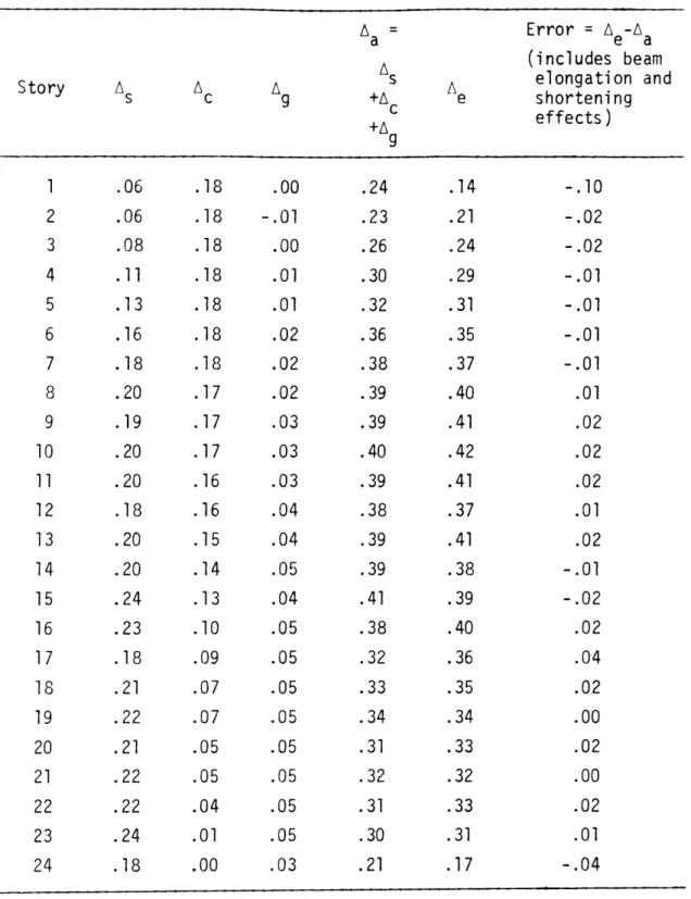
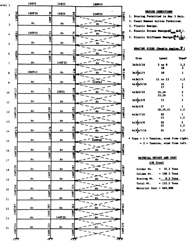
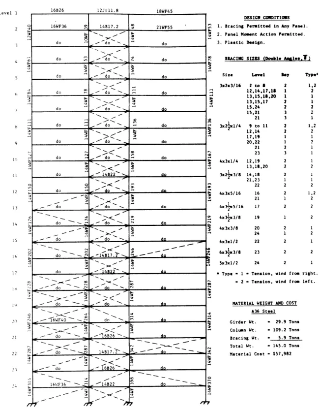
3. Example Problem B2.1A: author's design solution; bracing permitted in bay 3 only; olastic desiqn. 4. Examole Problem B2.1L: Lehigh's design solution; bracinq Dermitted in bay 3 only; plastic design. 5. Examnle Problem B3.1A: author's design solution;
bracing permitted in any bay; plastic design. The twe
-55-ii. Frame C, All A36 Steel, Braced Frames Only.
6. Example Problem C1.1A: author's design solution;
7. 8. 9. 10. 11. 12. 13. 14. 15. 16. 17.
bracing permitted in bay 3 only; plastic design. Example Problem C1.1L: Lehigh's design solution; bracing permitted in bay 3 only; plastic design. Example Problem C1.2A: author's design solution; bracing permitted in bay 3 only; total design. Example Problem C2.1A: author's design solution; bracing permitted in any bay; plastic design. Example Problem C2.2A: author's design solution; bracing permitted in any bay; total design. Example Problem C3.1A: author's design solution; bracing permitted in bay 1 only; plastic design. Example Problem C3.2A: author's design solution; bracing permitted in bay 1 only; total design. Example Problem C4.1A: author's design solution; bracing permitted in bay 2 only; plastic design. Example Problem C4.2A: author's design solution; bracing permitted in bay 2 only; total design. Example Problem C5.1A: author's design solution;
bracing permitted in bays 1 and 3 only; plastic design. Example Problem C5.2A: author's design solution;
bracing permitted in bays 1 and 3 only; total design. Example Problem C6.1A: author's design solution;
oermitted (i.e. all shear in plastic resisted by bay 3 vertical cantileve plastic design.
18. Examole Problem C6.2A: author's desi bracina nermitted in bay 3 only (i.e plastic design oart resisted by bay cantilever truss); total design. iii. Frame C, A441 Steel for All Columns in S
A36 Steel Elsewhere, Braced Frames Only.
design part r truss); an solution; . all shear in 3 vertical tories 13 to 24,
19. Example Problem C7.1A bracing 20. Example bracing 21. Example permitted in Problem C7.1L oermitted in Problem C7.2A bracing oermitted in iv. Frame C, All A36 Steel,
Constraint.
22. Example Problem C8.1A bracina permitted in
beam deoth = 17 in.;
23. Example Problem C8.2A bracing oermitted in
beam depth = 17 in.; v. Frame C, A441 Steel for
A36 Steel
: author's design solution;
bay 3 only: plastic design.
: Lehigh's design solution; bay 3 only; olastic design. author's design solution; bay 3 only; total design. 3raced Frames, Beam Depth
: author's design solution: bay 3 only: maximum allowable )lastic design.
: author's design solution; bay 3 only- maximum allowable total design.
All Columns in Stories 11 to 24, Elsewhere, Unbraced Frames Only.
24. Example Problem C9.1A: author's design solution; unbraced; olastic design.
-57-25. Example Problem C9.1L: Lehigh's design s
unbraced; plastic design.
26. Example Problem C9.2A: author's design s
unbraced; total design.
vi. Frame C, All A36 Steel, Unbraced Frames Only 27. Example Problem C10.1A: author's design
unbraced; plastic design.
28. Example Problem C10.2A: author's design
unbraced; total design.
olution;
olution;
solution;
solution;
2.4 General Discussion of Results.
This section presents general results illustrating the
practicality and efficiency of the proposed design system. Included in the presentation are direct comparisons between the author's design solutions and Lehigh's design solutions, the effects of the beam depth constraint on a selected author's design solution, and a comparison between a braced frame with no restriction on brace location and several other braced frames with restricted bracing patterns. In addition, Tables 2.1 through 2.5 summarize the results for all example
problems.
2.4.1 Comparisons Between the Author's and Lehigh University's Design
design
Solutions.
Five comparisons are made between the author's and Lehigh's solutions.
1. Comparison with Lehigh University Frame B, Unbraced, All A36 Steel.
Lehigh's design solution, B1.1L, and the author's design solution, B1.1A, are illustrated in Figs. 2.4 and 2.3, respectively. In both of these examples only the plastic design constraints are considered. Note that the total material weight according to the Lehigh design is 0.5 per cent lighter than the author's design. This is due to the fact that Lehigh's total girder weight is based on clear snan lengths while the author's total girder weight is based on nominal joint center to joint center girder lengths. In fact, when nominal girder lengths are used to calculate the girder weights of Lehigh's design, the author's design solution is 1.5 per cent lighter.
The author's design required six cycles to satisfy the P-A convergence criterion. The execution time was 48.1 seconds.
2. Comparison with Lehigh University Frame B, Braced, All A36 Steel.
Lehigh's design solution, B2.1L, and the author's design solution, B2.1A, are illustrated in Figs. 2.6 and 2.5, respectively. In both of these examples only the plastic design constraints are considered. Note that in the author's design, no braces have been olaced in the too story. This occurs since the author's design Dermits shear to be resisted by unbraced panels as described in Chanter 3. The design indicates that it is more economical to resist