HAL Id: hal-00824640
https://hal.archives-ouvertes.fr/hal-00824640
Submitted on 22 May 2013
HAL is a multi-disciplinary open access
archive for the deposit and dissemination of
sci-entific research documents, whether they are
pub-lished or not. The documents may come from
teaching and research institutions in France or
abroad, or from public or private research centers.
L’archive ouverte pluridisciplinaire HAL, est
destinée au dépôt et à la diffusion de documents
scientifiques de niveau recherche, publiés ou non,
émanant des établissements d’enseignement et de
recherche français ou étrangers, des laboratoires
publics ou privés.
Broadband converging plasmon resonance at a conical
nanotip
Yunshan Wang, Franck Plouraboué, Hsueh-Chia Chang
To cite this version:
Yunshan Wang, Franck Plouraboué, Hsueh-Chia Chang. Broadband converging plasmon resonance
at a conical nanotip. Optics Express, Optical Society of America - OSA Publishing, 2013, vol. 21,
pp.6609-6617. �10.1364/OE.21.006609�. �hal-00824640�
This is an author-deposited version published in :
http://oatao.univ-toulouse.fr/
Eprints ID : 8538
To link to this article : DOI:10.1364/OE.21.006609
URL :
http://dx.doi.org/10.1364/OE.21.006609
O
pen
A
rchive
T
OULOUSE
A
rchive
O
uverte (
OATAO
)
OATAO is an open access repository that collects the work of Toulouse researchers and
makes it freely available over the web where possible.
To cite this version :
Wang, Yunshan and Plouraboué, Franck and Chang, Hsueh-Chia
Broadband converging plasmon resonance at a conical nanotip
.
(2013) Optics Express, vol. 21 (n° 5). pp. 6609-6617. ISSN
1094-4087
Any correspondence concerning this service should be sent to the repository
administrator:
[email protected]
Broadband converging plasmon
resonance at a conical nanotip
Yunshan Wang1, Franck Plouraboue,2and Hsueh-Chia Chang1,∗1Department of Chemical and Biomolecular Engineering, University of Notre Dame,
Notre Dame, Indiana 46556, USA
2Universit de Toulouse, INPT, UPS, IMFT (Institut de Mcanique des Fluides de Toulouse),
Alls Camille Soula, F-31400 Toulouse, France and CNRS, IMFT, F-31400 Toulouse, France ∗
Abstract: We propose an analytical theory which predicts that Converging Plasmon Resonance (CPR) at conical nanotips exhibits a red-shifted and continuous band of resonant frequencies and suggests potential applica-tion of conical nanotips in various fields, such as plasmonic solar cells, photothermal therapy, tip-enhanced Raman and other spectroscopies. The CPR modes exhibit superior confinement and ten times broader scattering bandwidth over the entire solar spectrum than smooth nano-structures. The theory also explicitly connects the optimal angles and resonant optical frequencies to the material permittivities, with a specific optimum half angle that depends only on the real permittivity for high-permittivity and low-loss materials.
References and links
1. V. Ferry, J. Munday, and H. Atwater, “Design considerations for plasmonic photovoltaics,” Adv. Mater. 22, 4794–4808 (2010).
2. X. Lu, M. Rycenga, S. Skrabalak, B. Wiley, and Y. Xia, “Chemical synthesis of novel plasmonic nanoparticles,” Annu. Rev. Phys. Chem. 60, 167–192 (2009).
3. C. Lee, S. Bae, S. Mobasser, and H. Manohara, “A novel silicon nanotips antireflection surface for the micro sun sensor,” Nano Lett. 5, 2438–2442 (2005).
4. A. R. Parker and H. E. Townley, “Biomimetics of photonic nanostructures,” Nat. Nanotechnol. 2, 347–353 (2007). 5. A. V. Goncharenko, H. C. Chang, and J. K. Wang, “Electric near-field enhancing properties of a finite-size metal
conical nano-tip,” Ultramicroscopy 107, 151–157 (2007).
6. X. Huang, I. H. El-Sayed, W. Qian, and M. A. El-Sayed, “Cancer cell imaging and photothermal therapy in the near-infrared region by using gold nanorods,” J. Am. Chem. Soc 128, 2115–2120 (2006).
7. R. Rodriguez-Oliveros and J. A. Sanchez-Gil, “Gold nanostars as thermoplasmonic nanoparticles for optical heating,” Opt. Express 20, 621–626 (2012).
8. A. Mohammadi, F. Kaminski, V. Sandoghdar, and M. Agio, “Fluorescence enhancement with the optical (bi-) conical antenna,” J. Phys. Chem. C 114, 7372–7377 (2010).
9. H. Shen, N. Guillot, J. Rouxel, M. de la Chapelle, and T. Toury, “Optimized plasmonic nanostructures for improved sensing activities,” Opt. Express 20, 21278–21290 (2012).
10. A. F. Stevenson, “Solution of electromagnetic scattering problems as power series in the ratio (dimension of scatter)/wavelength,” Appl. Phys. Lett. 24, 1134–1141 (1953).
11. M. I. Stockman, “Nanofocusing of optical energy in tapered plasmonic waveguides,” Phys. Rev. Lett. 93, 137404 (2004).
12. A. Goncharenko, J. K. Wang, and Y. C. Chang, “Electric near-field enhancement of a sharp semi-infinite conical probe: Material and cone angle dependence,” Phys.Rev.B 74, 235442 (2006).
13. J. M. Pitarke, V. M. Silkin, E. V. Chulkov, and P. M. Echenique, “Theory of surface plasmons and surface-plasmon polaritons,” Rep. Prog. Phys 70, 1–87 (2007).
14. L. Novotny and S. J. Stranick, “Near-field optical microscopy and spectroscopy with pointed probes,” Annu. Rev. Phys. Chem. 57, 303–331 (2006).
15. Y. Kawata, C. Xu, and W. Denk, “Feasibility of molecular-resolution fluorescence near-field microscopy using multi-photon absorption and field enhancement near a sharp tip,” J. Appl. Phys. 85, 1294–1301 (1999). 16. P. B. Johnson and R. W. Christy, “Optical constants of the nobel metals,” Phys. Rev. B 6, 4370–4379 (1972). 17. F. Wang and Y. Shen, “General properties of local plasmons in metal nanostructures,” Phys. Rev. Lett. 97,
206806 (2006).
18. N. A. Issa and R. Guckenberger, “Optical nanofocusing on tapered metallic waveguides,” Plasmonics 2, 31–37 (2007).
1. Introduction
Surface plasmon resonance on metallic nanostructures has been extensively studied recently in their potential application in solar cell, photothermal therapy, etc. Conical nanotips have been shown to achieve better performance in the above mentioned fields, compared to smooth nanos-tructures like nanospheres. In solar cell application, metallic nanospheres are commonly used to enhance light absorption [1]. However, the narrow resonance spectrum of metallic nanospheres, with a limited bandwidth of about 100 nm [2], restricts the frequency range of light that can be absorbed from the entire solar spectrum (400 nm to 1200 nm). Conical nanotips have realized broadband absorption in experimental and numerical efforts [3–5], thus improving solar cell efficiency. Although broad bandwidth adsorption at the gold tip does not contribute to current generation directly, the plasmonics are scattered from the tip into the photovoltaic material. Metallic nanostructures, due to the intense and localized heat generated at plasmon resonant frequency, are suitable for cancer photothermal therapy. And it is desirable to shift resonant frequency from visible range to near infrared (NIR) range to reduce light absorbed by intrinsic chromophores in native tissue [6]. Simulation and experimental results have shown that nan-otips can excite red-shifted plasmon resonance without compromising the intensity compared to gold nanospheres [7–9]. The same red-shifted broad bandwidth plasmonic excitation also suggests that multi-spectral Raman and other optical near field spectroscopy techniques can be enhanced by a conical tip.
However, a closed-form analytical theory for broadband resonance at conical nanotips that is able to quantify the bandwidth and capture the underlying mechanisms is still lacking. Existing theories failed to capture the intrinsic features of CPR due to their invalid assumptions when dealing with singular geometries. Quasi-static (long wavelength perturbation) theory [10] is frequently used to determine the plasmonic frequency of nanostructures in the literature, par-ticularly for nanospheres, but this theory does not apply for sharp geometries with significant wavelength compression. Slender body WKB theory [11] that models a singular cone with a cylinder with a slowly varying diameter does not describe the crucial EM azimuthal field in-teraction around the tip of the cone and fails to capture its broadband resonance spectrum. Although a closed-form dispersion relation was given in [12], further analysis is lacking to ex-plicitly relate broadband resonance and red-shifted resonance wavelength to material dielectric properties.
This Letter reports a rigorous analysis of the CPR resonance spectrum on conical nanotips. Our theory unveils the singular behavior of CPR on conical nanotips in the near field, captures its unique broadband resonance property and explicitly relates the resonance frequency and op-timum angle to the material dielectric property. With our theory, an optimized cone is shown to have resonance frequency red-shifted and scattering spectra that span the entire solar spectrum, ten times that of a nanosphere.
2. Method description
2.1. Derivation of dispersion relationship
We solve the full Maxwell equations for localized EM field at the tip of an infinite long cone in spherical coordinate, where the origin of the coordinate resides at cone tip, as shown in the inset of Fig. 1(a). The apex angle of the cone is 2α and the cone is made of a material with a complex permittivityεm and a permeability µm surrounded by a dielectric medium with a real permittivityεo and a permeability µo, as depicted in the inset of Fig. 1(a). For the TM (transverse magnetic) mode with a magnetic field in the angular direction, the non-zero com-ponents of the EM fields are Hφ, Er, Eθ, and the full set of Maxwell equations are simplified to
a single scalar equation∇2H
φ−Hφ/(r2sin2θ) +β2
jHφ= 0, whereβ2j =ω2µjεj( j= m, o),ω is the frequency of the incoming light, which is the same for the CPR resonance. The radially confined harmonics within the cone-like tips (0<θ <α) are AmυJυ+1
2(βmr)P 1 υ(cosθ)r− 1 2 (υ is the eigenvalue), Jυ+1 2(β
r) is the Bessel function of the first kind and P1
υ(cos(θ)) is the
as-sociate Legendre polynomial of the first kind. The corresponding harmonics for the dielectric (α<θ<π) are AoυJυ+1
2(βor)P
1
υ(cos(π−θ))r−
1
2. Note that two types of Legendre
polyno-mials are chosen for the two media to satisfy the symmetry conditions. Theθ-dependence of the EM field suggests that the EM field does not decay away from the interface, in contrast to the logarithm decay in WKB theory [11]. Applying the continuity of the field and displace-ment on the interface Hφm|θ =α = Hφo|θ =α, Erm|θ =α = Ero|θ =α (Er= (∇ × H)r/(−iωε)) and
εmEθm=εoEθo (Eθ = (∇ × H)θ/(−iωε)) and omitting higher order less singular plasmonic
modes, a transcendental CPR dispersion relationship is obtained for the dominant eigenvalue υ, with g(α,υ) = f(π−α,υ) fθ(α,υ)
f(α,υ) fθ(π−α,υ), f(θ,υ) = P
1
υ(cosθ) sinθ and fθ(θ,υ) =∂ θ∂ f(θ,υ)
εm εo +f(π−α,υ) fθ(α,υ) f(α,υ) fθ(π−α,υ) =εm εo + g(α,υ) = 0 (1)
This dispersion relationship, derived using different approaches, is identical to Eq. (6) in [12]. But new underlying mechanism are to be unveiled by conformal map techniques and expansion near singular point, which will be extensively discussed in this letter.
As expected, the symmetry of Eq. (1) atα=π/2 yields the classical planar plasmonic
res-onance conditionεm/εo+ 1 = 0 and the frequency dependence of the complex permittivityεm defines the planar plasmon resonant frequencyωswith this planar resonance condition [13]. For TE (transverse electric) mode, the permittivity ratio in Eq. (1) is replaced by the permeability ratio (This ratio is close to unity for most materials in the optical range and since Re[g(α,υ)]
grows rapidly asα decreases belowπ/2, TE resonance can never be realized [14]). In near field, the radial component of the electric field Erscales as rυ−1 (r is the radial distance from the apex of the cone), while the azimuthal magnetic field Hφ is less singular since it scales as rυ
(υ=υr+ iυi). The restriction that the total EM energy be finite over the entire domain requires that −12<υr< 1 for cones [15]. The position-dependent wave-numberκ=υi/r increases dra-matically as CPR waves propagate toward the tip, which is found to be negative (υi< 0) for the converging waves with speed retardation.
2.2. Conformal mapping of dispersion relationship
Equation (1) defines a conformal map −g(α,υ) from the complexυ space to the complex permittivityεm/εo(εm=εr+ iεi) space for cones (The dielectric permittivityεoof the outside medium will be set to unity for simplicity). The CPR sustainable region (grey area in Fig. 1(a)) is confined within the bold curve (the image ofυr = 1) and the horizontal axis. The point (εm/εo=εro= −g(α, −12)) on the real line of the complex permittivity plane, which is the
5 10 15 20
(a)
ε
i
6
5
4
3
2
1
0
5
0
-5
-10
-15
-20
-25
Infrared
UV
Visible
ε
r
Resonance(b)
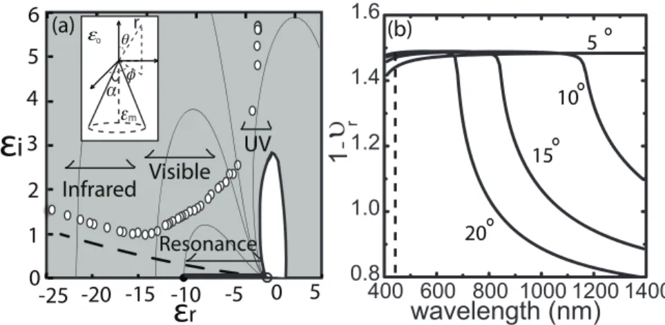
m o rFig. 1. (a) Conformal map in complex permittivities domain. Grey regions shows CPR sustainable region for a cone with half angleα = π/6 and the contour lines correspond
to constantυr. The branch point dg(α, υ)/dυ = 0 of the conformal map is indicated as a solid dot and the limit point (υi→∞) is indicated as an open circle on the negativeεr axis. The bold circular contour is the image ofυr= 1. The hollow circles are empirical permittivities for gold ranging from infrared to ultraviolet wavelength [16] and the dashed curve is the Drude permittivity model for gold [13]. The band of excited frequencies for the Drude model fall at the “resonance” band between the branch point and the limit point on the real axis. (b) Intensification exponents for the Drude gold cone with half angle 5, 10, 15 and 20 degrees are plotted as solid curves. The dotted line marks the resonance peak position of a single nanosphere for comparison [2]. The broad bandwidth extends beyond the visible range for the Drude cone and the resonance frequency is red-shifted compared to gold nanospheres.
image ofυ→ −1
2+ 0i, corresponding to the most singular CPR mode with vanishing wave
numberκ, is a branch point of the conformal map (dg(α,υ)/dυ= 0, marked as a solid circle
in Fig. 1(a)). Another limit point (εr= −1,εi= 0,marked as an open circle in Fig. 1(a)) of the conformal map corresponds to the common largeυrlimit for the pure dielectric (the image of the most singular mode with infinite imaginary partυ→ −1
2+ i∞).
Maximum EM field intensification occurs at the real permittivity axis from the branch point to the limit point (εro<εr< −1). The gold permittivity data of classical Drude free electron theory [13] is plotted as a dashed line in Fig. 1(a), whose imaginary permittivity decreases monotonically with frequency. At high frequency whereεi∼0 and when maximum possible intensification occurs, CPR of Drude conical nanotips hence exhibits a continuous band of res-onant frequencies, whose corresponding real permittivies vary fromεroto -1. This continuous broad band of resonant frequency is unique to conical nanotips due to their continuous change of length scale, while finite length scale of smooth nanoparticles only exhibits discrete and sharp resonance frequency. The intensification exponents 1 −υr computed from Eq. (1) for a Drude gold cone are shown as solid curves in Fig. 1(b) for different angles and wavelengthsλ of incident light. The entire solar spectrum is excited at small angles. In contrast, the extinction spectrum for a single nanosphere [2] has a bandwidth that is 1/10 of the broadband CPR spec-trum for conical nanotips. Empirical gold permittivity data which includes conduction loss due to electron interband transition [16] are also inserted as open circles in Fig. 1(a). The imagi-nary (loss) permittivity of gold exhibits a minimum with respect to frequency which suggests a global resonant frequency for these metals instead of the continuous band of resonant
frequen-wavelength (nm)
half angle (degree)
1.4 1.428 1.3 1.3 1.1
600
800
1000
1200
1400
1600
1800
5
10
15
20
25
30
35
1.428(b)
600 800 1000 1400 0.8 1.0 1.2 1.4 wavelength (nm)(a)
wavelength (nm)Fig. 2. Constant intensification exponent contours lines (1 −υr= 1.428, 1.4, 1.3, 1.1) for a gold cone for empirical permittivities from [16], with different angles and incident light wavelengths, where the dashed curve connects the local resonant conditions from large an-gles until the global optimal angle (circle). The inset (a) plots the intensification exponent for a gold cone with different cone angles (α = 5o, 10o, 15o, 20o, 30o) and shows the CPR spectrum broadens and exhibits a red shift away from the planar plasmon resonant wave-lengthλs= c/ωs. The inset (b) plots the ratio of the imaginary to real permittivity for gold as a function of wavelength [16], where maximum intensification occurs atλ = 892nm.
cies for Drude-type metals. Nevertheless, the scattering feature of the cone still suggests a large bandwidth of excited/scattered light around the global resonant frequency.
2.3. Global resonance frequency
As field focusing at small cone angles can increase both the field intensity and also the conduc-tive loss, an optimal angle is expected. Conversely, the ratio −εi/εrof the material determines the energy loss-storage ratio of the system [17], thus should determine the global resonant fre-quency discussed above. Contour lines of constant EM field intensification exponent 1 −υr computed from Eq. (1) for a gold cone with the permittivity model of [16] are shown in Fig. 2 for different angles and wavelengthsλ of incident light. A global maximum in the intensifica-tion exponent exists atλ = 892nm andα = 11o. As expected, this global resonant frequency resides at the minimum energy loss-storage ratio of gold, as shown in Fig. 2(b). The dash line connects local resonant frequency for different angles which ends at the global optimal angle. The resonance spectrum for a gold cone at different cone angles is shown in Fig. 2(a).
2.4. Asymptotic expansion
2.4.1. Branch point
Asymptotic behavior of g(α,υ) in the limit of low conduction loss (εi/εr→0) is most relevant for both Drude-type and other metals at the IR and visible frequency range. The five curves in the complexυ plane shown in the inset of Fig. 3 are the loci of the dominant eigenvalues as a function of the half-angleα for a cone withεr= −182 and for five different imaginary permittivitiesεi= 0.01, 0.5, 1, 3 and 10. Optimal angles for eachεi, marked as solid circles
on the root loci, follows a horizontal line, which indicates that the optimal angles are only a function ofεrfor metal with low conduction loss. This invariance to conduction loss is due to a curious asymptotic behavior of the dominant eigenvalues in the no-loss dielectric limit. Their smooth loci in Fig. 3 approach the real line on left half plane (υr < 0,υi= 0) and a vertical line (υr= −12andυi< 0) at the pure dielectric limit ofεi→0, with the intersection of the two orthogonal lines occurring atα=α∗
. This intersection of the two lines atυ= −1/2 andα=α∗
is the image of the branch point(εr,εi) = (εro, 0). Given the wavelength of incident light and the material property, the branch point angleα =α∗
can be obtained from dg/dα(α∗
, −1/2) =
0. A leading order asymptotic estimate of the branch-point angleα∗for pure dielectric with
|εr| & 1, leads to the following explicit relation
εr=
8
α∗2ln(α∗/8) (2)
However,α∗
is not the optimum half angle for the zero-loss dielectric. The above asymptotic limit, shown as a bold line in Fig. 3, is actually the upper bound of a continuous range of optimum angles for metal with zero loss–all angles smaller thanα∗
can sustain plasmon waves with the maximum amplitude -1/2 for the eigenvalueυr. Also, the resonance bandwidth (related toυr) can be estimated, given this range of half cone angles. The change of optimal angle from a discrete value for finiteεito a continuous band forεi= 0 is reflected by the contortion of the smooth loci to a kink singularity connecting two straight lines in Fig. 3. Specific and discrete optimum angles for metal with low but finite loss (εi> 0) are depicted as solid circles in the inset and they can be better estimated by another critical pointυo= −1/2 +υioi atα=αowith a constant asymptote for the imaginary exponentυi< 0.
2.4.2. Critical point
The optimum angle at a particular frequency can be obtained by solving Eq. (1) and optimal condition dυr/dα = 0 simultaneously at the limit ofεi/εr→0 andεr/εo→ −∞. Restricting ourselves to regions close to the critical point, an explicit Taylor expansion about the critical point can be carried out to yieldυr+ 1/2 = −iεi/gυ(αo,υo). The optimal condition then re-duces to goα−goυgoυα/go
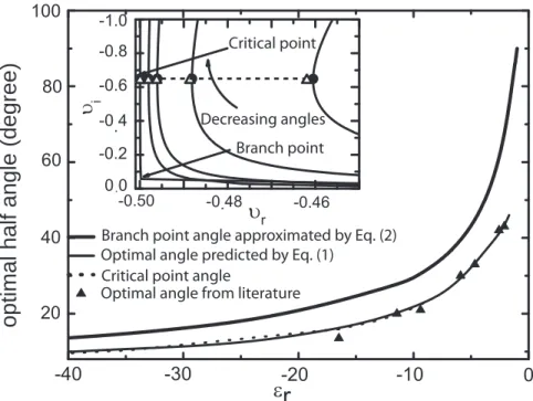
υυ= 0. Combination of this criterion and Eq. (1) (εi= 0) gives rise to the optimal angleαoand the correspondingυiofor any givenεr. Good agreement between the optimal angles predicted by Eq. (1) (solid curve in Fig. 3), critical local resonance points (dotted curve in Fig. 3) and numerical data from [18] is observed in a large range of optical excitation frequency that yields a range ofεrbetween -200 and -2. Independent ofεi, both the branch point angles and critical point angles approach zero at the largeεrlimit.
It can be shown that, for finite loss and at the limit ofεr/εo→ −∞, iεr/gυ(αo,υo) approaches a constant and henceυr+ 1/2 ∼ −0.693(εi/εr). This estimate of the dominant exponent at optimal angles for each frequency confirms that the global resonant frequency occurs at the minimum of the loss-storage ratio in Fig. 2(b). It also allows a convenient estimate of the local and global resonant frequencies from the material properties(εi/εr)(ω). As seen in Fig. 3, both the predicted exponent and optimum angle at a particular real permittivity are in good agreement with numerical values from Eq. (1).
3. Comparison with numerical results
Intensification exponent calculated from Eq. (1) can be compared to simulation data published in the literature [18]. Knowing|Er| ∼ rυr−1, we obtain the dependence of the ratio of the electric field intensity on the exponents and the geometry Etip/Eo= (r1/r2)υr−1, where r1is the radial
distance from the apex of the cone to the point where Etip is measured and r2 is the radial
Branch point angle approximated by Eq. (2) Optimal angle predicted by Eq. (1)
Critical point angle
Optimal angle from literature
optimal half angle (degree)
Branch point Decreasing angles Critical point
Fig. 3. Optimum angles of a gold cone at differentεrcorresponding to different excitation wavelength. Simulation data from the solution of the Maxwell equation [18] are compared to estimates from the branch point, the critical point and the exact solution of the CPR dis-persion relationship Eq. (1). The inset depicts the dominant CPR intensification exponent as a function of the half angle for five imaginary permittivitiesεi= 0.01, 0.5, 1, 3 and 10.0 atεr= −182. The optimum angle yielding the most negative υris computed numerically for eachεiand is marked as a solid circle on each root locus. Analytical estimate, with a
εi/εrscaling, from an expansion about the critical point is shown as open triangles. At the limit ofεi/εr→0, the eigenvalue of this optimum angle approaches the critical point at
υo= −1/2 + υioi.
From simple geometry, r1=sinαR1 and r2=sinαR2 where R1=5 nm is the radius of curvature of
the apex and R2=300 nm is the radius of the cylindrical wire at the far end. Figure 4 favorably
compares the literature data log10(Etip/Eo) to our analytical estimate (υr−1) log10(R1/R2),
(b)
half angle (degree)
Gold
(a)
half angle (degree)
Fig. 4. (a) Comparison of theoretical intensification factor(υr−1) log10(R1/R2) (solid
curves) against the literature values of [18] (scattered points) for gold cones of different an-gles (R1=5 nm, R2=300 nm). (b) Comparison against literature data [18] for three different materials at excitation wavelength 488 nm with the same R1 and R2.
4. Conclusion
In conclusion, we have provided an analytical theory that explains the underlying mechanism of red-shifted resonance wavelength and broadband CPR spectrum at conical nanotips. Our theory predicts a continuous band of resonant frequencies for Drude-type metals and a global resonant frequency for metals with electron interband transition. Asymptotic local analysis of the CPR dispersion relation offers simple estimates of the optimal angles and resonant frequen-cies for materials with low loss. Intensification exponents calculated from the CPR dispersion relation are favorably compared with published simulation results. Our theory suggests that conical nanotips are ideal scattering centers for enhancing light absorption in solar cells, due to its broadband resonance and strong EM field intensity. Its red-shifted resonate bandwidth are also desirable for cancer photothermal therapy, multi-spectral Raman and other near-field spectroscopy techniques.
Acknowledgments
HCC acknowledges support from NSF Grant IDBR0852741. Helpful discussions with L-J Cheng and S. Monnieux are gratefully acknowledged.
![Fig. 2. Constant intensification exponent contours lines (1 − υ r = 1.428,1.4,1.3,1.1) for a gold cone for empirical permittivities from [16], with different angles and incident light wavelengths, where the dashed curve connects the local resonant conditio](https://thumb-eu.123doks.com/thumbv2/123doknet/14308915.495063/7.918.220.705.97.388/constant-intensification-exponent-contours-empirical-permittivities-different-wavelengths.webp)
![Fig. 4. (a) Comparison of theoretical intensification factor (υ r − 1) log 10 (R1/R2) (solid curves) against the literature values of [18] (scattered points) for gold cones of different an-gles (R1=5 nm, R2=300 nm)](https://thumb-eu.123doks.com/thumbv2/123doknet/14308915.495063/10.918.280.640.202.782/comparison-theoretical-intensification-factor-against-literature-scattered-different.webp)
