HAL Id: hal-01223506
https://hal.archives-ouvertes.fr/hal-01223506
Submitted on 2 Nov 2015
HAL is a multi-disciplinary open access
archive for the deposit and dissemination of
sci-entific research documents, whether they are
pub-lished or not. The documents may come from
teaching and research institutions in France or
abroad, or from public or private research centers.
L’archive ouverte pluridisciplinaire HAL, est
destinée au dépôt et à la diffusion de documents
scientifiques de niveau recherche, publiés ou non,
émanant des établissements d’enseignement et de
recherche français ou étrangers, des laboratoires
publics ou privés.
Multilevel (3D) lab on chip for implementing
reconfigurable magnetophoretic functionnalities
Marc Fouet, Sébastien Cargou, Rémi Courson, Xavier Bouquet, Ludovic
Salvagnac, Anne Marie Gué
To cite this version:
Marc Fouet, Sébastien Cargou, Rémi Courson, Xavier Bouquet, Ludovic Salvagnac, et al.. Multilevel
(3D) lab on chip for implementing reconfigurable magnetophoretic functionnalities. Transducers 2015,
Jun 2015, Anchorage, United States. pp.529 - 532, �10.1109/TRANSDUCERS.2015.7180977�.
�hal-01223506�
MULTILEVEL (3D) LAB ON CHIP FOR IMPLEMENTING RECONFIGURABLE
MAGNETOPHORETIC FUNCTIONNALITIES
M. Fouet
12, S. Cargou
12, R. Courson
12, X. Bouquet
12, L. Salvagnac
12, and A.M. Gué
121
CNRS, LAAS, Toulouse, FRANCE
2Université de Toulouse, Toulouse, FRANCE
ABSTRACT
This study demonstrates the integration of a multilevel magnetophoretic lab on chip: combining 3D fluid engineering and localized magnetic actuation enables the full integration of a cell tagging and magnetic separation device. A system performing magnetic handling of beads at cell resolution was also devised based on the same technologies.
KEYWORDS
3D Microfluidics, Magnetic actuation, Micro-coils, Mixing, Cell tagging
INTRODUCTION
Super paramagnetic microbeads are broadly used in biological applications (cell separation, immuno-precipitation…) and magnetophoresis has been frequently implemented in lab on chip systems [1]. While molecular mixing in microfluidics has been thoroughly studied, carrying out labeling of cells or biological species on-chip remains a challenge. Three-dimensional microfluidics is helpful to perform this step, as we show targeting with magnetic microbeads could be achieved on cells (monocytes) with a 3D micromixer.
For magnetic actuation, permanent magnets present the advantages of a strong magnetic field, however if they are the only source of magnetic field, the latter is consequently steady and non-local. This prohibits the integration of a large range of functions like on-chip magnetic labeling, actuation at cell resolution with attraction and repulsion possibilities, or more exotic functions such as focusing, and any coupling of functions.
Standard microfabrication processes allow us to integrate micro-coils inside microfluidic chips. Those coils can be used as single sources of magnetic field, or it is possible to combine them to permanent magnets: using both enables to have high values of magnetic field available, and high values of the field gradient, leading to an increased magnetic force.
Design considerations
Micro-particles and cell mixing was achieved with a three-dimensional micromixer whose design is based on baker’s transformation [2].
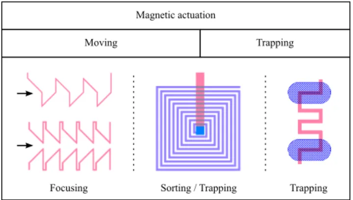
Various designs and functions were tested for magnetic actuation. We built hybrid systems including external permanent magnets for the generation of a high and homogenous magnetic field that we coupled with integrated
micro-coils producing locally a high gradient. Those systems were used to perform focusing (two designs) and trapping (Figure 1). Other devices using micro-coils only were devised for trapping and vertical sorting.
Magnetic actuation
Trapping Moving
Focusing Sorting / Trapping Trapping
Figure 1: Left: Two designs for focusing using 1 or 2 single level micro-coils (external magnets needed). Center: Planar spiral coil to perform vertical sorting and trapping (the coil center is connected from below, number of turns: 10). Right: Localized trapping/release device (external magnets needed). The blue pillars aim at guiding the cells and particles to the trapping device (“2” shape). For all the designs, the dimensions of the wires carrying the electrical current are width = height = 5 µm.
EXPERIMENTAL
Microfabrication
The lab on chip was manufactured using a powerful lamination technique enabling 3D microfluidic structures and micro-coils integration. We used a low cost, commercially available dry film DF-10XX series (EMS) that fits microfluidic requirements and gives the possibility to build easily 3D microfluidic structures [3]. DF films are ten times cheaper than SU8 and TMMF, are compatible with most of standard microfabrication technologies and their processing time is three times faster. Therefore this low-cost material combined with multilevel lamination process allows introducing massively 3D microfluidics in active lab on chip.
A 4” glass substrate (Schott AF32, 500 µm thickness) was chosen to facilitate the chip visualization and integration afterwards. Same structures and results could be obtained with this process on silicon wafers.
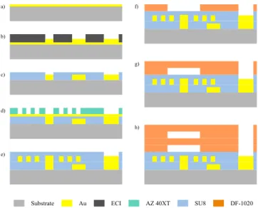
The core process for manufacturing the micro-coils is a succession of Ti/Au (50/50 nm) metal deposition and electroplating (Au or Cu, 5 µm) in an AZ-40XT positive photoresist mold (14 µm), as shown in Figure 2 d). Seed layer is removed, and micro-coils are then encapsulated
(thus insulated) with a 10 µm SU8 layer (e). In case the micro-coil is a spiral and needs electrical connection in its center, additional steps to create the 3D network of wires are required before (using the same process with lower thickness and ECI photoresist: a) to c)).
The 3D microfluidic channels are then created on top of the protected micro-coils with dry film lamination. DF-1020 are 20 µm thickness epoxy based dry films, and show a very good adhesion on SU8 layers. Surface treatment (O2 plasma,
200W for 2 min) was used prior to lamination. A Shipley 3024 laminator was used with the following parameters from the second layer of dry film: T = 65°C, 2.1 bars pressure and 1 m/min roll speed.
After removal of protection films, the laminated layer was exposed to 365 nm wavelength light (240 mJ/cm2 for
20 µm layers) in a mask aligner (SUSS MicroTec MA-6 and MA-150). Post exposure bake was performed on a programmable hotplate (5 to 7 mins at 100°C with 10°C/min increase) to avoid deforming the channels due to the trapped air or to residual stress. Cyclohexanone was then used as a developer, with increased developing time as the fluidic layers pile on.
A final hardbake (2 mins at 125°C) is then applied to ensure removal of all solvents, and thus chemical resistance and best biocompatibility. Finally, the 4” wafer is cut with a diamond saw. SU8 AZ 40XT ECI Substrate Au DF-1020 a) b) c) d) e) f) g) h)
Figure 2: Microfabrication process. a) Ti/Au metallization followed by electroplating (2 µm) in a 3 µm ECI mold. c) SU8 (3 µm) encapsulation of the first layer of wires. d) Metallization and electroplating (5 µm) in a 14 µm AZ-40XT mold, followed by a 10 µm SU8 encapsulation. f) Dry film (DF-1020) lamination over encapsulated micro-coils and photolithography steps to form the channels. g)h) Same steps as f) to create a 3D network of microfluidic channels.
The alignment quality and thickness homogeneity for the 3D microfluidic channels can be observed on a cross-sectional view in Figure 5 a).
18 m
m
Electrical pads
Fluid in/outlets
Figure 3: Left: Magnetofluidic chip with single level of wires obtained after microfabrication. Right: SEM image of planar spiral micro-coils (3 coils wired in series, the coils centers are connected below the SU8 insulation layer).
During the process, mechanical profilometer, optical and scanning electron microscopes are used to characterize the height and shape of photoresists and electrical wires (Figure 3). A 4” wafer can fit 12 magneto-fluidic chips (18 x 18 mm2).
Integration
The microfluidic chip has to be connected to a source of electrical current in order to power on the coils, as well as tubing to handle fluids inlets and outltes. Also, in the case of micro-coils that need external permanent magnets, the position of the latter have to be set with precision.
A chip comprises up to 10 micro-coils with independent inlet and outlet: this is a major feature since reversing the current will lead to an attractive or repulsive force in case an external permanent field is used. Electrical connection is established through 20 pads (800 x 800 µm2) on a side of
the chip (Figure 3). A connector with 20 spring-loaded contacts (Mill-Max Mfg. Corp.) placed on a PCB is used to make contact, with a moving stage (Thorlabs), to carry current to and from the current control board (Figure 4).
Fluid handling is achieved with a black Delrin manifold: 5 o-rings are set in compression on the 5 in/outlets of the chip. The manifold is either used with ferrules/nuts and Teflon capillaries (internal diameter 300 µm) or as integrated reservoirs. Microscope lens Permanent magnet Manifold Chip Spring loaded contacts Moving stage
Figure 4: Left: Current control board (on top of an Arduino Mega microcontroller). Right: Aluminum chip holder fixture.
In order to control the electrical current running in each coil, we designed a control board (Figure 4, left), which is plugged onto an Arduino Mega board. The current limit for a single coil is 180 mA (a 5V, 2A power source is needed
for the 10 coils). On the Arduino board, 10 digital pins are used to set the coils on and off, 10 other pins for the current direction, 10 analog pins to read the current intensity from a ampere meter component, and the desired current value is set using a serial port interface between the two boards. A Labview interface is then implemented to program actuation and to have a live feedback of current values.
Experimental setup and material
The chip holder presented on Figure 4 (right) is placed on the top of an inverted fluorescence microscope (Zeiss Axio Observer), and microfluidic channels are observed through the micro-coils (i.e. a trapped bead or cell will be masked by the coil).
Images were obtained in bright field or fluorescence (excitation source: Lumencor), captured with Andor cameras (EMCCD iXon or CMOS Zyla 4.2), and processed with Micro-Manager and ImageJ.
A fluid pressure controller (Fluigent) was used to inject the different solutions and pressurize the chip if needed (filling of 3D micro channels).
Two types of super-paramagnetic beads were used: Invitrogen Dynabeads (4.5 µm diameter), coated with anti-CD14 antibody, and Spherotech fluorescent magnetic particles (8 µm diameter).
We followed ATCC recommendations for THP-1 monocytes culture method (RPMI medium). Monocytes were usually labeled with Hoechst stain (33342) for fluorescence visualization.
RESULTS AND DISCUSSION
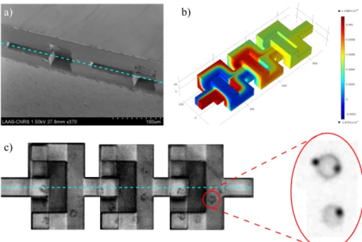
The labeling of white blood cells (monocytes) with superparamagnetic particles was performed “up stream” with a microparticles 3D micromixer while cell separation and manipulation was achieved “downstream”, for instance through a vertical separation stage over integrated microcoils. THP-1 culture monocytes were tagged with magnetic beads coated with anti-CD14 antibody. Simulation results (Figure 5 b) were experimentally verified, and the 3D mixer performs well for molecular (diffusion based) mixing. However, contrary to standard approaches, this solution turned to be well suited to on-chip cellular labeling with an average labeling yield of 1-2 microbead/cell (Figure 5 c).
Cells can thus be magnetically targeted on-chip, and magnetic actuation can be applied right after (achieving therefore a high level of integration).
Planar spiral micro-coils (center design in Figure 1) can be used for vertical sorting, as shown in Figure 6 a). Tagged monocytes trapping and separation efficiencies werestudied at different flow rates for a given electrical current of 100 mA (Figure 6 b). Interestingly we demonstrated an abrupt transition from a “trapping mode” to a “continuous separation mode” depending on flow. On a 3D separation stage, 9 coils are lined up and most of them are used to attract magnetic beads towards the bottom of the channels and closer to the coils to reach a higher efficiency.
c)
a) b)
Figure 5: a) SEM image of a 3D micromixer (cross-sectional view): 2 loops are shown (blue dotted line represents the main channel /cut plan). Device was cut with a diamond saw. b) FEM simulation representing molecular mixing of a fluorescein solution (0.6 mM) with DI water. c) Trajectory of a tagged monocyte (4 magnetic beads attached) inside a mixer unit (3 loops). Zoomed part: other examples of tagged cells with 1 and 2 beads.
The thermal safety of the device has also been checked using rhodamine B (fluorescence signal variation with temperature) to ensure Joule heating will not harm the monocytes. Average measured electrical resistance for the array trapping design (right on Figure 1) is 3.45 Ω for gold, 2.85 Ω for annealed gold, and 2.10 Ω for copper. Copper is thus a preferred material for the coils as the resistance (and thus heating) is lower, although oxidation happens faster (especially after plasma surface treatments).
0 20 40 60 80 0.2 0.5 1 1.5 2 2.5 3
Flow rate (µL/min)
Trapping Separation 100 % Bea d s a) b)
Figure 6: a) Trapped monocytes on a planar spiral coil (magnetically tagged prior to experiment). Image taken with an upright microscope. b) Vertical separation and trapping efficiency of 4.5 µm diameter magnetic beads for different flow conditions. Explanatory schemes of the vertical actuation mechanisms (separation vs. trapping) are included.
Spiral micro-coils showed their potential in term of trapping and separation, but one of the limitations is the size of the magnetic device (typically > 200 µm for 10 turns). With the use of permanent magnets, the whole device is less integrated, but magnetic actuation can be performed with only one wire (left and right designs on Figure 1). Those single wire coils are easier to build (no need for vertical electrical connection), and can have a very localized field of action, down to the size of a single bead.
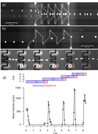
Centering a cell or a bead in a micro-channel can be useful for several applications: transfer to a centered buffer solution, positioning for measurement, etc. This function could be achieved with our two designs (Figure 7 a) and b)). Working in a strong permanent field (40 to 70 mT), we even showed deviation on a small chain of beads. Deviation could be shown for beads velocity up to 2 mm/s.
1 2 3 4 c) d) d) 0 1 2 3 4 5 6 7 8 0 500 1000 1400 t (s) B ead V elocit y (µm/ s) 1 2 3 4 Coil 1 2 3 4 Attraction Repulsion a) 100 µm b) 100 µm
Figure 7: a) Focusing of two single beads (bottom) and a chain of 4 beads with a dual coils system. b) Focusing of a single bead with a mono coil system. c) Trajectory of a bead being trapped and actively released 4 times with a magnetic capture array. d) Diagram of coils actuation command and velocity of the tracked particle. Magnetic beads of 4.5 µm are used in a) and b), fluorescent magnetic particles are used in c) d). Flow direction is left to right in all cases, and current is 100 mA.
We also demonstrated dynamic cell trapping array capabilities with 8µm diameter fluorescent beads (Figure 7 c) and d)). Magnetic traps are based on the attraction of a middle wire and repulsion (or focusing) of side wires. The array consists of 10 columns of 10 traps, and each column is individually addressed. In order to release / expel the particle quickly we inverted the current polarity for a short amount of time. Single bead trapping was performed at velocities above 1 mm/s.
This way we proved that magnetic trapping arrays can be organized dynamically and reversibly. It is therefore possible to manipulate an object or a cell that has been marked with magnetic particles; this technique could open new avenues regarding micromanipulation.
Many of the designs and techniques discussed here paved the way to address specific issues like particles / cells micro-mixing, vertical magnetic sorting using planar spiral micro-coils, and localized magnetic actuation. Deeper investigation of these concepts is necessary and will be beneficial for bringing more powerful and more integrated magnetic handling tools to microfluidics and biology.
ACKNOWLEDGEMENTS
This work was funded by the French National Research Agency (ANR) in the frame of the PIA – Nanobiotechnology project Digidiag, and by the Defense Agency (DGA). We also acknowledge the French Renatech Network for their support.
REFERENCES
[1] A. van Reenen, A. M. de Jong, M. J. den Toonder, M. W. J. Prins, “Integrated lab-on-chip biosensing systems based on magnetic particle actuation – a comprehensive review”, Lab On a Chip, 1966, 14 (2014).
[2] P. Carriere, “On a three-dimensional implementation of the baker’s transformation”, Physics of Fluids, 118110, 19 (2007).
[3] R. Courson, S. Cargou, V. Conedera, M. Fouet, M. C. Blatche, C.L. Serpentini, A.M. Gué, “Low-cost multilevel microchannel lab on chip: DF-1000 dry film photoresist as a promising enabler”, RSC Advances, 54847, 4 (2014).