ةرازو ثحبلا يملعلا ميلعتلاو يلاعلا
MINISTERE DE L’ENSEIGNEMENT SUPEREUR ET DE LA RECHERCHE SCIENTIFIQUE ةعماج دبع ديمحلا نب سيداب مناغتسم
Université Abdelhamid Ibn Badis Mostaganem ةيلك
مولعلا و ايجولونكتلا
Faculté des Sciences et de la Technologie DEPARTEMENT DE GENIE DES PROCEDES
N0 d’ordre : M2/GP/2020
MEMOIRE DE FIN D’ETUDES
DE MASTER ACADEMIQUE
Filière : Génie des procédés
Spécialité : Génie chimique
Thème
Présenté par :
Bilal BELMEKKI
Date de soutenance : 21/06/2020 devant le jury composé de :
Président : ADDOU Ahmed Professeur Université de Mostaganem Examinateur : ABDELMALEK Fatiha Professeur Université de Mostaganem Encadrant : GHEZZAR Mouffok Redouane Professeur Université de Mostaganem
Sensitization phenomena by gliding arc discharge:
Experimental and Modeling study
Dedication
With my deepest feelings of gratitude, I dedicate this modest work to:
my dear parents especially my mother who have always supported and encouraged me throughout my schooling,
my brothers, my sisters, my friends,
Acknowledgments
This master thesis has been carried out at the ‘Laboratory of Sciences et Techniques of Environment and Valorization, Faculty of Sciences and Technology, University of Mostaganem, and directed by Professor F. ABDELMALEK.
I would like to thank the following people for their help, support, guidance and positive critics during this study:
First of all, I would like to thank Allah for blessing me and giving me the good health to finish this work.
Secondly, I would like to thank my supervisor and monitor Mister M.R. GHEZZAR, Professor at the University of Mostagenem for accepting me as his student and trusting me and also for his guidance and the support in this entire work.
Special thank goes to Professor F. ABDELMALEK for accepting me in the laboratory and for her support, and a big thank goes to mister A. ADDOU, Professor at the University of Mostaganem, for his guidance and for sharing his knowledge and experiences which helped me during my work. And those who I enjoyed with, a huge thank goes to Djamel, Amine, Ramzi, Omar, all the
STEVA Team, especially, to those who helped me: big thank goes to Mr. Fouad FERHAT, Ms. Samira SLAMANI and Mr. Ali BELHAINE.
For all my teachers during my career, thank you for helping me and sharing your knowledge and experiences with me.
Finally, I want to express my deep gratitude to my lovely Mum for her support and love. I would have not made it without her moral support and prayers.
List of abbreviations: E Electric field P Pressure
AOP Advanced oxidizing process Atm Atmosphere
C° Celsius Cm Centimeter
LTE Local Thermodynamic Equilibrium DBD Dielectric Barrier Discharge DC Direct Current
e– Electron
GAD, Glidarc Gliding Arc Discharge
GAD.FF Gliding Arc discharge Falling Film
h Hour
L Liter
Te Electron Temperature
Tn Heavy particles Temperature
K Kelven m Meter mg Milligram Min Minute mL Milliliter Mol Mole nm nanometer P Pressure pH Hydrogen Potential
SHE Standard Hydrogen Potential
s Second
µM Micro Mole
V Volume
UV Ultra Violet kV mm1
ACS
Ф Nozzel Diameter Of Plasma Gas e Inter-Electrode Distance
Q Gas Flow Rate L.h⁻¹ d Electrode-Film Distance L Length l Width ɛ Thikness α Angle D Depth Δ Chanel Widths ω Peristaltic Pump
Pp Discharge Pulse Mean Power J Photon Flux
R² Correlation Coefficient εF Fermi Energy Of The Metal Wₒ Metal’s Work Function ns Nanosecond
List of figures:
Figure I.1 (a) Diagrammatic sketch of gliding arc discharge reactor ; (b) photographs of electrical discharge in gliding arc reactor
08
Figure I.2 GAD I diagram (Open cell Reactor) 09
Figure I.3 Schemes of the gliding arc discharge GAD (II) 10
Figure I.4 Schemes of the gliding arc discharge GAD-FF 11
Figure II.1 GAD reactor 1D geometry 30
Figure II.2 Batch GAD reactor-discontinuous mode 31
Figure II.4 Plate GAD reactor-continuous mode 32
Figure II.5 Simulink diagram bloc using all data of table II.1 35
Figure II.6 Concentrations of H⁺, NO₂⁻ and NO₃⁻ ions in water in batch GAD reactor 36
Figure II.7 Concentrations of H⁺, NO₂⁻ and NO₃⁻ ions in water in batch GAD reactor 37
Figure II.6
Computational flow chart 32
SUMMARY
Abstract ... 1
General introduction ... 2
Chapter I: ... 3
Plasmachemistry process ... 3
I.1 Plasma as forth state of matter ... 4
I.2 Manmade plasma ... 4
I.3 Applied plasmachemistry ... 5
I.3.1 Thermal and NonThermal plasma ... 5
I.3.2 Types of discharge in thermodynamic equilibrium ... 6
a) GAD I (open cell): ... 7
b) GAD (II) : ... 8
c) GADFF ... 9
I.4 Factors affecting plasma efficiency: ... 10
I.4.1 Reactor system (geometry): ... 10
I.4.2 Electrode ... 11
I.4.2 Energy input ... 11
I.4.3 Solution pH ... 12
I.4.4 Temperature ... 12
I.4.5 Gas input ... 13
I.6 Plasma products: ... 13
I.6.1 Plasma energy ... 13
a) UV light ... 13
b) Shockwave ... 14
c) Pyrolysis ... 14
d) Electrons: ... 14
I.6.2 Plasma species : ... 16
I.6.3 Plasma reactions ... 17
a) In plasma region: ... 17
b) In liquid region : ... 17
Chapter II: ... 24
Plasma sensitization process modeling ... 24
Introduction ... 25
II.1 Mass transfer ... 25
II.2 Kinetic Model ... 26
II.3 Modeling ... 29
II.3.1 Geometry ... 29
II.4.2 Material Balance ... 29
GAD Batch reactorDiscontinuous mode ... 29
Figure.II.2. Batch ... 30
GAD plate reactor ... 30
Figure.II.3. Plate ... 31
II.4 Results and Discussion ... 31
Figure.II.5. Simulink diagram bloc using all data of table II.1 ... 35
-Abstract:
The aim of this work is to certify the sensitization of organic molecules, a phenomenon related to the cold plasma matter generated by the Gliding Arc Discharge reactor. The study was conducted by an experimentally and validated by modeling-simulation approach using Simulink hardware. The predictive mathematical model used to calculate the plasma species concentrations and the conversion rate of phenol as reactive target was inspired from the model of penetration of gas-liquid reactions. The plasma reaction for few seconds demonstrates that the sensitization phenomena exists despite the mass transfer of protons and nitrous species. Aqueous plasma chemistry offers a novel and significant pathway to sensitize organic molecules to be more reactive by increasing their energy sate.
General introduction
Cold atmospheric-pressure plasma holds great prospects in diverse fields such as environmental protection, biomedicine, nanotechnology, and agriculture. For many of these applications, the targets of plasma treatment are placed in a humid medium, thus subjecting gaseous plasma species to strong interactions with water molecules before their arrival at and reaction with the targets. Many questions remain unanswered to highlight the interaction of plasma species with the liquid medium due to the complexity of the mechanism.
In reality, organic molecules are treated for hours in order to degrade them in water. This aspect is conventional and requires a lot of electrical energy to be applied correctly. There is also another mode of treatment which is the temporal post-discharge which give satisfactory results but require days of post-reaction to degrade the molecule. A last mode of treatment recently tested by the members of the STEVA laboratory (Univ-Mostaganem), has been successfully applied to make organic molecules highly reactive with coagulation and Fenton. It is about sensitization, that is to say the treatment of the aqueous solution for a few seconds in order to prepare it for a possible treatment downstream of the plasma process.
The Understanding of the sensitization phenomenon will help to master the coupled processes with plasma. The latter can be generated by different types of reactors. In this work, we were interested in the Gliding Arc Discharge (GAD) to conceptualize the sensitization process. To properly carry out this task, our memory has been divided into two main parts:
• Part 1: a state of the art on plasma chemistry in order to become familiar with the elementary concepts that we will use in the results part.
• Part 2: The aim is to present the different results of the simulation-simulation by SIMULINK of the absorption of the phenol molecule in water. Each predicted result has been validated by experiments.
Chapter I:
I.1 Plasma as forth state of matter
The Plasma is an ionized gas, a distinct fourth state of matter. “Ionized” means that at least one electron is not bound to an atom or molecule, converting the atoms or molecules into positively charged ions. As temperature increases, molecules become more energetic and transform matter in the sequence: solid, liquid, gas, and finally plasma.
The free electric charges – electrons and ions – make plasma electrically conductive (sometimes more than gold and copper), internally interactive, and strongly responsive to electromagnetic fields. Ionized gas is usually called plasma when it is electrically neutral (i.e., electron density is balanced by that of positive ions) and contains a significant number of the electrically charged particles, sufficient to affect its electrical properties and behavior. In addition to being important in many aspects of our daily lives, plasmas are estimated to constitute more than 99% of the visible universe. The term plasma was first introduced by Irving Langmuir (1928) because the multicomponent, strongly interacting ionized gas reminded him of blood plasma. Langmuir wrote: “Except near the electrodes, where there are sheaths containing very few electrons, the ionized gas contains ions and electrons in about equal numbers so that the resultant space charge is very small. We shall use the name plasma to describe this region containing balanced charges of ions and electrons.” There is usually not much confusion between the fourth state of matter (plasma) and blood plasma; probably the only exception is the process of plasma-assisted blood coagulation, where the two concepts meet.
I.2 Manmade plasma
Plasmas occur naturally but also can be effectively man-made in laboratory and in industry, which provides opportunities for numerous applications, including thermonuclear synthesis, electronics, lasers, fluorescent lamps, and many others. Manmade plasma ranges from slightly above room temperature to temperatures comparable to the interior of stars. Electron densities span over 15 orders of magnitudes. However, most plasmas of practical significance have
electron temperatures of 1 to 20 eV with electron densities in the range 106 to 1018 cm-3. Not all particles need to be ionized in a plasma; a common condition is for the gases to be
partially ionize.
The use of an electric discharge is one of the most common ways to create and maintain a plasma. Here, the energy from the electric field is accumulated between collisions by the electron that subsequently transfers a portion of this energy to the heavy neutral particles through collisions. Even with a high collision frequency, the electron temperature and heavy
particle temperature normally will be different. Because the collision frequency is pressure dependent, high pressures will increase this frequency and the electron’s mean free path between collisions will decrease. One can show that the temperature difference between electrons and heavy neutral particles is proportional to the square of the ratio of the energy an electron receives from the electric field (E) to the pressure (p). Only in the case of small values of E/p do the temperatures of electrons and heavy particles approach each other; thus, this is a basic requirement for local thermodynamic equilibrium (LTE) in a plasma. Additionally, LTE conditions require chemical equilibrium as well as restrictions on the gradients.
When these conditions are met, the plasma is termed a thermal plasma. Conversely, when there are large 1departures from these conditions, Te > Tn, the plasma is termed a nonequilibrium plasma or nonthermal plasma. As an example, for plasma generated by glow discharges, the operating pressures are normally less than 1 kPa and have electron temperatures of the order of 104 K with ions and neutral temperatures approaching room temperatures. Physics, engineering aspects, and application areas are quite different for thermal and nonthermal plasmas. Thermal plasmas are usually more powerful, while nonthermal plasmas are more selective. However, these two different types of ionized gases have many more features in common and both are plasmas.
I.3 Applied plasmachemistry
Both natural and man-made laboratory plasmas are quasi-neutral, which means that concentrations of positively charged particles (positive ions) and negatively charged particles (electrons and negative ions) are well balanced. Langmuir was one of the pioneers who studied gas discharges and defined plasma to be a region not influenced by its boundaries. The transition zone between the plasma and its boundaries was termed the plasma sheath. The properties of the sheath differ from those of the plasma, and these boundaries influence the motion of the charged particles in this sheath. The particles form an electrical screen for the plasma from influences of the boundary.
I.3.1 Thermal and Non-Thermal plasma
All varieties of plasma systems are traditionally defined into two major categories, namely thermal and non-thermal, in terms of electronic density or temperature [1]. In general, a subdivision can be made between plasmas which are in thermal equilibrium and those which are not in thermal equilibrium. Thermal equilibrium implies that the temperature of all species (electrons, ions and neutral species) is the same. This is, for example, true for stars, as well as
for fusion plasmas. High temperatures are required to form these equilibrium plasmas, typically ranging from 4000 K (for easy-to-ionize elements, such as cesium) to 20 000 K (for hard-to-ionize elements, like helium). Often, the term ‘local thermal equilibrium’ (LTE) is used, which implies that the temperatures of all plasma species are the same in localized areas in the plasma.
I.3.2 Types of discharge in thermodynamic equilibrium
In the application of electrical plasma technology for water treatment, designing an energy-efficient plasma reactor has been receiving great attentions. In addition, a variety of different reactors with liquid phase or gas–liquid phase electrical discharges for phenol and phenolic compounds removal have been reported by several authors [2]. In particular, the plasma-treatment of liquids can be applied using buy: gliding arc discharge (GAD), dielectric barrier dielectric (DBD) and corona discharge. In this section, we will detail only the first type of the discharge.
The gliding arc discharge (GAD) is considered as an innovative technology exhibiting a dual character of thermal and non-thermal plasma and a typical reactor, as shown in Figure I.1.a, consists of insulating cover, ‘‘knife-edge’’ divergent electrodes, high voltage power
supply, the nozzle and impedance [3]. In gliding arc discharge processes, high voltage is introduced between two or more thin ‘‘knife-edge’’ divergent electrodes and the narrowest point is electrical breakdown resulting in arc discharge when the electric field reaches approximately 3 kV mm1 in air. As a high velocity gas flows through the nozzle, the length of the arc (actually a thermal plasma) increases and the temperature of the ionized gas decreases, so that it becomes a non-thermal quenched plasma upon breaking into a plasma plume, as illustrated in Figure I.1.b and c. After the decay of the plasma plumes, the evolution repeats from the initial break-down. Unlike the pulsed corona discharges, this technique allows high electrical power introduction and consequently results in the larger yields of short-lived active species.
Figure I.1. (a) Diagrammatic sketch of gliding arc discharge reactor [4]; (b) photographs of electrical discharge in gliding arc reactor (adapted from Ref. [5] with permission from ACS).
In aim to improve the treatement of the liquid solution differente GAD reactor
configurations have been developed respecting the same principle of plasma production
[6,7].In this work tow diffrents configurations were usedto treat the target solution which are : a) GAD I (open cell):
This dispositive adapted in treatment solids and liquids, type I have an open cell with double walls in Pyrex able to cool down the treated liquid, but this reactor has many disadvantages because of the evaporation of the treated liquid, and the dispersion of plasma species in air and the treated volume 125mL. Figure I.2 represents the diagram of gliding arc type I.
Figure. I. 2. GAD I diagram (Open cell Reactor) b) GAD (II) :
This GAD consisted in a closed thermostated cylingrical reactor dimensioned by 20 cm in length, 10 cm in width and 10 cm in diameter ,which is able to treat 180 ml of liquid solution assisted by magnetic stirring using a meter boat as it presented in Figure. I. 3.
Plasma parameters were subject to optimisation in previous works [7-8] wich have been maintained constant in this work , such as the nozzel diameter of plasma gas (Ф = 1 mm), the inter-electrode distance (e = 3 mm), the gas flow rate (Q = 800 L.h-1), the electrode-film distance (d = 3 cm), and the nature of the plasma gas [ 9].
Figure. I. 3. Schemes of the gliding arc discharge GAD (II).
c) GAD-FF
As the first configuration (GAD II) is limited by its volme of liquid solution treated , its stationary flow rate and the reactor fragility which make it industrialy not applicable and in order to make it easy for industrial applications, a new prototype was developed to be abel to treat a contunious flow rate of liquid effluent as a laminar film falling by gravity.This new prototype was named GAD-FF (Figure. I. 4) such as the pyrex reactor of the GAD (II) was replaced by stainless steel plate having straight channels of defferent widths wich generate a large interface area plasma-liquid. In this work the plate is inclined by 45° as it can go from 0° to 90°withe the respecte to the horizontal arc .The liquid flow is assisted by a peristaltic pump .
GAD-FF parametres are the plate ( length L = 300 mm, width l = 150 mm, thikness ɛ = 5 mm, angle α = from 0° to 90° ), the channels of the plate ( depth = 2 mm , the three channels
have deffrent widths Δ = 1, 2 , 3 mm respectively ), the peristaltic pump ( ω = ), the volume of the liquid (V = 180 ml ). This new configuration have been innovated by mr.Ghazzar et al [10]
Figure. I. 4. Schemes of the gliding arc discharge GAD-FF.
I.4 Factors affecting plasma efficiency:
Bo Jiang et all [11] have montionated the the factors affecting plasma effeciency wich are respensibal of the plasma specific physical or chemical characteristics. To intensively illustrate the effects of these factors on pollutant removal, pulsed electrical discharge technologies are provided as a typical case to be discussed in this part.
I.4.1 Reactor system (geometry):
Usualy reactor geometry desing shoul be such that as much as possible energy utilization and contact surface of plasmaand water are obtained at a given energy input.
M.R. Ghezzar et all [10] have studied different configurations pf gliding arc discharge on the degradation of anthraquinonic Acid Green 25 such as ( GAD ,I GAD II and GAD-FF) .The pulsed electrical plasma reactors are usually made-up of glass/Perspex as rectangular parallelepiped [12,13], vessel [14,15,16,17,18] or reaction column type reactor [19], which are operated in batch [18,15], circulating [20,12,19] or continuous-flow mode [19,20,13]. Batch mode vessel reactors are representative types for lab study due to their high operational stability.
For example, compared with batchreactor withgas corona discharge, a rectangular shape reactor with water flowing as a much thinner layer has roughly an order of magnitude larger surface-to-volume ratio [21,12]. What is more, spraying the water into the aerosol reactor further increases the surface-to-volume ratio by roughly three orders of magnitude in comparison with the above rectangular shape reactor, leading to even shorter treatment time and higher conversion, as had been expected [20]. The installing a gas re-circulation or reutilization system can favor the increase of energy efficiency [11,20]
I.4.2 Electrode
During the electrode design process the main goals, which had to be considered, are large electrical discharge zone and good matching with reactor. it has been demonstrated that multiple electrodes display superior treatment performance [22]. As for the applied number of electrodes, it is mainly dependent on power input, reactor configuration and processing load. It should also be also noted that the gap distance between the electrodes is significant for plasma generation. The discharge inception voltage can be reduced with narrowing the gap dimension of electrodes due to an increasing electric field. But too marrow gap distance certainly will diminish the volume of plasma generation zone. Therefore, there is an optimum gap distance for electrical plasma formation at a given voltage input in the decomposition of the target pollutants [23, ,164].
I.4.2 Energy input
The nature of the plasma oxidation has outlined the dependency of the overall organic degradation rate on the energy input in a specific range [11, 15, 22]. To satisfy various needs of experiments, energy input can be varied either by changing the voltage or the frequency introduced into the discharge system. Normally the higher the electron density, the more densities of OH, O , HO2, H2O2 and O3 are produced [25, 26, 27]. Besides, higher energy input favors more intense physical effect, which is greatly favorable for pollutant removal. For example, Lukes et al. [28] quantitatively obtained the relationship between photon flux (J190–
280) and discharge pulse mean power (Pp) in pulsed corona discharge in water with
needle-plate electrode geometry as follows: J₁₉₀₋₂₈₀ = 44.33Pₚ² · ¹¹ (I.1)
Normally, you can obtain the best pollutant degradation efficiency or highest energy yield, but not both [11,29,30,13,22,31]. Thus, according to the different treatment requirements of the
contaminated water, it is required to weigh the above two indexes, degradation efficiency and energy yield.
I.4.3 Solution pH
The solution pH significantly affected the plasma chemistry properties during the electrical discharge process. Analysis of optical emission spectra indicates that the OHemission intensity generated by the pulsed streamer discharge is pH-dependent and increases when neutral and alkaline conditions are used [27]. Thagard et al. [32] also reported that the formation of hydrogen peroxide in either gas phase or liquid phase depends on solution pH. Besides, there are acid base equilibriums between various plasma species, which finally impact degradation reactions of aqueous pollutant. Hydroxyl radicals, as one of the most oxygen-based oxidizers, can be rapidly converted to O in strongly alkaline solution, which exhibits substantially different chemical reactivity from OH. Andin reaction with organic molecules, OH acts as an electrophile, while O is a nucleophile, leading different intermediates and thus distinct reaction pathway [26].
Furthermore, the acid–base equilibrium of organic molecules dependent on pH also influences significant on degradation potential of organic molecules. In the cases of phenol degradation, the basic form of phenol is more reactive than the associated acidic form because the electron liability of the p bonds in the phenol aromatic ring is enhanced. It has been justified by Li et al. who reported that superior phenol removal efficiency was achieved at pH 10.2 using a gas– liquid phase pulsed discharge plasma reactor [31]. This viewpoint can be used to explain the fact that quite different optimal pH required for various pollutant treatment using plasma technologies [33,15].
I.4.4 Temperature
Benstaali et al have studied the rotational temperature measurement of the OH and NO [34] The products of humid air discharges are mainly H2O, H2, and O2 at normal temperature and H2O2 at low temperatures [35]. Chen et al. [36] studied the phenol decomposition in a batch electrical liquid discharge reactor with oxygen bubbling and reported that a lower water temperature tended to significantly increase the degradation rate. According to Arrhenius equation, higher temperature leads to larger rate constant. Henry constants (gaseous pressure to aqueous molefraction) of ozone vary at different temperatures, for example, 3550, 3930, and 4530 atm1 for 15, 20, and 25°C, respectively [37]. As a result, lowering the water temperature
in the observed range can lead to enhanced absorption of ozone into water favorable for organic abatement.
I.4.5 Gas input
The properties of the plasma such as its oxidizing power and acidity are explained by the species produced during the GAD treatment which depends on the natural of gas used for the discharge where it was a large area for researchers. With efficiency comparisons among various feeding gases, it has been widely demonstrated that the first-rank treatment performance was assigned to oxygen as the feeding gas, in turn followed by air and argon, and the least for nitrogen [38,39,40,27,41,42]. One should be noticed that, when nitrogen-containing gases are exposure to electrical discharge, electrical discharge can give enough energy to dissociate nitrogen molecules into nitrogen radicals [43].
I.6 Plasma products:
These above discharge types have been reported distinct discharge characteristics and very large magnitude differences in gas temperature and electron density and temperature [44]. However, these electrical discharges have certain common chemical reaction mechanisms and physical phenomena, such as formation of molecular and radical species and energy generation.
I.6.1 Plasma energy
a) UV light
All plasmas containing water have UV light emission as a result of exited species relaxation to lower energetic states, which are generated from the collisions between electrons and neutral molecules. In organic degradation processes, when an organic molecule (M) is irradiated by UV light, it absorbs the radiation and gets promoted to an excited state (M*). Then, the excited molecule M* immediately returns to the ground state due to its short lifetime (10⁻⁹–10⁻⁸ s) through which excited molecule can decompose into new molecules [26,45]:
M + hυ 𝑀∗ Products (a.1)
Not only can the UV light photolytically degrade organic compounds, it also dissociates the hydrogen peroxide and ozone there by causing hydroxyl radicals generation in plasma system [46,47]. These supplementary hydroxyl radicals in turn destroy the pollutants and thus enhance the utilization of input electrical energy.
b) Shockwave
In electrical discharge processes, the expansion of the plasma channel against the surrounding water generates an intense shockwave. Thus, shockwave can be produced by high electric energy only introduced directly in the liquid or in bubbles [48]. For example, streamer-like discharges in liquid produce shock fronts, and diaphragm-like discharges in bubbles in the liquid can generate weaker shockwaves at the moment of bubble implosion [49,50]. While gas-phase plasmas normally do not induce any shockwaves in the liquid, but they can affect the liquid motion under three plasma generation situations, namely, cold plasma jets or plumes, ionic wind and the formation of Taylor cones in plasma–water interface [51,52]. The resulting shockwave can induce pyrolytic and chemical reactions in bulk liquid indirectly via electrohydraulic cavitation. For example, more OH and H2O2 in the bulk liquid can be produced via dissociation of water induced by shockwaves [53].
c) Pyrolysis
Pyrolysis is the degradation of organic molecules with heat alone in the absence of oxygen. In non-thermal plasma generation process, high electrical discharge induces the production of localized regions of high temperature. Benstaali et al [34] have got a linear decrease in the temperature of the two radicals (OH°and NO°) against the distance can be expressed by the following expressions: TOH° = −90.226d + 3136 with R² = 0.9994 ( I.2)
TNO° = 107.61d + 3640.2 with R² = 0.9757 ( I.3)
where T is expressed in Kelvin and d in cm. Bruggeman et al. [54] estimated N2(C–B) bands rotational and vibrational temperatures of 550 ±50 K and 3860± 200 K, respectively for dcexcited corona discharges in air bubbles. This temperature does not only dissociate water molecules into radicals but also induce pyrolysis of pollutants. And these effects are more intensive for electrical thermal plasma cases due to its high temperature of 104 K in whole discharge zone [55]. In summary, the degradation of organic compounds using electrical plasma technologies is primarily depended on chemical active species, and the presences of other physical effects intensify this process.
d) Electrons:
electrons are directly extract from cold metal surfaces due to the quantum-mechanical effect of tunneling.As presented in Fig. 2–14. Electrons are able to escape from the metal across the
barrier due to tunneling, which is called the field emission effect and can be described by the Fowler-Nordheim formula: j = 𝑒 2 4𝜋2ℎ 1 (𝑊0+ 𝜀𝐹)√ 𝜀𝐹 𝑊0exp [− 4√2𝑚 𝑊0 3 2 ⁄ 3𝑒ℎ𝐸 ] (𝐼. 4 )
Where εF is the Fermi energy of the metal, and W0 is the metal’s work function not perturbed by an external electric field. h
Mechanisms of electron emission from solids,related to surface bombardment by different particles, are called secondary electron emission. The most important mechanism from this group is secondary ion-electron emission.
This electrons have theree impacts on the plasma speices; ionization, dissociation and excitation . Thus, ionization is the first elementary plasma-chemical processes to be considered wich take different mechanisme (Direct ionizationby electronimpact, Stepwise ionization by electron impact, Surface ionization (electron emission)). This electrons can also induce a dissociation of some plasma molecules by an dissociative electron ettachment to molecules wich is defined as a major mechanism of negative ion formation in electronegative molecular gases. Then the molecular ion can be quickly neutralized in the rapid process by a dissociative electron. Plasma molecules dissociation can be also stimulated by both vibrational and electronic excitation as a result of electron impact, where vibrational excitation is probably the most important elementary process in non-thermal molecular plasmas. It is responsible for the major part of energy exchange between electrons and molecules, and it makes a significant contribution in kinetics of non-equilibrium chemical processes in plasma. In the other hand the relative contribution of multi-stage rotational excitation is small when taking into account the low value of a rotational energy quantum with respect to vibrational quanta,[56]. A.A. Joshi et al have demonstrate that the addition of water molecules into electrical discharge process leads to generating OH° and H° via dissociation, ionization and vibrational/rotational excitation of water molecules [25]. For example, the pulsed streamer discharge process produces charged particles having energies of about 5–20 eV, which can initiate the reactions of vibrational/rotational excitation of water (threshold energy <1 eV), dissociation of water (threshold energy ≈ 7.0 eV) or even ionization energy of water (threshold energy ≈ 13 eV) as Eqs. (1)–(4) [25,26,57].
Ionization : H2O + e 2e + H2O⁺. (2)
H2O⁺ + H2O OH° + H3O⁺ (3) Vibrational/rotational excitation :
H2O + e H2O° + e (4) H2O + H2O° H2O + H° + OH° (5) H2O + H2O° H2 + O° + H2O (6) H2O + H2O° 2 H° + O° + H2O (7)
Eqs. (5)–(7) demonstrated that vibrationally/rotationally excited water molecules relax into a lower energetic state through which some active radicals can be produced.(A)
I.6.2 Plasma species :
Considering the cold plasma and especially the gliding arc discharge with humid air composed of 50% of water (H2O) and 50% of air, (as a reminder, the composition of the air is, in a very simplified way, of 21% dioxygen and 79% dinitrogen). This gas passes between the electrodes of the GAD, forming a purple plume due to contact with the electric current. this plume results in the formation of the primary plasmagenic species (cations, anions and neutral species). Generally these species have a great energetic state which allows it to react with each other which expresses its short lifetimes. the reactions between the primary species induce the formation of the secondary plasmagenic species classify in two category RNS [58] due to the presence of nitrogen and ROS due to the presence of oxygen, these species penetrate into the liquid where they present oxidizing effects and acidifying which can degrade the pollutants present in the liquid. all the plasmagenic species in the different regions are presented in table
Plasma region NO,N₂O,NO₂,NO₃,N₂O₃,N₂O₄,N₂O₅,HNO,HNO₂,HNO₃,N,N₂, O₂,O,O₂(a¹Δ),O₃,OH,HO₂,H₂O₂,H₂,H₂O
Liquid region Oaq, O₂(a¹Δ)aq, O₃aq,OH aq ,HO₃aq, H₂O₂aq,HO₂aq , N₂aq, Haq, H₂aq, N₂O₃aq, NOaq, NO₂aq, NO₃aq, N₂O₄aq, N₂O₅aq, HNO₂aq, H⁺aq, HO₂aq, OHaq, Oaq, O₂aq, O₃aq, NO₂aq, NO₃aq, O₂NOOHaq, O₂NOOaq, ONOO⁻aq, ONOOHaq, HNO₃aq, N₂Oaq, H₂Oaq.
I.6.3 Plasma reactions
a) In plasma region:
Within the plasma, the nature of the reactions depends on the type of collision such as elastic collisions which do not participate directly in the activation of the gas, but are responsible for the conduction and diffusion of heat and the inelastic collisions which are the source of a significant number of physicochemical reactions which can therefore be grouped into two main processes: the primary process closely linked to the physics of the discharge and the secondary process (Figure. 6) [59-60].
The primary process combines ionization and excitation reactions initiated by the electrons produced by applying an appropriate potential difference, followed by charge transfer reactions and the propagation of the streamer. The duration of the phenomena that govern the primary process is on the order of a nanosecond (ns). The efficiency of this process depends on the nature of the discharge, the type of current used, the shapes and the nature of the electrodes [61, 59, 62]. The main species resulting from the first process with regard to atmospheric plasmas are electrons, atomic radicals, and ionic species with positive and negative charges.
The second process which is the chemical part of the plasma is the logical continuation of the species produced in the first process. It is in this process that the important reactions of formation of the active and oxidizing species take place. These species can be formed by recombination of the species and by radical reactions. The maximum time required for the creation of these species is close to a millisecond (ms).
b) In liquid region :
Once the active and reactive species formed in the gas phase, they can either transfer to the liquid phase to form other new reactive species and / or increase the concentration of certain species which induce two types of reaction within the liquid, the dissociation reaction and new species formation reactions, these two types include the following reactions:
1) Acid – base reactions due to acidic effects caused in water by the chemical products formed by the plasma (e.g., nitrous and nitricacids produced in water by air discharges)
2) Oxidation reactions caused by oxidative effects of reactive oxygen species (ROS) and reactive nitrogen species (RNS) produced by the plasma (eg, OH • radical, ozone, hydrogen peroxide, and peroxynitrite)
3) Reduction reactions caused by reductive species produced by the plasma (e.g., H •, HO 2 • radicals)
without forgetting the effect of energy transfer from plasma to liquid which can be the answer to several questions. These energies can induce reactions within the liquid such as:
1) Photochemical reactions initiated by UV radiation from the plasma (UV-assisted dissociation reaction)
2) Pyrolysis of organic molecules by heat produced by plasma
3) Dissociation, ionization and vibrational / rotational excitation of target solution molecules by electron impact [11].
Refenences :
[1] Fridman, A. (2008). Introduction to Theoretical and Applied Plasma Chemistry. In Plasma Chemistry (pp. 1-11). Cambridge: Cambridge University Press.
[2] Bo Jiang, Jingtang Zheng, Shi Qiu, Mingbo Wu, Qinhui Zhang, Zifeng Yan, Qingzhong Xue, 2014, Review on electrical discharge plasma technology for wastewater remediation, Chemical Engineering Journal.
[3] J.L. Brisset, D. Moussa, A. Doubla, E. Hnatiuc, B. Hnatiuc, G. Kamgang Youbi, J.M. Herry, M. Naïtali, M.N. Bellon-Fontaine, Chemical reactivity of discharges and temporal post-discharges in plasma treatment of aqueous media: examples of gliding discharge treated solutions, Ind. Eng. Chem. Res. 47 (2008) 5761–5781
[4] M.R. Ghezzar, F. Abdelmalek, M. Belhadj, N. Benderdouche, A. Addou, Enhancement of the bleaching and degradation of textile wastewaters by Gliding arc discharge plasma in the presence of TiO2 catalyst, J. Hazard. Mater. 164 (2009) 1266–1274.
[5] ] J.L. Brisset, D. Moussa, A. Doubla, E. Hnatiuc, B. Hnatiuc, G. Kamgang Youbi, J.M. Herry, M. Naïtali, M.N. Bellon-Fontaine, Chemical reactivity of discharges and temporal post-discharges in plasma treatment of aqueous media: examples of gliding discharge treated solutions, Ind. Eng. Chem. Res. 47 (2008) 5761–5781.
[6] H. Lesueur, A. Czernichowski, J. Chapelle, French Patent 2,639,172 (1988). [7] F. Abdelmalek, S. Gharbi, B. Benstaali, A. Addou, J.L. Brisset, Plasmachemical
degradation of azo dyes by humid air plasma: Yellow Supranol 4 GL, Scarlet Red Nylosan F3 GL and industrial waste, Water Research 38 (2004) 2339–2347
[8] M.R. Ghezzar, M. Belhadj, F. Abdelmalek, A. Raïs, A. Addou, Non-thermal plasma degradation of wastewater in presence of titanium oxide by gliding arc discharge, International Journal of Environment and Waste Management 2 (2008) 458–470.
[9] Nabila Haddou, Mouffok Redouane Ghezzar, Fatiha Abdelmalek, Stéphanie Ognier, Marc Martel, Ahmed Addou, 2014, Plasmacatalytic removal of lead acetate assisted by
precipitation, Chemosphere,
[10] M.R. Ghezzar, N. Saïm, S. Belhachemi, F. Abdelmalek, A. Addou, 2013, New prototype for the treatment of falling film liquid effluents by gliding arc discharge part I: Application to the discoloration and degradation of anthraquinonic Acid Green 25, Chemical Engineering and Processing: Process Intensification,
[11] B. Jiang, J. Zheng, Q. Liu, M. Wu, Degradation of azo dye using non-thermal plasma advanced oxidation process in a circulatory airtight reactor system, Chem. Eng. J. 204–206 (2012) 32–39
[12] L.R. Grabowski, E.M. van Veldhuizen, A.J.M. Pemen, W.R. Rutgers, Corona above water reactor for systematic study of aqueous phenol degradation, Plasma Chem. Plasma Process. 26 (2006) 3–17.
[13] ] L. Lei, Y. Zhang, X. Zhang, Y. Shen, Using a novel pulsed high-voltage gas– liquid hybrid discharge continuous reactor for removal of organic pollutant in oxygen atmosphere, J. Electrostat. 66 (2008) 16–24
[14] H. Kušic´, N. Koprivanac, B.R. Locke, Decomposition of phenol by hybrid gas/ liquid electrical discharge reactors with zeolite catalysts, J. Hazard. Mater. 125 (2005) 190–200 [15] Y. Zhang, M. Zhou, L. Lei, Degradation of 4-chlorophenol in different gas– liquid electrical discharge reactors, Chem. Eng. J. 132 (2007) 325–333.
[16] D.R. Grymonpré, W.C. Finney, B.R. Locke, Aqueous-phase pulsed streamer corona reactor using suspended activated carbon particles for phenol oxidation: model-data comparison, Chem. Eng. Sci. 54 (1999) 3095–3105
[17] Y. Zhang, Q. Xin, Y. Cong, Q. Wang, B. Jiang, Application of TiO2 nanotubes with pulsed plasma for phenol degradation, Chem. Eng. J. 215–216 (2013) 261–268
[18] X. Yin, W. Bian, J. Shi, 4-Chlorophenol degradation by pulsed high voltage discharge coupling internal electrolysis, J. Hazard. Mater. 166 (2009) 1474– 1479.
[19] F. Holzer, B.R. Locke, Multistage gasliquid electrical discharge column reactor for advanced oxidation processes, Ind. Eng. Chem. Res. 47 (2008) 2203–2212.
[20] L.R. Grabowski, Pulsed Corona in Air for Water Treatment, PhD Thesis, Eindhoven University of Technology, Netherlands, 2006
[21] W.F.L.M. Hoeben, E.M. van Veldhuizen, W.R. Rutgers, C.A.M.G. Cramers, G.M.W. Kroesen, The degradation of aqueous phenol solutions by pulsed positive corona discharges, Plasma Sour. Sci. Technol. 9 (2000) 361–369
[22] Y. Zhang, J. Zheng, X. Qu, H. Chen, Design of a novel non-equilibrium plasmabased water treatment reactor, Chemosphere 70 (2008) 1518–1524.
[23] N. Sano, T. Kawashima, J. Fujikawa, T. Fujimoto, T. Kitai, T. Kanki, A. Toyoda, Decomposition of organic compounds in water by direct contact of gas corona discharge: influence of discharge conditions, Ind. Eng. Chem. Res. 41 (2002) 5906–5911
[24] H. Krause, B. Schweiger, E. Prinz, J. Kim, U. Steinfeld, Degradation of persistent pharmaceuticals in aqueous solutions by a positive dielectric barrier discharge treatment, J. Electrostat. 69 (2011) 333–338.
[25] A.A. Joshi, B.R. Locke, P. Arce, W.C. Finney, Formation of hydroxyl radicals, hydrogen peroxide and aqueous electrons by pulsed streamer corona discharge in aqueous solution, J. Hazard. Mater. 41 (1995) 3–30.
[26] R.P. Joshi, S.M. Thagard, Streamer-like electrical discharges in water: Part II. Environmental applications, Plasma Chem. Plasma Process. 33 (2013) 17–49.
[27] B. Sun, M. Sato, J. Sid Clements, Optical study of active species produced by a pulsed streamer corona discharge in water, J. Electrostat. 39 (1997) 189–202.
[28] P. Lukes, M. Clupek, V. Babicky, P. Sunka, Ultraviolet radiation from the pulsed corona discharge in water, Plasma Sour. Sci. Technol. 17 (2008) 024012
[29] R. Zhang, C. Zhang, X. Cheng, L. Wang, Y. Wu, Z. Guan, Kinetics of decolorization of azo dye by bipolar pulsed barrier discharge in a threephase discharge plasma reactor, J. Hazard. Mater. 142 (2007) 105–110
[30] J. Li, Z. Zhou, H. Wang, G. Li, Y. Wu, Research on decoloration of dye wastewater by combination of pulsed discharge plasma and TiO2 nanoparticles, Desalination 212 (2007) 123–128.
[31] J. Li, M. Sato, T. Ohshima, Degradation of phenol in water using a gas–liquid phase pulsed discharge plasma reactor, Thin Solid4 Films 515 (2007) 4283– 4288
[32] S.M. Thagard, K. Takashima, A. Mizuno, Chemistry of the positive and negative electrical discharges formed in liquid water and above a gas–liquid surface, Plasma Chem. Plasma Process. 29 (2009) 455–473
[33] J. Gao, J. Yu, Q. Lu, X. He, W. Yang, Y. Li, L. Pu, Z. Yang, Decoloration of alizarin red S in aqueous solution by glow discharge electrolysis, Dyes Pigments 76 (2008) 47–52.
[34] Benstaali, B., Boubert, P., Cheron, B.G. et al. Density and Rotational Temperature Measurements of the OH° and NO° Radicals Produced by a Gliding Arc in Humid Air. Plasma Chemistry and Plasma Processing 22, 553–571 (2002).
[35]R. H. Jones and C. A. Winkler, Trans. Faraday Soc. 29, 1010 (1951).
[36] Y.S. Chen, X.S. Zhang, Y.C. Dai, W.K. Yuan, Pulsed high-voltage discharge plasma for degradation of phenol in aqueous solution, Sep. Purif. Technol. 34 (2004) 5–12.
[37] N. Sano, Y. Yamane, Y. Hori, T. Akatsuka, H. Tamon, Application of multiwalled carbon nanotubes in a wetted-wall corona-discharge reactor to enhance phenol decomposition in water, Ind. Eng. Chem. Res. 50 (2011) 9901–9909.
[38] Y. Zhang, M. Zhou, X. Hao, L. Lei, Degradation mechanisms of 4-chlorophenol in a novel gas–liquid hybrid discharge reactor by pulsed high voltage system with oxygen or nitrogen bubbling, Chemosphere 67 (2007) 702–711.
[39] ] E. Njatawidjaja, A. Tri Sugiarto, T. Ohshima, M. Sato, Decoloration of electrostatically atomized organic dye by the pulsed streamer corona discharge, J. Electrostat. 63 (2005) 353– 359
[40] ] Y. Shen, L. Lei, X. Zhang, M. Zhou, Y. Zhang, Effect of various gases and chemical catalysts on phenol degradation pathways by pulsed electrical discharges, J. Hazard. Mater. 150 (2008) 713–722.
[41] A. Tri Sugiarto, T. Ohshima, M. Sato, Advanced oxidation processes using pulsed streamer corona discharge in water, Thin Solid Films 407 (2002) 174– 178.
[42] H. Krause, B. Schweiger, J. Schuhmacher, S. Scholl, U. Steinfeld, Degradation of the endocrine disrupting chemicals (EDCs) carbamazepine, clofibric acid, and iopromide by corona discharge over water, Chemosphere 75 (2009) 163–168.
[43] J. Pinart, M. Smirdec, M.E. Pinart, J.J. Aaron, Z. Benmansour, M. Goldman, A. Goldman, Quantitative study of the formation of inorganic chemical species following corona discharge-I. Production of HNO2 and HNO3 in a composition-controlled, humid atmosphere, Atmos. Environ. 30 (1996) 129–132.
[44] P. Bruggeman, C. Leys, Non-thermal plasmas in and in contact with liquids, J. Phys. D: Appl. Phys. 42 (2009) 053001
[45] D.M. Willberg, P.S. Lang, R.H. Höchemer, A. Kratel, M.R. Hoffmann, Degradation of 4-chlorophenol, 3,4-dichloroaniline, and 2,4,6- trinitrotoluene in an electrohydraulic discharge reactor, Environ. Sci. Technol. 30 (1996) 2526–2534.
[46] A.M. Anpilov, E.M. Barkhudarov, Y.B. Bark, Y.V. Zadiraka, M. Christofi, Y.N. Kozlov, I.A. Kossyi, V.A. Kop’ev, V.P. Silakov, M.I. Taktakishvili, S.M. Temchin, Electric discharge
in water as a source of UV radiation, ozone and hydrogen peroxide, J. Phys. D: Appl. Phys. 34 (2001) 993–999.
[47] ] G.R. Peyton, W.H. Glaze, Destruction of pollutants in water with ozone in combination with ultraviolet radiation. 3. Photolysis of aqueous ozone, Environ. Sci. Technol. 22 (1988) 761–767.
[48] ] P. Šunka, V. Babicky´ , M. Clupek, M. Fuciman, P. Lukeš, M. Šimek, J. Beneš, B. Locke, Z. Majcherová, Potential applications of pulse electrical discharges in water, Acta Phys. Slovaca 54 (2004) 135–145.
[49] W. An, K. Baumung, H. Bluhm, Underwater streamer propagation analyzed from detailed measurements of pressure release, J. Appl. Phys. 101 (2007) 053302–053310
[50] K. Tachibana, Y. Takekata, Y. Mizumoto, H. Motomura, M. Jinno, Analysis of a pulsed discharge within single bubbles in water under synchronized conditions, Plasma Sour. Sci. Technol. 20 (2011) 034005.
[51] P. Bruggeman, L. Graham, J. Degroote, J. Vierendeels, C. Leys, Water surface deformation in strong electrical fields and its influence on electrical breakdown in a metal pin–water electrode system, J. Phys. D: Appl. Phys. 40 (2007) 4779–4786.
[52] P. Bruggeman, J. Van Slycken, J. Degroote, J. Vierendeels, P. Verleysen, C. Leys, DC electrical breakdown in a metal pin–water electrode system, IEEE Trans. Plasma Sci. 36 (2008) 1138–1139.
[53] S.B. Gupta, Investigation of a Physical Disinfection Process Based on Pulsed Underwater Corona Discharges, PhD Thesis, Karlsruhe Institute of Technology, Germany, 2007
[54] P. Bruggeman, J. Degroote, C. Leys, J. Vierendeels, Plasma characteristics in air and vapor bubbles in water, in: Proc. Int. Conf. Ionized Gases, Prague, Czech Republic, 2007, pp. 859–862.
[55] V. Nehra, A. Kumar, H.K. Dwivedi, Atmospheric non-thermal plasma sources, Int. J. Eng. 2 (2008) 53–68
[56] Fridman, A. (2008). Elementary Plasma-Chemical Reactions. In Plasma Chemistry (pp. 12-91). Cambridge: Cambridge University Press. doi:10.1017/CBO9780511546075.004 [57] Y. Itikawa, N. Mason, Cross sections for electron collisions with water molecules, J. Phys. Chem. Ref. Data 34 (2005) 1–22.
[58]Z C Liu et al 2015 J. Phys. D: Appl. Phys. 48 495201
[60] H. H. Kim, G. Prieto, K. Takashima, S. Katsura, A, Mizuno, Journal of Electrosatics, 55 (2002) : 25-41
[61] E. HNTIUC. "Procédés électriques de mesure et de traitement des polluants", Tec&Doc, Paris (2002), pp.159-203.
[62] J.L. Brisset, B. Benstaali, D. Moussa, J. Fanmoe and E. Njoyim-Tamungang, Plasma Sources Sci. Technol., 2011, 20 034021, 12pp.
Chapter II:
Introduction
Organic compounds as a major group of pollutants in wastewater are of concern worldwide due to their severe problems for the environment and human health [1]. Thus, in the cases of unavoidable pollutant emissions, these emerging compounds must be treated to satisfy the stringent water quality regulations before discharging into aquatic ecosystem.
In the last decade, the cold plasma in humid air generated by Gliding Arc Discharge (GAD) [2–3] or by Dielectric Barrier Discharge (DBD) [4–5], was successfully used to treat organic pollutants soluble in water. Initially, these techniques were applied alone, but to reduce the energy cost of the electrical process, combinations with other processes were adapted. In this context, a number of hybrid processes have emerged: (i) plasma-catalysis in the presence of TiO2 dispersed in the pollutant solution [6–7] (ii) plasma-catalysis using a deposited TiO2 [8]; (iii) plasma-catalysis in the presence of an aluminophosphate molecular sieves [9]; (iv) plasma-precipitation to the elimination of lead acetate salt in a basic medium [10], (v) plasma-induced plasma grafting to improve the adsorption of pollutants in water [11–12], (vi) plasma–Fenton to degrade pharmaceutical compounds.
In this work we examine the phenomenon of sensitization provoked by a short time plasma treatment to give more energy to the molecule to more interact in any conventional and/or advanced treatment.
II.1 Mass transfer
Matlab.2018a and SIMULINK software were used to resolve numerically the simulation of the mass transfer between plasma species and the liquid target. The mathematical models were obtained using the equation of the mass balance in the batch plasma reactor.
The mass penetration model proposed by Higbie (1935) was used to model the interaction between plasma and liquid phases. Like any physical model, the theory of penetration is based on the following assumptions:
The bulk of the liquid phase is perfectly agitated.
Elements from the core come to the interface; they all stay there for an identical time "𝑡𝑒𝑥𝑝" during
mechanisms, before returning to mix with the core of the phase. Renewal is ensured either by turbulent agitation or by discontinuous flow.
The contact times are such that a stationary concentration profile is not established.
Thermodynamic equilibrium is checked at the interface. The transfer is described by Fick's second law "diffusion equation»:
∂C(z ,t)
∂t = −Dᴀ
∂𝐶2(z ,t)
∂𝑧2 (II.1) where t is time and x is distance, in the direction of transfer.
The boundary conditions of equation (II.1) are:
• C (t, z = 0) = 𝐶𝐿,𝑖, ∀ t ≥ 0 (𝐶𝐿,𝑖is the interface concentration within the liquid);
• C(t = 0, z) = 𝐶0, ∀ x ≥ 0 (𝐶0 is the initial concentration within the liquid );
• C (t, z = ∞) = 𝐶0, ∀ t ≥ 0 because the depth of the element is assumed to be infinite in front of the distance concerned by the solute penetration.
The integration of equation (II.1) with these boundary conditions gives: 𝜑 = −𝐷𝐴(
𝜕𝐶
𝜕𝑥)𝑥=0 = (𝐶𝐿,𝑖− 𝐶0)√ 𝐷𝐴
𝜋𝑡 (II.2)
The instantaneous material flow is deduced from the following equation: 𝐶 = 𝐶0+ (𝐶𝐿,𝑖− 𝐶0) {1 − 𝑒𝑟𝑓 [ 𝑥
2√𝐷𝐴𝑡]} (II.3)
By noting 𝑡𝑒𝑥𝑝 the time the elements are exposed to the interface, the average flow is:
𝜑 = 1 𝑡𝑒𝑥𝑝∫ (𝐶𝐿,𝑖− 𝐶0) 𝑡𝑒𝑥𝑝 0 √ 𝐷𝐴 𝜋𝑡 𝑑𝑡 → 𝜑 = 2(𝐶𝐿,𝑖 − 𝐶0)√ 𝐷𝐴 𝜋𝑡𝑒𝑥𝑝 (II.4) The average mass transfer coefficient on 𝑡𝑒𝑥𝑝is then written as follows:
𝐾𝐿 = 2√ 𝐷𝐴
𝜋𝑡𝑒𝑥𝑝 (II.5)
II.2 Kinetic Model
The main molecules present in humid air (N2, O2 and H2O) was excited using a delivered power
which transferred to the secondary species and they, in turn penetrate into the liquid region, all the plasma species considered in the model are presented in table I.1. Henry’s Law is used to describe the concentration balance of a given species between the gas phase and the liquid phase, and Henry’s coefficients are listed in table I.2. Two kinetic scenarios were considered:
• a complex kinetic model which consider all the possibal reactions between plasma species between plasma species and the liquid target;
• a simplified model studied and proposed by some authors [13]. Table II.1. Major plasma reactions in water and phenol
II.3 Modeling
II.3.1 Geometry
In order to explain the geometric model, the 3D configuration was simplified to 1D. The approach was followed to study the reactive transfer of plasma species into the molecule in the GAD reactor represented in figure.II.2.
Figure.II.1. GAD reactor 1D geometry
The plasma species can be present in three domains as follows:
• Domain (1): perfectly homogenized plasma phases where the plasma species tansfered to the interface gaz-liquid by convection.
• Domain (2): the interface gaz-liquid wich is explaned by a thermodynamic equilibrium. • Domain (3): perfectly homogenized liquid phases where the plasma species tansfered by
convection.
II.4.2 Material Balance
Simulink software 2018a was used to solve the equations obtained for each species in the 3 domains. These equations were obtained from the material balance for each plasma species taking
account the two GAD configurations.
• GAD Batch reactor-Discontinuous mode
A stirred tank which is loaded by a continuous flow of plasma matter. The tank contains initially a volume of liquid interaction with the plasma phase as it is shown in figure II.2.
Convection (∅ = 𝑈𝜕𝐶𝑖,𝑝 𝜕𝑥 ) Convection (∅ = 𝑈 𝜕𝐶𝑖,𝐿 𝜕𝑥 ) + reaction Thermodynamic equilibrium (He) Liquid phase (2) Interface (3) Plasma phase (1)
Figure.II.2. Batch GAD reactor-discontinuous mode
In this case, the masse balance for a j plasma species is as follows: 𝜈𝑗 r =∂𝐶𝑗
∂t (II.6)
Where,
𝜈ⱼ: the stoichiometric coefficient of the jth plasma species, Cⱼ: the concentration of the jth plasma
species and r: the reaction rate. • GAD plate reactor
This configuration consists also of two regions. The first one is located on the plate where the reaction takes place after contact of the plasma species with the liquid phase containing a pollutant. The second region is represented by the agitated tank to regenerate (recycle) the liquid. Figure II.3 presents the plate configuration of the GAD reactor.
Figure.II.3. Plate GAD reactor-continuous mode
The mass balances made in a volume element of the liquid flowing along the plate and on the recycling tank gives the following partial differential equations system:
{ ∂C(z ,t) ∂t + 𝑢̅ ∂C(z ,t) ∂z = −𝑘 ′𝐶(z , t) 𝐶(𝑧, 0) = 𝐶0 , 𝐶(0, 𝑡) = 𝐶𝑠(𝑡) 𝑄𝐶(𝑙, 𝑡) = 𝑄𝐶𝑠(𝑡) +𝑑𝐶𝑠(𝑡) 𝑑𝑡 𝑉𝑠 (II.7)
II.4 Results and Discussion
In this section, equations (6-8) were resolved by SIMULINK and fitted with experimental results for the three configurations of the GAD reactors. To study the sensitization plasma process, the treatment time was imposed of few seconds to simulate the migration of plasma species in the liquid target. Figure II.6 shows the Simulink diagram block of all reactions by using data presented in table II.1. The diagram is able to calculate the following concentration in two targets:
• In water: protons, nitrite and nitrate ions and protons; • In phenol aqueous solution: phenol molecule.
𝑑𝑧𝑑𝑧
𝑄 𝐶𝑠 (𝑙, 𝑡)
𝑄𝐶𝑠(0, 𝑡)
As shown in figure II.5, the simulations were conducted so as to find a compromise between the calculated concentration, by using equations (6-8), and the measured one (Cexp). The convergence
of Ccal and Cexp will valid the radical mechanism responsible for the degradation of the phenol in
water.
Figure II.6. Computational flow chart tguess
Mass transfer equation: 𝜕𝐶𝑖
𝜕𝑡 + −∇. 𝐷𝑖∇𝑐𝑖⬚+ 𝑢. ∇𝑐𝑖= 𝑅𝑖
𝐶𝑐𝑎𝑙 prediction
ห𝐶𝐶𝑎𝑙− 𝐶𝐸𝑥𝑝ห = 𝜀 A proposed radical mechanism
No
𝜀 ≤ 10−3
Yes
II.4.1 Plasma species quantification in water
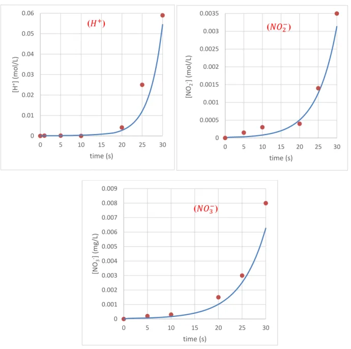
Figures II.6 and II.7 present the predicted and calculated concentrations of 𝐻+, 𝑁𝑂
2− and 𝑁𝑂3−ions
in water, by imposing short contact times versus the two GAD reactor configurations.
Figure II.6. Concentrations of 𝐻+, 𝑁𝑂2− and 𝑁𝑂3−ions in water in batch GAD reactor: ● predicted value,
▬ measured value 0 0.01 0.02 0.03 0.04 0.05 0.06 0 5 10 15 20 25 30 [H +] (mol/L) time (s) 0 0.0005 0.001 0.0015 0.002 0.0025 0.003 0.0035 0 5 10 15 20 25 30 [N O2 -] (m o l/L) time (s) 0 0.001 0.002 0.003 0.004 0.005 0.006 0.007 0.008 0.009 0 5 10 15 20 25 30 [N O3 -] (m g/L) time (s) (𝐻+) (𝑁𝑂2−) (𝑁𝑂3−)
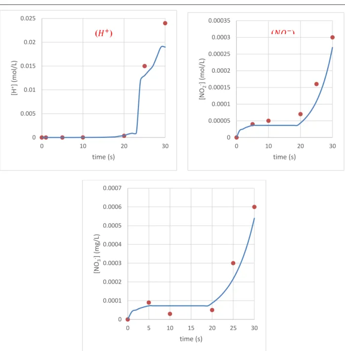
Figure II.7. Concentrations of 𝐻+, 𝑁𝑂2− and 𝑁𝑂3−ions in water in plate GAD reactor: ● predicted value,
▬ measured value.
Whatever the configuration of the GAD reactor, the concentrations of predicted and measured plasma species are in agreement. Several attempts at adjustments have made it possible to find this compromise between experience and mathematical model by advancing the appropriate kinetic equations. Tiny amounts of nitrite, nitrate and protons get into the water. The question that must be asked, does this material have an impact on the reaction with a reactive target? is that we will try to find out in the next section.
0 0.005 0.01 0.015 0.02 0.025 0 10 20 30 [H +] (mol/L) time (s) 0 0.00005 0.0001 0.00015 0.0002 0.00025 0.0003 0.00035 0 10 20 30 [N O2 -] (m o l/L) time (s) 0 0.0001 0.0002 0.0003 0.0004 0.0005 0.0006 0.0007 0 5 10 15 20 25 30 [N O3 -] (m g/L) time (s) (𝐻+) (𝑁𝑂 2−)
II.4.2 Plasma reaction with phenol
Once the kinetic model has been validated on distilled water, it can be tested on a reactive target. Phenol was chosen for the physicochemical characteristics it possesses in an aqueous medium as well as for the numerous applications which it undergoes in the presence of plasma-GAD.
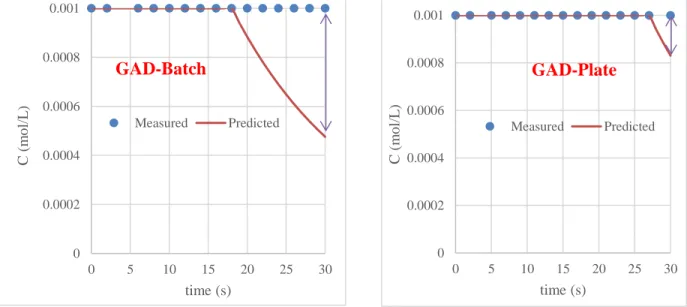
Figures II.8 and II.9 present the predicted and calculated concentrations of phenol aqueous solution (10-3 mol L-1), by imposing short contact times by using the two GAD reactor configurations.
Figure II.8. Phenol removal in water by plasma GAD reactors
In the presence of phenol, there is a difference between the values measured and those predicted by the model. An adjustment with a convincing kinetic scenario is valid up to 18 s for the GAD-Batch and 27 s for the GAD-plate. This is explained by the high convection in the first case which
accelerates the active species by transporting them more easily under the reaction bulk. The differences are explained by the existence of an electric field generating the acceleration of
light species (electrons), which by their velocities transfer their kinetic energy to the phenol molecule which will be in the excited state: sensitization phenomena.
0 0.0002 0.0004 0.0006 0.0008 0.001 0 5 10 15 20 25 30 C ( m o l/L ) time (s) Measured Predicted 0 0.0002 0.0004 0.0006 0.0008 0.001 0 5 10 15 20 25 30 C ( m o l/L ) time (s) Measured Predicted GAD-Batch GAD-Plate
.
References:
[1] M. Capocelli, E. Joyce, A. Lancia, T.J. Mason, D. Musmarra, M. Prisciandaro, Sonochemical degradation of estradiols: incidence of ultrasonic frequency, Chem. Eng. J. 210 (2012) 9–17 [2] F. Abdelmalek, S. Gharbi, B. Benstaali, A. Addou, J.-L. Brisset, Plasmachemical degradation of azo dyes by humid air plasma: Yellow Supranol 4 GL, Scarlet Red Nylosan F3 GL and industrial waste, Water Res. 38 (2004) 2339–2347.
[3] F. Abdelmalek, R.A. Torres, E. Combet, C. Petrier, C. Pulgarin, A. Addou, Gliding Arc Discharge (GAD) assisted catalytic degradation of bisphenol A in solution with ferrous ions, Sep. Purif. Technol. 63 (2008) 30–37.
[4] C. Ayrault, J. Barrault, N. Blin-Simiand, F. Jorand, S. Pasquiers, A. Rousseau, J.M. Tatibouët, Oxidation of 2-heptanone in air by a DBD-type plasma generated within a honeycomb monolith supported Pt-based catalyst, Catal. Today 89 (2004) 75–81.
[5] J. Xue, L. Chen, H. Wang, Degradation mechanism of Alizarin Red in hybrid gas–liquid phase dielectric barrier discharge plasmas: Experimental and theoretical examination, Chem. Eng. J. 138 (2008) 120–127
[6] M.R. Ghezzar, F. Abdelmalek, M. Belhadj, N. Benderdouche, A. Addou, Gliding arc plasma assisted photocatalytic degradation of anthraquinonic acid green 25 in solution with TiO2, Appl. Catal. B: Environ. 72 (2007) 304–313.
[7] M.R. Ghezzar, S. Ognier, S. Cavadias, F. Abdelmalek, A. Addou, DBDplateTiO2 treatment of Yellow Tartrazine azo dye solution in falling film, Sep. Purif. Technol. 104 (2013), 250-25 [8] N. Saïm, M.R. Ghezzar, C. Guyon, F. Abdelmalek, M. Tatoulian, A. Addou, New prototype for the treatment of falling film liquid effluents by gliding arc discharge part II: Plasmacatalytic activity of TiO2 thin film deposited by magnetron sputterin, Chem. Eng. Process. Process Intensif. 98 (2015) 32–40.
[9] H. Hentit, M.R. Ghezzar, M. Womes, J.C. Jumas, A. Addou, M.S. Ouali, Plasmacatalytic degradation of anthraquinonic acid green 25 in solution by gliding arc discharge plasma in the
presence of tin containing aluminophosphate molecular sieves, J. Mol. Catal. A: Chem. 390 (2014) 37–44.
[10] N. Haddou, M.R. Ghezzar, F. Abdelmalek, S. Ognier, M. Martel, A. Addou, Plasmacatalytic removal of lead acetate assisted by precipitation, Chemosphere 107 (2014) 304–310.
[11] D. Shao, J. Hu, C. Chen, G. Sheng, X. Ren, X. Wang, Polyaniline Multiwalled Carbon Nanotube Magnetic Composite Prepared by Plasma-Induced Graft Technique and Its Application for Removal of Aniline and Phenol, J. Phys. Chem. C 114 (2010) 21524–21530.
[12] Q. Wang, X. Wang, Z. Chai, W. Hu, Low-temperature plasma synthesis of carbon nanotubes and graphene based materials and their fuel cell applications, Chem. Soc. Rev. 42 (2013) 8821– 8834.
Three plasma processing modes are used in plasmachemistry according to the order of magnitude of the reaction time: (i) conventional: hours, (ii) temporal post-discharge: discharge of a few seconds or minutes followed by a post-reaction of several hours or days and (iii) sensitization: a few seconds are enough to make a given molecule to be more reactive.
The latter case has been investigated in this work. Modeling-simulations and experiments were used to study the sensitization phenomena in the presence of a plasma discharge generated by Gliding Arc Discharge in aqueous medium.
The penetration theory was used to predict the concentration values of nitrous species and protons in water. The validation was carried out successfully by repeatable experiences. The same model was applied in the presence of phenol to examine the time which is able to make this molecule abler to react with plasma-species or other molecules. With the comparison between measured and predicted outputs of phenol concentrations, the two configurations of GAD reactor show some divergence between model and experiments in the interval of [1, 18 s] and [1, 27 s] for GAD-Batch and GAD-Plate reactors, respectively. These times are the range of sensitization phenomena in the plasma treatment by Gliding Arc discharge.
In the future, we project to calculate the electrical field able to increase the energy state of the molecule when it is treated for few seconds by plasma-GAD.
![Tabel I.1: plasma speices .[58]](https://thumb-eu.123doks.com/thumbv2/123doknet/13332325.401056/23.892.199.628.102.374/tabel-i-plasma-speices.webp)