Publisher’s version / Version de l'éditeur:
Vous avez des questions? Nous pouvons vous aider. Pour communiquer directement avec un auteur, consultez la
première page de la revue dans laquelle son article a été publié afin de trouver ses coordonnées. Si vous n’arrivez pas à les repérer, communiquez avec nous à [email protected].
Questions? Contact the NRC Publications Archive team at
[email protected]. If you wish to email the authors directly, please see the first page of the publication for their contact information.
https://publications-cnrc.canada.ca/fra/droits
L’accès à ce site Web et l’utilisation de son contenu sont assujettis aux conditions présentées dans le site
LISEZ CES CONDITIONS ATTENTIVEMENT AVANT D’UTILISER CE SITE WEB.
Internal Report (National Research Council of Canada. Division of Building Research), 1975-09-01
READ THESE TERMS AND CONDITIONS CAREFULLY BEFORE USING THIS WEBSITE. https://nrc-publications.canada.ca/eng/copyright
NRC Publications Archive Record / Notice des Archives des publications du CNRC : https://nrc-publications.canada.ca/eng/view/object/?id=c7ce19ac-20f2-4622-8371-e2ebecb86981 https://publications-cnrc.canada.ca/fra/voir/objet/?id=c7ce19ac-20f2-4622-8371-e2ebecb86981
Archives des publications du CNRC
For the publisher’s version, please access the DOI link below./ Pour consulter la version de l’éditeur, utilisez le lien DOI ci-dessous.
https://doi.org/10.4224/20358704
Access and use of this website and the material on it are subject to the Terms and Conditions set forth at
School roof survey in Saskatoon
NATIONAL RESEARCH COUNCIL OF CANADA DIVISION OF BUILDING RESEARCH
SCHOOL ROOF SURVEY IN SASKATOON
by
C.P. Hedlin, D.G. Cole and J.T. Makohon
Internal Report No. 419 of the
Division of Building Research
OTTAWA September 1975
The high incidence of failure in flat roofing has led to an increased effort to identify the factors that produce the
problems and to find solutions for them. This requires both
laboratory and field research on a variety of questions concerning properties and performance of roofing materials. It is necessary to know about the conditions under which the roofing materials work if one is to explain their behavior. It was for this reason that a field study involving on-site observation of roof construction, with step-by-step documen-tation of the construction procedures, was carried out.
Ottawa
September 1975
C.B. Crawford Director, DBR/NRC
SCHOOL ROOF SURVEY IN SASKATOON by
C.P. Hedlin, D.G. Cole and J.T. Makohon
In 1972 the Roofing Research Program at the Prairie Regional Station of the Division of Building Research in Saskatoon was extended to include a study of roofs of a number of school
buildings. With the agreement of the Saskatoon School Boards a
long-term study was initiated that included on-site documentation of details during construction, to be followed by periodic
inspection to determine subsequent roof performance. The Boards,
in turn, obtained the agreement of the contractors and sub-contractors involved in the construction of several new
facilities at seven existing schools: St. Charles', E.D. Feehan,
St. Mary's, Vincent Massey, St. Matthew's, Prince Philip and Wilson.
A brief record of visual and photographic observations and
measurements for five of these schools is reported. Periodic
inspections will involve certain other measurements. It is hoped
that a nuclear moisture meter can be obtained to permit assessment of moisture content changes in the systems.
Roofing inspectors employ check lists in their work, and although the present survey is of a different type, the
observations reported were based on such a list. It is
anticipated that this study will result in some changes and
additions to it. The use of a valid list of this type would
permit future surveys to be briefer and more systematic in terms of labour input.
The opportunity to observe on-site construction procedures has been extremely useful, although results that can be
correlated with performance in a meaningful way are difficult to
secure. More data on materials (insulation and felt moisture
content, bitumen temperatures at the time of application, bitumen viscosity, etc.) would be desirable; unfortunately, some
measure-ments required equipment that was unavailable at the time. Other
information was missed because it is impractical to remain on
site at all times. It may be possible in the future to obtain
information by setting up special equipment to permit particular measurements to be made during the construction process.
E.D. FEEHAN SCHOOL
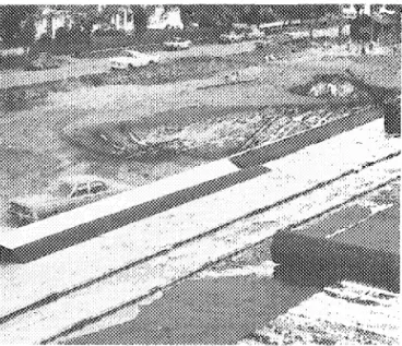
Two one-storey areas were added to the original school, one at the south end of the main building, the other at the north end (Figure 1).
Construction Schedule
Walls largely completed by 10 May, steel roof joists placed
18 May, steel deck placed 13 June, roofing in process on Area II
by 3 July, held up by strike but nearing completion 19 July, roofing on Area I nearing completion 31 July.
Walls
Cavity walls are of concrete block on inner wythe, with liquid-applied vapour barrier on outer surface of inner wythe, 2-in. rigid glass fibre insulation placed outside of 3-in. cavity, exterior wythe of brick or concrete block (Figure 2a). Roof
Structural:
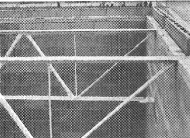
Area I - Steel joists run N-S, span 68 ft, rest on both wythes of wall, are bolted to secure at S wall (Figure 2b), welded at N wall, reverse cambered to drain water to middle of roof; ends of joists constitute frame for upper part of S wall; there are three lines of cross bracing for joists.
Area II - Steel joists run E-W, span 70 ft 4 in.,
reverse cambered, at Wend rest on wall or I beam spanning opening, at E end rest on post and I beam, further distance of 7 ft 4 in. to existing building spanned by another set of joists, end of joists constitute framing for upper part of W wall
(Figure 2C). Deck:
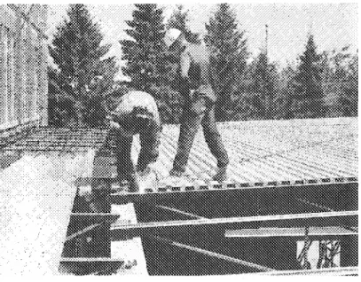
Area I - Steel, 50 per cent acoustical, flutes E-W, 24 in. sheets, overhang outside of W wall.
Area II - Steel, flutes E-W, 40-in. by 22-ft sheets,
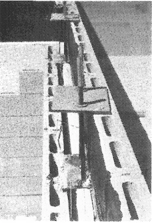
20-gauge on 3 north bays (approximately 22 ft) and for 10 ft along E side, remainder 22-gauge, secured to angle iron welded to joists attached to the existing building on E wall, about l6-in. parapet on N wall, overhangs S wall (Figure 2d).
-3-Cant and Blocking:
Area I - 3 in. high by 4 in. wood cant on 2-in. (nominal) blocking round perimeter.
Area II - 6 in. high by IS in. plywood cant (Figure 2e). Vapour Barrier:
Area II - Two-ply perforated, asphalt-impregnated felt run across flutes to top of cant, no fold-back over insulation
(Figure 2f)
Insulation Storage (Outside of blocking) :
Area II - l-1/8-in. bead type polystyrene mopped to vapour barrier, S/8-in. wood fibreboard mopped then flipped
over to adhere to polystyrene; insulation covers cant (Figure 2£1. Membrane:
Area II - Four-ply, IS-pound, asphalt-impregnated, perforated organic felt, laid 2 and 2.
Bitumen:
Type 1, all transport by bucket, spread by hand mopping.
ST. MARY'S SCHOOL
This construction houses a gymnasium and rises about two storeys above ground level (see Figures 3 and 4a).
Construction Schedule
Steel roof joists placed 5 May, steel deck placed 26 May, roofing started 30 May (crew of six), completed, including gravelling, 1 June.
Walls
An 8-in. vermiculite, filled concrete block up to roof level, one tier of 4-in. blocks used to cover the ends of the roof
joists (Figure 4b) Roof
A roof-wall intersection for the S wall is shown in Figure S.
Structural:
Steel joists span 42 ft, 6 ft OC, are cross-braced. Deck:
Steel, 100 per cent acoustical, 24-in. sheets, flute valleys 2-1/2 in. wide, lands 3-1/2 in. wide, depth 1-1/2 in., two-point welding to each joist, welds aluminum painted, joints crimped every 18 in., flutes E-W, deck butts tight against 4-in. concrete block at E and Wwalls (Figure 4c), acoustic deck flutes filled with glass fibre batting.
Cant and Blocking:
2 by 4 blocking abuts 4-in. concrete block, two 2-in. wood members overlie the blocking, the top one wide enough to cover the 4-in. concrete block, the two top members cut to provide a 3-1/2 by 3-l/2-in. cant (Figure 4d).
Vapour Barrier: None.
p
-5-Insulation:
2 by 4 ft by 1-1/8 in. extruded polystyrene, sprinkle mopped to deck, long dimension running parallel to deck flutes,
joints staggered, no taping (Figure 4e). Membrane:
Four plies of asphalt-impregnated organic felt, laid
2 and 2, run parallel to flutes. To start laying membrane,
1/2 width of first strip of felt folded back, mopped, then flipped over and bonded to insulation; process repeated for second half (Figure 4f), subsequent plies bonded with full mopping.
Stripping:
Two plies, first one to top of cant slope, second one over nailer and secured on outside flush with exterior wall surface, top surface mopped to top of cant only.
Bitumen:
Type 1 asphalt, hand mopped for interply bonds, spreader for flood coat.
Gravel:
Applied with spreader in pour coat. Counter Flashing:
On exterior walls, 8-ft lengths of sheet metal having S-lock joints, end tabs nailed on top of nailer strip and on cant slope (Figure 4g), corners caulked; along existing building set in reglet and caulked there with PRC 7000 polysulphide
polymer (Figure 4h). Roof Penetrations:
One drain and three mechanical equipment curbs (Figure 4i).
Slopes:
ST. MATTHEW'S SCHOOL
The addition consists of a two-storey gymnasium (Area I) and
a number of rooms and hallways of one-storey height (Area II)
(Figures 7, Ba). Construction Schedule
Building begun about the end of April, foundation placed by 11 May, floor placed approximately the last week in May, walls constructed approximately the last two weeks in June, roof joists and deck in place by the last week in June, cant strip placed at the end of June, roofing completed during third and fourth weeks in July.
Walls
Cavity walls constructed of concrete block (inner wythe 4-or B-in. block, outer wythe 4-in. block), a brush-applied vapour barrier placed on the exterior surface of the inner wythe, a 3-in. cavity, 2-in. bead type polystyrene secured between wire ties, insulation application nearing wall construction ended below top wire tie, final wall insulation placed just prior to placing blocking and cant strip (this insulation covers the ends of the steel deck) (Figure Bb).
Roof
Structural:
Area I - Open web steel joists, span 39 ft,
approximately 6 ft 3 in. OC.
Area II - Steel joists of varying spans.
Joists rest on steel base plates secured to walls
-base plates of two types: (1) 6 by B in. with two SIB-in. pins
set in concrete poured into block cores, (2) double set of
plates both spanning wall cavity, lower plate set two or three blocks down and top one, supporting joist, secured to it by pair of bolts (Figure Bb).
Where Areas I and II abut, joists supported by outer
-7-Deck:
Area I - Steel, 100 per cent acoustic, 24-in. wide sheets welded to each joist at two points, flutes running N-S, secured at Nand S walls to 1/4- by 3-in. steel plate secured, in turn, to top of wall (Figure 8c), deck ends flush with outer
surface of inner wythe on Nand S walls. Along E and Wwalls
abuts two 2 by 6 planking laid on edge, rests on block wall, covers ends of joists, flush with deck at top, deck sawed to fit and stiffened with approximately 20-gauge sheet metal along cut edge (Figure 8d).
Area II - Steel, non-acoustic, 40-in. sheets welded at three points, terminating flush with outer surface of inner wythe, abuts insulation of exterior walls (Figure 8e), abuts wall of original building with little gap.
Cant and Blocking:
Area I - 2 by 4 or 2 by 6 blocking laid flat and secured to deck by nailing, 3 by 3 in. wood fibre board cant nailed to blocking, abuts parapet rising about 7 in. above deck surface (Figure 8f).
Area II similar to Area I. Vapour Barrier:
Area I - セッュュ・イ」ゥ。ャL impermeable asphalt-paper, running
across flutes.
Insulation Storage (Outdoors on blocking):
1-1/8 in. rigid glass fibre, long dimension across flutes.
Membrane:
Four plies of lS-lb perforated, asphalt-impregnated organic felts, all sheets running across flute direction, starting on N side, 1/2 sheet run to top of parapet, followed by full sheet, repeated for 2 and 2 application.
Stripping:
Four plies, 1/4 roll, 1/3 roll, and 1/3 roll brought to top of 2 by 4 nailer secured to top of parapet, fourth ply of 1/2 roll width extending over nailer and nailed on outside
Vapour barrier, insulation, membrane, and stripping similar to that of Area I; at abutment to Area I, regletted counter flashing used (Figure 8h).
Bitumen:
Type 1 asphalt, spreader or mop applied. Gravel:
In pour coat. Roof Penetrations:
Drains set by using three or four plies of glass fabric and mastic placed round drain opening, drain cover clamped
-9-PRINCE PHILIP SCHOOL
Construction in three different areas:
Area I Open area classroom, octagonal in shape,
Area II - Classrooms, washrooms and halls,
Area III - Gymnasium (Figure 9). Construction Schedule
Construction begun end of April, masonry walls completed about 18 May, deck placed on Area III 24 May, completed on other areas by about 3 August, roofing begun 16 August, completed about 24 August.
Walls
Much of it single wythe concrete block. Roof
Structural:
Area I - Eight glue-laminated beams radially spaced, each spanning approximately 36 ft from outer wall to centre of area, no centre support (perimeter rods in tension) (Figure lOa).
Area II - Wood beams, some glue laminated (Figure lOb). Area III - Precast double tees span 60 ft, 8 ft wide, 29 in. deep, butt joints secured together by welding previously installed rods, positive camber, welded to steel plates set in concrete in U blocks (Figure IDe).
Deck:
Area I Area II Area III
- I-SIS-in. spruce.
- Plywood or I-SIS-in. spruce (Figure 10d). - Pre-cast double tees grouted at joints and
sanded to smooth (Figure IDe), plywood over l4-ft extension at Wend of Area III.
Cant and Blocking:
Area I - 1 by 4 overlaid by 2 by 4 placed round perimeter for blocking, no cant.
Area II - 2 by 6 overlaid by 1 by 6 for blocking, 2 by 2 cant.
Area III - 2 by 6 blocking overlaid by 4 by 4 cant abuts framing members of mansard type roof (Figures 10f, 109).
Vapour Barrier:
Area I - Commercial asphalt paper stapled to deck, enough left to fold back on top of insulation (Figure 10h).
Area III - Asphalt primer on concrete, then perforated asphalt-impregnated felt.
Insulation Storage (inside Area III):
Area I - 1-1/2 in. thick rigid glass fibre mopped to vapour barrier, electrical conduit lying on top of deck and insulation slotted to provide inset for it (Figure 10i); I-in. layer of rigid glass fibre insulation mopped on first layer; Areas II and III same as Area I.
Membrane:
Areas I and II - Four plies of IS-lb perforated, asphalt-impregnated felt, laid 2 and 2 running NE - SW
(Figure 10j).
Area III - Four plies of same felt run N-S. Gravel:
Spread in pour coat. Roof Penetrations:
Drains, Area I - Water runs to gutter around perimeter, then to Area II (Figure 10k).
Area II - Two drains, mastic sealed when bolted down on top of four-ply membrane.
Area III - One drain midway along S wall, internal drain.
Counter Flashing:
Area I - Metal under shingled cupola wall at top of slope.
po
-11-WILSON SCHOOL
Because of differences in construction, this addition is divided into three different areas (Figure 11).
Construction Schedule
Interior wythe of all walls completed before 10 May, steel joists on Area I placed 2 May, steel roof deck laid 24 May, blocking and cant strip placed 26 May, roofing begun on Area I 29 May, completed about 2 June, nearly completed on all areas by 5 June, counterflashing finished before 14 June.
Walls
Cavity walls of concrete block interior wythe with liquid-applied vapour barrier on exterior surface, a 3-in. cavity, 2 in. rigid glass fibre insulation placed against the exterior surface of the interior wythe during construction of the walls, a brick exterior wythe secured by wire wythe ties (Figure l2a).
Roof
Roof-wall intersection along W wall of Area I shown in
Figure 13.
Structural:
Steel joists over Area I span 58 ft and are
approximately 6 ft 2 in. OC, slope is N-S at approximately
0.4 in. in 12 in., peaking at the middle of the area; Area II
(Figure l2b) has steel joists spanning 19 ft 6 in., 7 ft OC; on
Area III, steel joists span 12 ft, 4 ft 6 in. OC.
On exterior walls, ends of joists secured by bolting
or welding to steel base plates set in concrete in U blocks;
where roofs abut higher walls joists are supported by angle iron secured to wall or are let into wall (Figure l2c).
Deck:
Area I - Steel, 50 per cent acoustic (Figure l2d), 24 in. wide, welded to each joist at two points, flutes run E-W, at E and Wwalls welded to angle iron set into concrete in U blocks, slopes as in Figure 14, sharp change in slope 7 ft from Nand S ends of Area I (Figure l2e).
Area II - Steel, 40 in. wide, three-point welding to each joist, flutes N-S, terminate approximately even with outer surface of inner wythe at S wall.
Area III - Steel, 40 in. wide, three-point welding to each joist, flutes N-S, terminate approximately even with outer surface of inner wythe at S wall.
Cant and Blocking:
Area I - 2 by 6 blocking secured to deck by screws,
3 by 6 cant nailed to blocking, overlying brick wythe (Figure l2f). Area II - Similar to Area I, blocking and cant run
along existing building. Area III - Similar. Vapour Barrier:
Area I - Two plies of perforated, asphalt-impregnated organic felt on bays 1 and 15, 1 ply elsewhere with a 2-in. lap, sprinkle mopped to deck, acoustic portions of deck filled with flass fibre batting (Figure l2g).
Area II - Similar double vapour barrier on area adjacent to bay 1 of Area I.
Vapour barrier running across deck flutes; first strip of vapour barrier 1/2 roll wide, wythes running along E and W walls and a sufficient flap left to fold about 9 in. over the top of the insulation; similar fold-over prevails along Nand SwaIls
(Figure l2g).
Insulation Storage (Outside on Blocking):
Areas I and II - Two layers of 3 by 4 ft by 3/4 in. thick rigid glass fibre, joints staggered, not taped, full mopping to vapour barrier and between layers of insulation
(Figure l2h), sealed off for night, seal cut next morning. Membrane:
Areas I and II - Four plies of l5-lb perforated, asphalt-impregnated organic felt placed in most cases 2 and 2, terminated at top of cant (Figure l2i).
Stripping:
Two layers, one to top of cant, the second over and nailed outside of cant.
-13-Bitumen:
Type I asphalt pumped from kettle to roof, application by mopping on steep slopes, spreader elsewhere; estimated
temperature 375 of.
Gravel:
Embedded in the pour coat on all areas. Roof Penetrations: Figure 11. Slopes: Figure 14. Counter Flashing: Figure l2j.
ACKNOWLEDGEMENTS
The authors wish to express appreciation to the Saskatoon School Boards, particularly to T. Conn and B. Kroeker; to the contractors, foremen and individual workmen who assisted in many
ways. It is hoped that they were not inconvenienced and that
70'- 4" 7' - 3" + o + o o c + ROOF DRAIN o STACK o VENTILATOR ().. PHOTO ".UMBER FIGURE 1
CONSTRUCTION AND SURVEY DETAILS ON PLAN VIEW
e
I o o o 0 + '@ 0 ST. 100% AC. f--26' -10" -r<'l V + ROOF DRAIN o STACK o CURB 0- PHOTO NUMBER - STEEL DECK£
SPAN 6' JOISTS O. C. FIGURE 3CONSTRUCTION AND SURVEY DETAILS ON PLAN VIEW
OF ROOF OF ST. MARY'S SCHOOL
(c) Cd)
(e)
(h)
(g)
(i)
4 PLIES (LAID 2 and 2)
INSULATION - 1 iOセG EXTRUDED POLYSTYRENE
STEEL DECK - 22 GAUGE OPEN WEB STEEL JOIST
15- LB PERF ASPHALT FELT
STRIPPING - 2 PLIES S LOCK GALV ___ SHE E T ME TA L ---
NエM]WGセゥセセセセセセセセセセセセセ
COUNTER FLASHING '/ 2" 6" CANT 2": 4" BLOCKING 2".4" CONCRETE BLOCK + -FIGURE 5SECTION VIEW OF ROOF-WALL INTERSECTION - SOUTH WALL
OF ST. MARY'S SCHOOL
VERTICAL SCALE (INCHES) o 2
o
HORIZONTAL SCALE ( FEET) FIGURE 6ORTHOGRAPHIC PROJECTION OF ROOF SURFACE OF ST. MARY I S SCHOOL
EXISTING BLDG
セセセ
+ ROOF DRAINo
STACKo
VENTILATOR®-
PHOTO NUMBER:/:!i?
-
STEEL DECK :::}.::::. 39' SPAN • • • • 0 ,. . . - . . . . ᄋZᄋZᄋZᄋZセZゥ 6'-3" JOISTS 0 C...
GiヲAセA
C§r
.:.:II
'. セ.'
-:セ
.:..:.-{1)
T セセ
セセ
:.':':.;.:. :ZZZZセZZNセ
®..
0 0 セZNセ:::::::::::..::.: DゥHセヲ
(§)
+ I - - - セNZNZNZNZNZ'@®
u:;nr
<s:セiセ
(/) 0 0-I
39I..
6
1-
3
11CD-o
20 40 FEET FIGURE 7CONSTRUCTION AND SURVEY DETAILS ON PLAN VIEW OF
(a)
(c)
(b)
Cd)
(g)
(1)
Figure 8, St. Matthew's School (cont'd)
`MMZセ]]]]]]]]ZZZZZZZZZMMML - - - -セM ill
---ff
rtf
[iJ +-
---ooo----m--60 FEET 20 40o
- - - - + - - 0-+-o
jD
[gJ + ROOF DRAIN o STACKo
VENTILATOR • BENCH MARK - - - SURVEY LINEo
and NUMBER0-
PHOTO NUMBER FIGURE 9CONSTRUCTION AND SURVEY DETAILS ON PLAN
VIEW OF ROOFS OF PRINCE PHILIP SCHOOL
(a) (c) (e)
....-'
1::::::::::;-(;;:::::::::: (b) Cd) (f)(g) (i) (h) (j) Figure 10, (k)
1
III III 12' 4'-6" nom.3 ST. 1(2)ZID
o o +®-•
I o CJ) o + + nom.3 f - - - J . . . . - - - & - @ - - - ----!..-__L L 1 - - - 1 0 7 ' - - - _ +o
o
I (2) 12' ·4'-6"+
FALL 2" IN 12.nom. 3. NOMINAL 3" DROP TO DRAIN ST. STEEL DECK
50°/0 AC 50 °/0 ACOUSTICAL
0- PHOTO NUMBER
FIGURE 11
SURVEY AND CONSTRUCTION DETAILS ON PLAN VIEW
OF ROOF OF WILSON SCHOOL ADDITION
(a) (b)
(c) (d)
(e) (f)
(i)
Figure 12. Wilson School (cont'd)
(j) :::1 111 .:J III Zセセi :::1
WIRE WYTHE TIES セconcrete U BLOCK II III II CONCRETE BLOCK
VAPOUR BARRIER-BRUSH APPLIED TO CONCRETE BLOCK INSULATION - 2" RIGID GLASS FIBRE
AIR SPACE
BRICK EXTERIOR FINISH GRAVEL
ASPHALT FLOOD COAT
15 LB. PERF. ASPHALT ROOFING
MEMBRANE-4 PLIES (LAID 2 and 2)
INSULATION - 2 LAYERS 3/4" RIGID GLASS FIBER
セpour BARRIER -15 LB. PERF. ASPHALT FELT (I PLY)
STEEL DECK - 22 GAUGE OPEN WEB STEEL JOIST 15 LB. PERF. ASPHALT FELT
STRIPPING - 2 PLIES
S LOCK GALV. SHEET METALCOUNTER FLASHING セiBGMウセセ
セセゥセセ][セGセセセセGセQUセUUェ
セ3"I 6" CAN T ]・GAエイセiZイZZZイZZ]ZZjエゥAlMMcャZAlMャAZャZャl]]]ZAlNi]セZZ]セZZZZZZZZセ
2"16 " BLOCKING
FIGURE 13
ROOF-WALL INTERSECTION - SOUTH WALL OF WILSON SCHOOL
セ ..
\セZセ
"-//
HORIZONTAL SCALE (FEET) 2[ VERTICAL I SCALE (INCHES) o FIGURE 14ORTHOGRAPHIC PROJECTION OF ROOF SURFACE AREAS I