HAL Id: hal-01060304
https://hal.inria.fr/hal-01060304
Submitted on 3 Sep 2014
HAL is a multi-disciplinary open access
archive for the deposit and dissemination of
sci-entific research documents, whether they are
pub-lished or not. The documents may come from
teaching and research institutions in France or
abroad, or from public or private research centers.
L’archive ouverte pluridisciplinaire HAL, est
destinée au dépôt et à la diffusion de documents
scientifiques de niveau recherche, publiés ou non,
émanant des établissements d’enseignement et de
recherche français ou étrangers, des laboratoires
publics ou privés.
Intra-operative Registration for Deep Brain Stimulation
Procedures based on a Full Physics Head Model
Alexandre Bilger, Eric Bardinet, Sara Fernández-Vidal, Christian Duriez,
Pierre Jannin, Stéphane Cotin
To cite this version:
Alexandre Bilger, Eric Bardinet, Sara Fernández-Vidal, Christian Duriez, Pierre Jannin, et al..
Intra-operative Registration for Deep Brain Stimulation Procedures based on a Full Physics Head Model.
MICCAI 2014 Workshop on Deep Brain Stimulation Methodological Challenges - 2nd edition, Sep
2014, Boston, United States. �hal-01060304�
for Deep Brain Stimulation Procedures
based on a Full Physics Head Model
Alexandre Bilger1 , ´Eric Bardinet2 , Sara Fernandez-Vidal2 , Christian Duriez1 , Pierre Jannin3
, and St´ephane Cotin1
1
Inria Lille - Nord Europe Research Centre
2
Centre de Recherche de l’Institut du Cerveau et de la Moelle ´epiniere, UMR-S975, Paris; Inserm
3
Equipe Medicis, U1099 LTSI, Universit´e Rennes I
Abstract. Brain deformation is a factor of inaccuracy during stereo-tactic neurosurgeries. If this phenomenon is not considered in the pre-operative planning or intra-pre-operatively, it could lead to surgical com-plications, side effects or ineffectiveness. In this paper, we present a patient-specific method to update the pre-operative planning based on a physical simulation of the brain shift. A minimization process estimates parameters of the simulation in order to compute the brain tissue defor-mation matching the partial data taken from intra-operative modalities. The simulation is based on a patient-specific biomechanical model of the brain and the cerebro-spinal fluid. We validate the method on a patient with a post-operative MRI.
1
Introduction
Targeting structures in sterotactic neurosurgery requires a high precision for the location and definition of the target. For instance, in deep brain stimulation (DBS), one of the main targets to stimulate is a 3 millimeters thick structure, the subthalamic nucleus. However, a combination of deformation and motion of the brain, known as brain shift, can occur during the procedure, depending on the surgical technique and the patient’s brain anatomy and pathology. Because of this phenomenon, the target or other structures can be displaced, compared to the pre-operative location. Elias et al.[4] reported an anterior commissure shift up to 5.67 mm with a mean of 0.98 mm, and higher shift values for the frontal pole.
Because brain shift is a major source of errors when applying the planned strategy intra-operatively, several groups have studied the problem of brain shift compensation using a deformable model, instead of using a fully intensity-based method. Skrinjar et al. [7] presented a method to deform pre-operative data according to a partial intra-operative brain surface, captured by a stereo camera, while Chen et al. [2] and Audette et al.[1] used a laser range scanner. However the equipment is not standard and requires a large working space without occlusion,
2
which is not the case in DBS procedures. The work of Wittek et al. [9] is very similar to [7] but they used intra-operative MRI to guide the deformable model and took extra care on the complex model of the brain tissue deformation. However [7] and [9] do not model physically the brain shift phenomenon, because they include artificial forces by adding virtual springs or constraints between pre- and intra-operative control points. None of these methods accounts for the effects of gravity, interaction of cerbro-spinal fluid (CSF) and brain tissue and loss of CSF. On the contrary, Chen et al. [2] used a computational model which accounts for CSF loss and gravity. They pre-operatively built a statistical atlas of deformation to solve the inverse problem intra-operatively.
We propose a new method to take into account brain shift during a stereo-tactic neurosurgical procedure. Because brain shift amount depends on many causes, such as the operating protocol or the mechanical parameters of the brain tissue, this variability leads us to deal with patient-specific data. It relies on high resolution pre-operative MR image and intra-operative image (CT scan) of the patient’s brain, acquired once the brain has shifted, but the method could be extended to other modalities such as intra-operative MRI. The pre-operative data are deformed according to a physical model of brain shift, mainly based on a (CSF) interaction with the brain tissue, gravity and brain-skull interactions. The input parameters of the brain shift model are estimated intra-operatively with a measure of similarity between a series of pre-computed deformed configu-rations and the data from the intra-operative image. The deformed configuration that best fits the intra-operative data enables to compute the displacement and deformation of internal structures. With this information, the surgeon is able to update the pre-operative planning data (target coordinates, trajectory angles etc).
The following section describes the brain shift simulation and how we use it to solve the intra-operative registration based on a physical parameters estimation. Section 3 presents the results and the validation on a post-operative MR image of one patient. Section 4 concludes and addresses future steps for the method.
2
Materials & Methods
2.1 Data
Patient data consisted of pre-operative Gadolinium enhanced T1-weighted MRI acquired with a GER 1.5T scanner. Targeting of the basal ganglia follows a pipeline that is similar to the inclusion protocol described in [3]. In summary, pre-operative 1.5T T1-weighted MRI data from a DBS-eligible patient goes through the following steps: first the AC-PC coordinates are interactively defined; then, the scalp, gray/white matter, and sulci are segmented from the T1-weighted MRI; finally, spatial normalization of the patient data in the atlas space is per-formed.
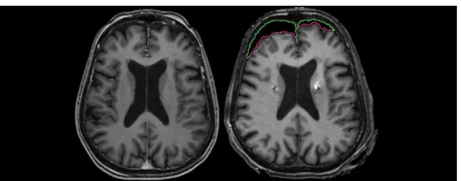
Fig. 1: Pre-operative (left) MR image without brain shift, and post-operative (right) MRI showing asymmetric brain shift. The green and pink contours is a segmentation of the pneumocephalus (air inside skull). The pink line represents the surface of the brain in contact with air.
2.2 Presentation of the model
The patient data are used in a brain shift simulation, relying on a physics-based model of the brain tissue deformation, the contact response with the skull and the falx cerebri, and the interaction with the CSF. All these simulation components are linked together with a mechanism to propagate forces and displacements to the other models. The deformation model imposes its displacements to the oth-ers, and forces created with these models (contact for instance) are propagated back to the deformation model. The different models used in our simulation for the brain hemispheres are: deformation, collision, buoyancy, mass and visual.
The brain deformation is computed using a non-linear geometric finite el-ement method, with a linear constitutive law. This allows for rotation in the model, while relying on a linear expression of the stress-strain relationship. De-tails of the computation method could be found in [5]. The viscous part of the brain behavior is omitted, because we focus on the static equilibrium after the brain has shifted. The equation relating the external forces f to node positions x can be written as f(x + dx) = f(x) + K(x)dx, with K the stiffness matrix depending on x. Both hemispheres are meshed independently with linear hex-ahedral elements for the FEM model. The forces produced by the mass model are computed on a volumic mesh made of linear tetrahedral elements, and prop-agated to the deformation model.
When the brain deforms, the simulation algorithm solves the contacts with the skull and the falx cerebri, considered as rigid. Unilateral interpenetration constraints are created when a collision is detected. The area near the brainsterm is assigned fixed Dirichlet boundary conditions to impose a null displacement constraint. The constraints are solved with Lagrangian multipliers. Figure 2 shows the boundary conditions and the different models.
The main cause of brain shift is a CSF loss [8]. The resulting force of the surrounding fluid acting on the brain tissue acts against the weight, so that the
4
Fig. 2: Schematic representation of the brain model and the set of constraints describing its interactions with the environment. The hexahedral FEM model for deformation is represented by the purple grid and the tetrahedral model for the mass by the pink triangles. In this pre-operative configuration, the patient is in the supine position (see the gravity vector direction g). The cerebro-spinal fluid surrounds the brain tissue and acts on it with pressure forces. The resultant force balances the weight (see the fCSF compared to the weight force mg). The brain
is under a null displacement constraint near the brainstem area. The illustration also shows the contacts between the brain and the skull.
brain is balanced. A CSF loss causes a fluid forces decrease, breaking the balance and leading to a brain shift. In order to cause a brain shift in our simulation, we include a model of CSF forces:
fCSF =
Z Z
S
ρ g h(P ) dS where ρ is the density of CSF (1000 kg/m3
), g is the norm of the gravity and h is the distance between a point P on the mesh and the fluid surface. The force fCSF is applied onto every immersed triangle S of the brain surface mesh.
Asymmetric brain shift is observed on post-operative images (see Fig. 1). To handle this property, two independent models of fluid forces are present in the simulation, each acting independently on each hemispheres. With this model, the deformation depends also on the patient’s head orientation compared to gravity direction, mechanical properties of the tissue and patient variability.
To recover the true rest configuration of the brain before applying gravity and external forces on the finite element model, we solve an inverse problem using an iterative geometric algorithm [6]. The algorithm is used with a static solver. The iterations are smoothed to handle the geometrical non-linearities of the deformation model.
Parameters to estimate As explained in section 2.2, the brain shift model depends on the following parameters: patient’s head orientation compared to gravity direction, patient variability (geometry), mechanical properties of the tissue and the amount of CSF lost during the procedure. The two first param-eters are known: we can measure the orientation of the patient’s head and the geometry is acquired by the segmentation of patient images. The mechanical parameters of the brain tissue have been estimated by several groups using dif-ferent techniques, but there is no consensus and there is no direct measurement technique personalized for a patient. Although it would be interesting to add the mechanical properties to the parameters to estimate, the deformation is also controlled by the CSF volume lost, meaning that these two parameters cannot be dissociated: the displacement of a material particle, as a function of the ma-terial properties and CSF volume lost, can have more than one fiber. We fix the mechanical properties to estimate a unique parameter type, the CSF volume lost. Moreover, the mechanical parameters are not the physical cause of the brain shift phenomenon. Finally, only the CSF volume lost is estimated. As we model both hemispheres independently, two quantities have to be estimated.
Error minimization In our algorithm, the only unknown input parameters are two volumes of CSF lost during the surgery. To estimate these parameters, we introduce a measure of similarity, to compare the final deformed geometry of the brain, obtained at equilibrium after applying a CSF loss in a simulation, and the visible surface of the brain, extracted from an intra-operative modality. The similarity between these two objects is defined with a least-squares approach:
d(S, M ) = X
xS∈S
kxS− p(xS, M )k 2
(1) with xS a point on the surface S of the intra-operative brain, p(xS, M ) is the
projection of the point xS on the surface M of the simulated brain. To compute
the projection of a point P on a triangular mesh, we first find the closest point of the surface. P is projected on every triangles around the closest point. We consider only the projections that are inside the corresponding triangle and take the one with minimal distance. If none of the projections are inside the corresponding triangle, we perform this same step on the edges around the closest point. If none of the projections are inside the corresponding edge, we consider the projection is the closest point. The measure is normalized by dividing by the number of points in S, and represents the average distance between both surfaces. The figure 3 shows a representation of such a projection in image space.
Our model is consistent with the correlation between the CSF loss and the amount of deformation, studied by [4]. The displacement norm of a point in the brain is an increasing function of the CSF volume lost. This property guarantees the convexity of the error as a function of the two CSF volume losses: a local minimum is a global minimum.
Even an efficient optimization method for our problem would require at least several tens of iterations to converge to an estimation of the parameters. Each
6
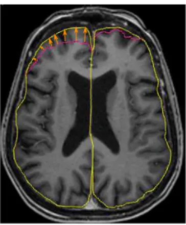
Fig. 3: Measure of similarity to be minimized: the triangular surface extracted intra-operatively, represented by a pink contour in this pre-operative axial MRI, is projected on the simulated brain surface (yellow contour). In this example, some points and their projection are depicted with an arrow. The measure is the average distance of projection.
iteration requires to compute a direct simulation, which takes time (more than 5 minutes) and therefore is not compatible with an application during a neurosur-gical procedure. To speed up the intra-operative computation, we pre-compute before the surgery a set of brain configurations, deformed by a simulated brain shift for a regular sampling of the parameters domain. Then, during the proce-dure, a mesh is extracted from an intra-operative image with a snake evolution based semi-automatic segmentation of the pneumocephalus, and compared to all the pre-computed deformed configurations. The configuration with the smallest error corresponds to the registered brain.
Finally, the displacement field enables to compute rapidly the displacement and deformation of other structures such as the ventricles, the target or the blood vessels. A summary of the whole process is available in the figure 4.
3
Results
In this section, we compare the result of our registration method to the pre-operative configuration, through a comparison of the blood vessels network. However, the quality of an intra-operative image does not allow to extract a ground truth. To get around this issue, we consider using a post-operative im-age instead. In the days following the procedure, intracranial air is replaced by the CSF produced and brain tissue shift back to its original configuration. We can consider the displacement has not yet started just after the operation. For this reason, for the validation of our method, we chose to use a post-operative MR image of the patient, where we can segment the structures of interest and compare them with the registered structures. We assume the intra-operative
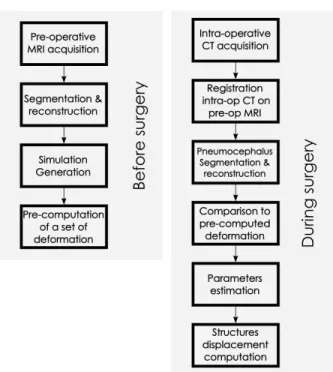
Fig. 4: Steps of our method (read from left to right, then from top to bottom): the acquired pre-operative MRI enables to generate a simulation. A set of deforma-tion is pre-computed. During the surgery, the pneumocephalus is extracted from the intra-operative CT, registered to the pre-operative data and compared to the set of pre-computed deformation. Finally, the displacement of the structures of interest is deduced. Among these steps, the most time consuming processes are done before the surgery.
configuration to register and the post-operative configuration of the brain are equivalent. With this assumption, in this section, the intra-operative data of our method are taken from the post-operative image: we only extract air from the image, in the same way as in the intra-operative image. Our method, presented to be applied on CT scans, does not differ with an MRI because air appears as a volume with no intensity in both imaging modalities CT and MRI. In both cases, the pneumocephalus is segmented semi-automatically with an active con-tour model. Other details from the post-operative image, and not visible in the intra-operative image, are not taken into account in the registration process. However, some structures of interest are segmented in the post-operative image for a comparison purpose (not used during the registration process): the post-operative data follow the same preprocessing pipeline that the prepost-operative one and is registered on the pre-operative space by a rigid method (FLIRT 6 DoF). The pre-operative segmented patient brain is used to generate several mod-els for the simulation: the mechanical model is made of 7538 linear hexahedral
8
elements, the model used for mass with 14671 linear tetrahedral elements, the collision model with 2940 triangles, and the model for buoyancy with 2772 tri-angles. In this study, the Young’s modulus E is set to 6 kPa and Poisson’s ratio to 0.45.
To estimate the CSF volumes parameters, a set of 169 brain configurations is pre-computed, with parameters varying from 0 cm3
to 24 cm3
. A higher number of configurations would result in more precision, but given the computation time, 169 configurations (on a laptop i7-4800MQ CPU) is a maximum for a global time compatible with a clinical use. We believe we can increase this number by optimizing our method. The different configurations are then compared to the intra-operative data, i.e. the brain surface in contact with intracranial air. A score of similarity is computed for each configuration according to the measure described in section 2.3. The minimum score corresponds to the parameters to estimate. The corresponding configuration is a registration of the whole brain. The comparison process on the complete set is almost instantaneous and does not requires any optimization.
The patient used for the validation of the method presents an asymmetric brain shift (See Fig. 1). We notice the right hemisphere has shifted more than the left. This phenomenon is found in the estimated parameters: we estimated that the right hemisphere needed a CSF loss of 18 cm3
to deform and match the intra-operative data, whereas the left hemisphere needed 12 cm3
. The average distance computed with these parameters is 2.5 mm for the right hemisphere and 1.8 mm for the left. The following results are based on these estimated parameters.
The displacement field and the shape functions of the FEM model is used to compute the displacement and deformation of internal brain structures. Most of the blood vessels are located in the sulci and if a blood vessel shifts on the trajectory of a stimulating electrode during a DBS procedure, it could lead to an hemorrhage. For this reason, we focus the tests of our method on the sulci.
To compare the different configurations, we use the following measure: d(X, Y ) = max 1 |X| X x∈X inf y∈Yd(x, y), 1 |Y | X y∈Y inf x∈Xd(x, y)
for two meshes X and Y and d the euclidean distance between two vertices. A smaller distance indicates more similarity. The distance between sulci in pre-operative configuration and post-pre-operative configuration is 2.7 mm. The distance between sulci in the registered configuration and post-operative configuration is 1.3 mm. We conclude our registration method gives a better estimation of the sulci location than using the pre-operative data.
4
Conclusion
In this paper, we presented a method to register the pre-operative configuration of the brain onto the intra-operative state. The registration is entirely based
on physics and handle patient-specific geometry, patient’s head orientation and asymmetry in the deformation. The algorithm provides also the physical dis-placement and deformation of other structures such as the blood vessels or the target. We showed on one patient with an asymmetric brain shift that our method is more efficient that simply assuming the pre-operative location : we compared the registered sulci with their post-operative location.
The method is independent from the constitutive law of the brain, and could be improved using a more accurate law. We believe the method precision will strongly depend on the accuracy of the geometries and the models. The next step of this work is to strengthen the validation on a larger series of patients and perform tests on the basal ganglia.
Acknowledgment
The authors would like to thank the French Research Agency (ANR) for funding this study through the ACouStiC project.
References
1. Audette, M.a., Siddiqi, K., Ferrie, F.P., Peters, T.M.: An integrated range-sensing, segmentation and registration framework for the characterization of intra-surgical brain deformations in image-guided surgery. Computer Vision and Image Under-standing 89(2-3), 226–251 (Feb 2003)
2. Chen, I., Coffey, A.M., Ding, S., Dumpuri, P., Dawant, B.M., Thompson, R.C., Miga, M.I.: Intraoperative brain shift compensation: accounting for dural septa. IEEE transactions on bio-medical engineering 58(3), 499–508 (Mar 2011)
3. D’Albis, T., Haegelen, C., Essert, C., Fern´andez-Vidal, S., Lalys, F., Jannin, P.: PyDBS : An automated image-processing workflow for planning and postoperative assessment of deep brain stimulation. International Journal of Computer Assisted Radiology and Surgery (2014)
4. Elias, W.J., Fu, K.M., Frysinger, R.C.: Cortical and subcortical brain shift during stereotactic procedures. Journal of neurosurgery 107(5), 983–8 (Nov 2007)
5. Felippa, C., Haugen, B.: A unified formulation of small-strain corotational finite elements: I. Theory. Computer Methods in Applied Mechanics and Engineering 194(21-24), 2285–2335 (Jun 2005)
6. Sellier, M.: An iterative method for the inverse elasto-static problem. Journal of Fluids and Structures 27(8), 1461–1470 (Nov 2011)
7. Skrinjar, O., Nabavi, A., Duncan, J.: Model-driven brain shift compensation. Med-ical image analysis 6(4), 361–73 (Dec 2002)
8. Slotty, P.J., Kamp, M.a., Wille, C., Kinfe, T.M., Steiger, H.J., Vesper, J.: The impact of brain shift in deep brain stimulation surgery: observation and obviation. Acta neurochirurgica (Aug 2012)
9. Wittek, A., Miller, K., Kikinis, R., Warfield, S.K.: Patient-specific model of brain deformation: application to medical image registration. Journal of biomechanics 40(4), 919–29 (Jan 2007)