A Design Methodology for Automotive Component Manufacturing Systems
byBrian Klippel
B.S. Electrical and Computer Engineering, University of Wisconsin-Madison 1990 Submitted to the Sloan School of Management and the
Department of Electrical Engineering and Computer Science in partial fulfillment of the requirements for the degrees of
Master of Business Administration and
Master of Science in Electrical Engineering and Computer Science in conjunction with the
Leaders for Manufacturing Program at the
Massachusetts Institute of Technology June, 1998
@1998 Massachusetts Institute of Technology, All rights reserved
Signature of Author
Department of Electrical
Certified by
Certified by
Sloin School of Management Engineering and Computer Science May 8, 1998
Danim hesis Advisor Senior Research Scientist
St hen Graves, Thesis Advisor
Pro .ge yre e
Accepted by
Arthur C. Smith, Chairman, Committee on Graduate Studies Department of Electrical Engineering and Computer Science Accepted by
Larry 'Abeln, Director of the Master's Program Sloan School of Management
A Design Methodology for Automotive Component Manufacturing Systems
byBrian Klippel
B.S. Electrical and Computer Engineering, University of Wisconsin-Madison 1990 Submitted to the Sloan School of Management and the
Department of Electrical Engineering and Computer Science on May 8, 1998 in partial fulfillment of the requirements for the degrees of
Master of Business Administration and
Master of Science in Electrical Engineering and Computer Science Abstract
This thesis proposes a design methodology for manufacturing processes in automotive component plants. Included is a proposed set of analysis tools to be developed to aid the manufacturing engineer in designing new manufacturing lines. The intended users of this methodology are manufacturing engineers designing or facilitating the design of a new process.
The proposed methodology utilizes Quality Function Deployment to identify the
requirements of a new manufacturing line, and to facilitate both a system level and detailed level design of the new process. The methodology is used to develop the new process in terms of the plant, operators, customers, supply chain, product design, and line design requirements. The relationship between the purchasing organization and the equipment suppliers is studied to identify the incentives in the existing purchasing system. This thesis also describes examples of how the methodology can be used, including an application for an electronics assembly line, and three ex-post analyses to show the benefits of a structured methodology.
In an increasingly competitive environment, the use of a structured methodology can help an automotive supplier to develop more efficient processes while bringing products to market in less time. The use of analysis tools facilitates the design process, allowing manufacturing
engineers to make better decisions faster.
Thesis supervisors:
Stephen Graves, Professor of Management Science Daniel Whitney, Senior Research Scientist
Acknowledgments
First, I wish to thank my wife Shelley and daughter Emily for their love, support, and understanding during the past two years.
I would also like to thank Steve Graves and Dan Whitney, my advisors at MIT, for their guidance, insight, and direction during this research project.
At Ford, I wish to thank Bill Colwell and Gene Coffman, my project supervisors. Their experience, vision, and expertise made this project possible. I also owe thanks to the Visteon Operations Engineering Section, for their help and advice during this project.
Finally, I gratefully acknowledge the support and resources made available to me through the Leaders for Manufacturing Program.
Table of Contents
. Introduction ... 13
1.1. Background ... 13
1.2. G oals of the R esearch Project ... 15
1.3. Overview of the Ford Production System ... 16
1.4. T hesis Structure ... 17
2. The Existing Manufacturing Development Process ... ... 19
2.1. The Roles of Manufacturing Engineers and Operations Engineering ... 19
2.2. The Line D esign Environm ent ... ... 21
2.3. Visteon's Relationship with System Integrators ... ... 23
2.4. The Current Use of Analysis and Improvement Tools ... ... 26
2.5. Quality Function Deployment and the Analytical Hierarchy Process ... 29
2.6. Benefits of a Process Design Methodology... 33
3. Proposed Manufacturing Line Development Methodology ... 35
3.1. Product and Process Design Methodologies ... ... 35
3.2. Proposed M ethodology Overview ... ... 36
3.3. Project D efinition ... 39
3.4. System Architecture Design and Testing ... ... 41
3.5. Detailed Level Design and Testing ... 46
3.6. T he L ine B uild Stage... ... 53
3.7. R un-off and A cceptance ... ... 55
3.8. C hapter Sum m ary ... 59
4. Applications of the Design Methodology... 61
4.1. Project Definition: The Electronic Module Assembly Process ... 61
4.2. System Architecture Design Example - Instrument Panel Manufacturing ... 66
4.3. Detailed Design Example - Automotive Compressor Line ... 73
4.4. Fuel Pump Assembly Line - Line Build and Acceptance... 76
4.5. Chapter Sum m ary...78
5. Analysis Tools for Process Development... 79
5.1. Operations Engineering Analysis Requirements ... ... 79
5.2. Needs of the Manufacturing Engineers ... ... 79
5.3. Recommended tools and applications ... 81
5.4. Sum m ary .... ... . 88
6. Implementation Considerations and Conclusions ... ... 89
6.1. Im plem entation... ... . . ... 89
6.2. C onclusions . ... . 92
Table of Figures
Figure 1: The Manufacturing Design Process at Visteon... ... 19
Figure 2: Current Manufacturing Engineering Process ... ... 20
Figure 3: Assumed Process Flow for AccuCAM ... 28
Figure 4: Q FD H ouses ... ... ... 30
Figure 5: A H P Exam ple H ierarchy ... ... 31
Figure 6: A H P R atings Scale... 32
Figure 7: Manufacturing Design Methodology Flowchart... 37
Figure 8: QFD Method for Process Design ... 39
Figure 9: Electronic Module System Level QFD ... ... 63
Figure 10: Electronic Module Detailed Level QFD ... 64
Figure 11: IP Process Layout... 68
Figure 12: Uses of Analysis Tools ... 81
Table of Tables
Table 1: Comparison of Manufacturing and Operations Engineering ... 22
Table 2: Engineer's Ability to Change Stakeholder's Systems ... ... 23
Table 3: Operations Engineering Project Summary ... ... 27
Table 4: M odule Project D efinition... 62
Table 5: M olding Capacity A nalysis ... ... 69
Table 6: Paint Line Capacity Analysis ... ... 69
Table 7: Assembly Line Capacity Analysis...70
Table 8: Molding Variability from Breakdowns ... 71
Table 9: Classification of coefficient of variation ... 71
Table 10: Variation Effects from Setups ... ... ... ... 72
Table 11: Engineer's Design Tool Needs Analysis... 80
Table 12: Requirements / Analysis Tool Relationships ... ... 82
1.
Introduction
This thesis presents a methodology to conceive, design, and develop manufacturing lines for automotive components manufacturing facilities. This research is the result of a six month project at Ford Motor Company as part of the MIT Leaders for Manufacturing program. The methodology is meant to guide the engineer through the design process, considering the various stakeholders in the manufacturing line. The fundamental concept is to organize the development process to avoid mistakes resulting from informal approaches which are derived from the
experience of the engineer rather than a systematic method. This thesis presents a process design methodology and a set of analysis tools to develop new manufacturing processes.
This chapter provides the framework of the thesis, beginning with the background and goals of the research project. The Ford Production System is briefly reviewed, as it is a significant organizational change for the company. Finally, the chapter concludes with an overview of the thesis structure.
1.1. Background
This research project was performed in Visteon Automotive Systems' Operations
Engineering section of Ford Motor Company. Visteon, an enterprise of Ford Motor Company, is composed of seven divisions: Interior Systems, Exterior Systems, Powertrain Control Systems, Climate Control Systems, Glass Systems, Chassis Systems, and Electronics Systems. As a resource for Visteon's manufacturing operations, the Operations Engineering section performs simulation and optimization projects in support of the manufacturing plants.
1.1.1. Scope of Ford Motor Company's Capital Expenditures
In 1996 Ford Motor Company automotive plant and equipment expenditures totaled $8.2 billion (Ford Motor Company, 1997a), making new process development an important part of the automotive business. The success of any process depends on the experience, knowledge, and ability of the manufacturing engineers and the involved team members. To manage this level of annual investment, structured methods are required to consistently implement successful
manufacturing lines and to implement new production concepts. Ford is implementing lean manufacturing through its Ford Production System (FPS). FPS provides plant level principles and metrics to achieve more efficient manufacturing operations and is the process behind plant design, operation, and evaluation.
1.1.2. Examples of Recently Developed Manufacturing Processes
Examples of process design success can be found in any large manufacturing company. In many cases, teams of experienced manufacturing engineers have considered performance
objectives, related them to the process design, and achieved high levels of success. The design of an Anti-lock Braking System (ABS) electronics module line demonstrates this approach. A dedicated cross-functional team designed the ABS module assembly lines, which included the Surface Mount Device (SMD), final assembly and test lines. The team defined the design
objectives in terms of quality, first-run capability, batch size, preventive maintenance, cycle time, line replenishment, work in process (WIP), environmental requirements, and flexibility. Design alternatives were developed and then evaluated against the objectives.
The ABS line represents an almost ideal situation in process design. A focused cross-functional team of experienced engineers and specialists developed a line for a well defined application. The experienced team based the design process on objective criteria, avoiding the "this is the way we do it here" attitude.
A design methodology provides two important characteristics (Ulrich and Eppinger, 1993). First, it acts as a checklist to ensure all design steps have been completed. Second, it provides focus on what the design must accomplish, based on the user's needs. As a result, a successful methodology aids in both developing lines and ensuring consistent application of FPS principles.
1.1.3. The Market Environment for Visteon
Visteon faces a rapidly changing market environment. The automotive components industry is moving from a large group of component suppliers to a small group of complete system suppliers who provide design, engineering, and research expertise.
The relationship with FAO is creating changes within Visteon. As an independent
This has changed the way new business planning is conducted, both in process design and in profitability analysis. The components operations must now study products in terms of price and profitability rather than costs. This change is driven by having to fund facilities and maintain a positive cash flow.
Developing outside sales will also change the way Visteon develops new processes and manufacturing operations. These new customer applications will be in single vehicle line increments of 50,000 to 300,000 parts per year, significantly lower than the existing multi-application volumes produced today. Entrance into the aftermarket segment represents even smaller volumes for a new process. To maintain operating margins, Visteon must develop low cost processes even faster.
To help meet these needs, the Operations Engineering group is changing its focus from reactive to proactive for major projects with which they are involved. Rather than working to improve existing facilities or designs, the group is becoming involved in the design process, where the leverage is greatest for improvement. However, this requires a different set of analysis methods and tools than has been traditionally used.
1.2. Goals of the Research Project
1.2.1. Develop a Systematic Design Methodology for Manufacturing Processes
The primary goal of this research was to develop an objective driven methodology for manufacturing process design. The intended users are the manufacturing engineer designing a new process and the Operations Engineering staff facilitating the process.
A design methodology also aids in training new manufacturing engineers. By providing a
checklist and ensuring customer needs are considered, a methodology directs design efforts in the most productive direction. To ensure capable processes, this includes considering both process design considerations and established business requirements.
1.2.2. Identification of Analysis Tools to Support the Design Methodology
The second goal of this research was to identify a set of analysis and design tools to support manufacturing process design. Existing process analysis tools are optimized for process analysis and not process design, which creates two issues with their use. First, they were
developed to analyze complex existing designs and require a high level of expertise and training to use. Second, manufacturing engineers require a tool to provide design direction, while the existing tools provide descriptive results.
1.2.3. Development of an Implementation Plan
This project recommends an implementation plan for the methodology and analysis tools. Implementation requires agreement from various departments, since the separate divisions of Visteon each control their own design process. A support group for Visteon's manufacturing divisions, the Operations Engineering section must obtain their cooperation to utilize the new methodology.
An implementation plan for the design tools is also suggested. Tool development, distribution, and technical support systems must all be defined and implemented. The plan also addresses documentation and training for manufacturing engineers.
1.3. Overview of the Ford Production System
1.3.1. Ford Production System Background
FPS was developed to help Ford Motor Company meet its objectives in being a high
quality, low cost producer of automobiles. As stated in the FPS vision,
It is a worldwide, cohesive system that encompasses and integrates our Manufacturing processes and interrelated Ford Product Development System,
Order-to-Delivery, Supply, and Management processes. Its purpose is to develop and institute best practices in the methods we use to work with people, equipment, and materials so our customers receive the greatest value. (Ford Motor Company,
1997b)
In implementation, FPS is seen as the means of achieving lean production throughout Ford's worldwide operations. Included in FPS is a set of principles and associated metrics to
1.3.2. Principles and Metrics
The FPS principles are the basic rules the entire system is based on. The principles define the focus of the entire business system, driving metrics and measurement criteria. The principles are:
* Effective Work Groups * Zero Waste/Zero Defects
* Aligning Capacity with Market Demand * Optimizing Production Throughput * Using Total Cost to Drive Performance
The FPS principles provide the basis for a set of performance measurables for all Ford plants. As FPS is implemented within Visteon, plant management and operators are trained in the program and how it affects each position in the organization. The movement to FPS requires new processes be designed with the principles and metrics in mind to ensure overall system performance.
1.4. Thesis Structure
The remainder of this thesis is broken into 5 chapters. Chapter 2 describes the manufacturing development process and defines a set of stakeholders in the new line. It then reviews the relationship Visteon has with its equipment suppliers. Chapter 3 is a description of the proposed methodology for process development, while Chapter 4 describes an initial application and other examples of how the methodology benefits users. Chapter 5 describes an analysis toolset for engineers designing new processes. Finally, Chapter 6 lists conclusions and implementation considerations.
2.
The Existing Manufacturing Development Process
This chapter presents background on the current process of developing manufacturing lines. As an introduction, the existing line development process is overviewed, including the involvement of the Operations Engineering section. The environment faced by Visteon
manufacturing engineers and other stakeholders is then discussed. Visteon's relationship with its equipment suppliers is reviewed, as is a set of analysis tools. The chapter concludes with two tools utilized in the new design methodology and a summary of design methodology benefits.
2.1. The Roles of Manufacturing Engineers and Operations Engineering
2.1.1. The Line Development Process
The existing manufacturing development process is shown in Figure 1, which traces the development process from product design through launch to the process improvement stage.
Figure 1: The Manufacturing Design Process at Visteon
Where a design methodology acts
Where simulation and IE/OR
-'ools act
The manufacturing engineer's involvement begins in product design, where feasibility and other manufacturing considerations are worked into the product design. This role differs by organization, in some cases complete teams are co-located, while in others a single
manufacturing representative works in the design engineering area. Manufacturing engineering groups may be divisional staff sections or located at the plant where the line is to be installed. As a result, organizations use different methods to gain product and manufacturing engineering communication from product development through production launch.
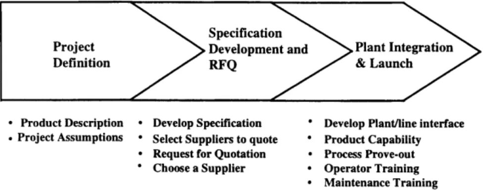
The manufacturing engineer's design process then follows a pattern shown in Figure 2:
Figure 2: Current Manufacturing Engineering Process
Specification
Project >Development and Plant Integration Definition RFQ & Launch
* Product Description * Develop Specification * Develop Plant/line interface
. Project Assumptions * Select Suppliers to quote * Product Capability * Request for Quotation * Process Prove-out * Choose a Supplier * Operator Training
* Maintenance Training
The line design stage begins with the project definition phase, where product volumes, lifecycle, and other business assumptions are listed. By using the business plan and other resources, the Strategic Business Unit or division determines which plant will manufacture the product. The team also determines if the plant or the supplier will complete the integration, the type of line desired, and the requirements for the specification.
The manufacturing engineer then develops the process specification. This document defines a general description of the product and equipment, the standards and compliance requirements, a documentation listing, project management expectations, and process specifications including capacity, reliability, and any known operator or material handling interfaces. The specification becomes the reference document for the quotation, cost, timing, financial and other development issues for the remainder of the project.
For most projects, the manufacturing engineers focus on the Overall Equipment
the FPS objective of OEE > 85% for manufacturing operations. As a result, almost all equipment specifications define performance in terms of OEE. For any machine or system, OEE is
calculated by:
OEE = (AvailablityXPerformanceXQuality )
EE = OperatingTime IdealCycleTime x TotalParts TotalParts - Defects
( AvailableTime OperatingTime TotalParts
Once a specification has been created, the engineer selects the suppliers (basic equipment or system integrators) to provide quotations. The engineer typically selects from a base of
familiar suppliers who have previously worked on the product family or with the manufacturing plant in the past. In cases where the plant will be completing the integration, machine builders
are chosen to provide quotations. Vendor selection often determines the type of line purchased when system integrators are used, as they usually specialize in one type of assembly or machining system.
After a concept has been selected and a system integrator chosen, the project enters the integration and launch phase. Plant management and operator systems are designed around the chosen concept, including inventory management, scheduling, operator tasks, and maintenance requirements. These control and management systems are bounded by local plant conditions
(union agreements, government requirements, etc.) for operator tasks, the plant information system for data gathering, and the existing management structures for shift patterns and other operational issues.
The Operations Engineering section, unlike the manufacturing engineer, has a different role before the launch of a new line. Their specialization in simulation and optimization has their project involvement primarily in the process improvement phase. As simulation has become more accepted, however, the Operations Engineering section has worked with manufacturing engineers to study proposed process designs and find areas of improvement.
2.2. The Line Design Environment
This section addresses two topics: the engineer's work environment and the
manufacturing engineer's ability to change the business systems affected by a new line design. A set of stakeholders in a new manufacturing line is defined. Addressing work environments
defines how analysis tools must work in process design, while the affected systems suggest considerations for the design methodology.
2.2.1. Engineering Work Environments
To develop a process design methodology for use by manufacturing engineers and to include analysis tools which are managed by the Operations Engineering section, the differences in the two work environments must be understood. A series of interviews were completed to develop insight into the roles of the two groups.
The Language Processing Method (Center for Quality of Management, 1996), a structured method for understanding language data, was used to study the manufacturing engineer's work environment. As derived from the interview data, manufacturing engineers see themselves as innovators and implementers of new technology. The engineers have the
perception that business and financial systems are challenges that must be negotiated with to develop new projects. They face an uncertain environment where project assumptions,
management objectives, and product designs are constantly changing regardless of their project's schedule. As a result, the engineers find themselves making difficult decisions in short periods of time, and need rapid analyses of proposed process designs.
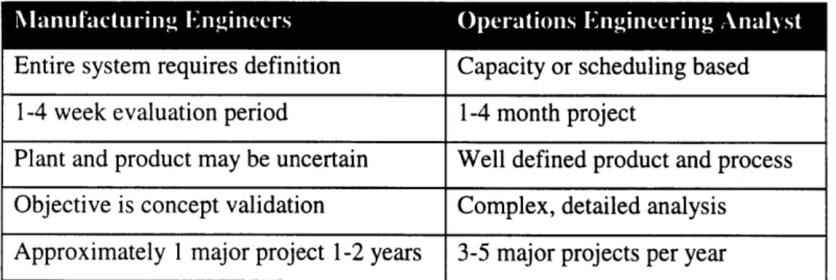
In comparison, an Operations Engineering project on an existing process may take up to four months, involving several detailed iterations. The analyst may take a month or more to build a simulation model, where the manufacturing engineer may have to chose a line concept in a week or two. Finally, an Operations Engineering project is focused on one project client, usually a plant, while the manufacturing engineer must consider an entire set of stakeholders. Table 1 summarizes the differences between the groups.
Table 1: Comparison of Manufacturing and Operations Engineering
Entire system requires definition Capacity or scheduling based
1-4 week evaluation period 1-4 month project
Plant and product may be uncertain Well defined product and process Objective is concept validation Complex, detailed analysis Approximately 1 major project 1-2 years 3-5 major projects per year
2.2.2. Stakeholders in Process Design
In looking at line design, various authors have listed sets of influencing elements. In the implementation of a Flexible Manufacturing System (FMS), Thomas (1994) found three
principal elements driving a new technology decision: corporate control over the fate of the plant, the plant's limited autonomy in choosing technology, and the state of union-management
relations. In contrast, Nyman (1992) considers plant departments; including production, product engineering, scheduling control, marketing and sales, the union, human resources, and quality control in describing cell design. For the design of a Visteon process, the engineer must consider six affected stakeholders: customers, plant operations, operators or work teams, product
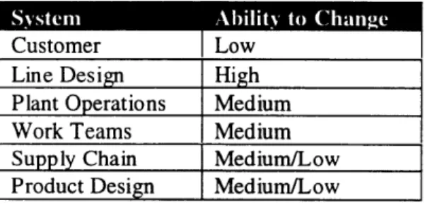
purchased part supply chain, line design, and product design. The customer purchases the products the new line will produce. The plant and operators refer to the facility and people who will run the new line, while the supply chain involves the purchased parts for the line. While line design is the responsibility of the manufacturing engineer, the other stakeholders have business processes in place with which the new line must interface. The ability of the engineer to change each of these business systems is different, as shown in Table 2.
Table 2: Engineer's Ability to Change Stakeholder's Systems
Customer Low
Line Design High Plant Operations Medium Work Teams Medium Supply Chain Medium/Low Product Design Medium/Low
2.3. Visteon's Relationship with System Integrators
2.3.1. The Equipment Purchasing Process
In general, Visteon outsources the design and manufacture of its manufacturing
equipment to system integrators and/or machine builders. The level of integration that suppliers provide ranges from off-the-shelf standard machines to entire manufacturing systems. In some
cases, the system integrator designs the system, chooses the machine builders, purchases material handling equipment, develops control systems, and integrates the line. The relationship is based on the Visteon engineer's recognition that the suppliers add value with their expertise and creativity, and develop the best line for the particular situation.
When purchasing a manufacturing line, the Visteon engineers specify the major manufacturing, assembly, and test sub-systems for the vendors to quote. For example, when purchasing a new component process, the engineers broke the line into three sections, armature
manufacturing, assembly, and test. The engineers specified a different type of process for each of the three sub-systems. The armature manufacturing line was specified as an asynchronous loop to gain the advantages of Visteon defined independent machines. For the assembly line, the system integrator was responsible, with Visteon design approval, for both the machinery and system integration to leverage their small part assembly expertise. Since it has a high level of expertise in such machines, Visteon specified the test system design in detail.
This example shows several important factors in purchasing manufacturing lines. When the system integrator is free to propose a design, as in the assembly system, the result will be based on the integrator's particular technology. For the test line, the Visteon engineers specified the detailed machine design to implement their expertise in performance testing. For the armature process, the Visteon engineers specified individual machines for the system integrator to put together. It should be noted the assembly and test lines were successfully installed, while the
armature line had throughput issues during the initial production launch. In the successful lines, one party had control over the entire design process, while in the armature line design
responsibility changed after the machines were selected.
When the Visteon manufacturing engineer wants to outsource a new or innovative process, the capabilities of the system integrator may stretched. This can be viewed in two
dimensions, in scope and capability. In operating large systems, manufacturing plants see many types of challenges and programming problems which the integrators may not recognize as important. Thus, they may be designing beyond their scope, not having the required knowledge in plant logistics, union relations, and maintenance procedures. Also, when implementing new practices, like lean cells, the integrators may have limited expertise in that type of line or
operation. This situation requires a higher level of knowledge transfer from the Visteon engineer to the supplier.
2.3.2. The Development Process from the System Integrator's Perspective
System integrators view the development process differently than Visteon engineers. A group of system integrators were interviewed to develop an understanding of their line design process. In general, the system integrators focus on meeting capacity requirements from the time a Request for Quotation (RFQ) is received to line delivery. Reliability and quality specifications are considered as part of the feasibility of proposed designs. The integrator's process designers also noted the large number of specifications as an inhibitor in the design process. In addition to the system specification from the engineer, Ford corporate, divisional and plant specifications are included to ensure the design conforms to Visteon's safety, maintenance and operating standards. To a machine builder, changing a standard design machine to meet these specifications adds considerable cost.
System integrators also add cost into quotations to cover for risk. Risk may be the result of a new concept like cellular manufacturing or open specifications as in unlimited flexibility. When responding to a request for quotation, the system integrator is under severe time
constraints that require conservative estimates. One solution to this challenge is for the integrator to assume that since previous work has been acceptable, they should plan on that level of
compliance and budget to cover unknown but expected changes to meet the specification. The Visteon engineer's relationship with the system integrator must recognize these challenges. The engineer is purchasing a new line while brokering the relationship between the purchasing plant and the system integrator. From the integrator's perspective, Visteon specifies items that add some cost and time to the development process. However, the plant, operators, and supply chain have requirements that may not be obvious to the system integrator. To the plant, mechanical and controls specifications represent the facility's accumulated knowledge regarding equipment design. For example, plants reduce spare parts inventory by only using specific standard parts. Equipment specifications are designed to minimize total life cycle costs, which includes purchase, maintenance, operation, and inventory costs. Thus, plants may only allow one or two manufacturer's air cylinders on equipment, and the vendor may have to change a standard design.
2.4. The Current Use of Analysis and Improvement Tools
This section overviews the project and analysis tools used by the Visteon Operations Engineering group. A summary and analysis of the projects the Operations Engineering group has recently completed is given. The section concludes with a review of the tools currently used for process analysis.
2.4.1. Current Uses of Simulation Tools
Within Visteon, discrete event simulation is used for process design verification. When a Visteon plant is performing the integration, they typically simulate the new process. For designs sourced to a system integrator, the supplier is required to verify the capacity and operation of the process with a simulation study. System integrators also verify material handling and
programming strategies with the simulations, but only for the sub-system that they are designing. One problem with this approach is that the entire system may not be simulated, only the different sub-systems. The implicit assumption is if all the sub-systems work to specification, the plant will not have any problems running the complete system. Since after launch the plant controls the new line, the manufacturing engineers may not be aware of sub-system integration issues. These issues are also less obvious than sub-system capacity issues and can be worked around by having the plant hold inventory or work different shift patterns.
A primary user of simulation within Visteon is the Operations Engineering group. However, the focus of their projects has been on improvements to existing systems. Operations Engineering projects that have involved design have had limited success, since the new process design often changes before a simulation model can be completed.
2.4.2. The Current Role of Visteon Operations Engineering
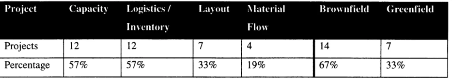
The Operations Engineering section performs projects for all of Visteon, though most of its work has been done in the Electronics, Plastics, and Climate Control plants. A survey of current and recently completed projects is given in Table 3. The projects are categorized in two areas: the types of analysis required and whether the project involved a greenfield or brownfield site. The second distinction is important since existing plants in the United States are generally older, United Auto Workers organized, and have processes already in place. With the
into new markets, including Latin America, Asia, and Eastern Europe. These new operating plants are often greenfield sites where Visteon has a joint venture partner. Projects for the new facilities offer an opportunity to do a clean sheet analysis.
Table 3: Operations Engineering Project Summary
Projects 12 12 7 4 14 7
Percentage 57% 57% 33% 19% 67% 33%
Since the typical Operations Engineering project includes more than one type of analysis, the
percentages sum to greater than 100%. The table is an analysis of 21 recent projects undertaken by the section in 1996 and 1997.
A majority of the projects the Operations Engineering group completes involve discrete event simulation, typically done using the Witness program. A diagram of the manufacturing development process was shown in Figure 1 (section 2.1.1). The initial uses of simulation at Ford were in the area of process improvement, after the process had been designed and placed in operation. Over time, the use of simulation has moved upstream in the design process to where it is used to validate proposed designs before they are implemented. At this point in the process there is greater leverage and ability to change a line design for capacity or efficiency
improvements.
The Operations Engineering section is looking to the design methodology to move the use of Operations Research analysis into the process design stage. One of the section's primary responsibilities is to provide analysis tools and training to manufacturing engineers, which makes the group a resource for Visteon. The next section reviews some of the Operations Engineering group's analysis tools used and the issues regarding their acceptance by manufacturing engineers.
2.4.3. Current Analysis Tools
This section reviews the most frequently used analysis tools of the Visteon Operations Engineering group. The tools and issues surrounding their use are discussed.
Discrete Event Simulation -Witness. The primary tool used for process analysis is the Lanner Group's Witness discrete event simulation program. Since Witness is its standard
simulation package, Ford offers training courses at the Fairlane Training and Development Center, user support through the Ford Simulation Users Group, and an on-site help desk staffed by a Lanner employee. Witness is difficult to learn, as an initial class takes 32-40 hours and does not provide the required expertise and background in collecting data and choosing the type of model to build. Witness is used both for process improvement and to verify process proposals.
For any general simulation tool, the inputs and outputs of a model depend on the
questions the analyst is trying to answer. Since the program can model almost any continuous or discrete process, the analyst must determine the appropriate level of detail, the data required, and the scenarios to test. Such analysis requires experience to determine where resources and effort are appropriately placed, making the program difficult for most manufacturing engineers without the aid of an outside programmer.
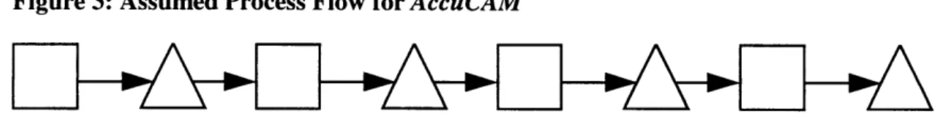
Custom Programs - AccuCAM: AccuCAM is an analysis tool developed by the Visteon
Operations Engineering section. Written in Visual Basic, it is an Excel macro program that provides a serial line capacity analysis. The program provides information on actual capacity, maximum capacity with infinite buffers, and capacity with no buffers between stations.
AccuCAM assumes a transfer line with a configuration given by Figure 3: Figure 3: Assumed Process Flow for AccuCAM
Where operations are denoted by squares, and buffers are denoted by triangles. Many of the existing processes within Visteon are transfer lines, albeit on a smaller scale than in a vehicle assembly plant.
AccuCAM is distributed through the Ford intranet, as a download from the Operations
Engineering web site. The users of AccuCAM are the Operations Engineering analysts and a small number of manufacturing engineers. Without a push to engineering, few groups will discover a need for such a program unless they begin to question the traditional relationship with system integrators, which places the analysis and throughput responsibility on the suppliers.
Material Flow Analysis -Factory Flow: To analyze material flow through a plant, the Operations Engineering group utilizes Factory Flow, an AutoCad add in. Given an AutoCad
layout, the analyst can study the traffic and flow patterns through a plant to relieve congestion and minimize travel distance.
The program requires the plant layouts and flows through the plant for each product being studied. Given the costs of transporting the material, the program will calculate the costs of material handling throughout the system. The most used output is visual indications of the flows, with line thickness indicating amount of traffic. This analysis provides an intuitive, easily
interpreted indication of plant traffic and improvement opportunities.
Typically, this tool is used in new joint venture plants to verify and improve the proposed layouts. Existing plants have limited opportunity to benefit Factory Flow, due to the mix of old and new lines. Since large scale rearrangements of existing processes are time consuming and expensive, most plants are unable to radically change the layout for each new process. Given this limited opportunity, and the high cost of the program, few engineering departments or plants utilize Factory Flow.
2.5. Quality Function Deployment and the Analytical Hierarchy Process
Two tools are reviewed here for use in the proposed process design methodology. Quality Function Deployment (QFD) is an objectives driven approach to design, used to map customer needs into product designs. The Analytical Hierarchy Process (AHP) is a decision making tool, permitting a complex problem to be broken down into smaller, more manageable decisions. The
use of these tools also facilitates communication between the different groups involved in the development of new manufacturing processes.
2.5.1. Quality Function Deployment
Quality Function Deployment is traditionally used in product development as a means of translating the "Voice of the Customer" into engineering characteristics and design attributes. Beginning with customer needs in the language in which they are stated, the QFD process translates these needs through engineering and process characteristics, down to manufacturing characteristics. A visual process, QFD allows communication and understanding of how the product design meets the needs of the customers, as well as how different characteristics interact.
One of the most important aspects of QFD in product and process development is it requires asking the customers what they want, and not trying to interpret or presume these needs.
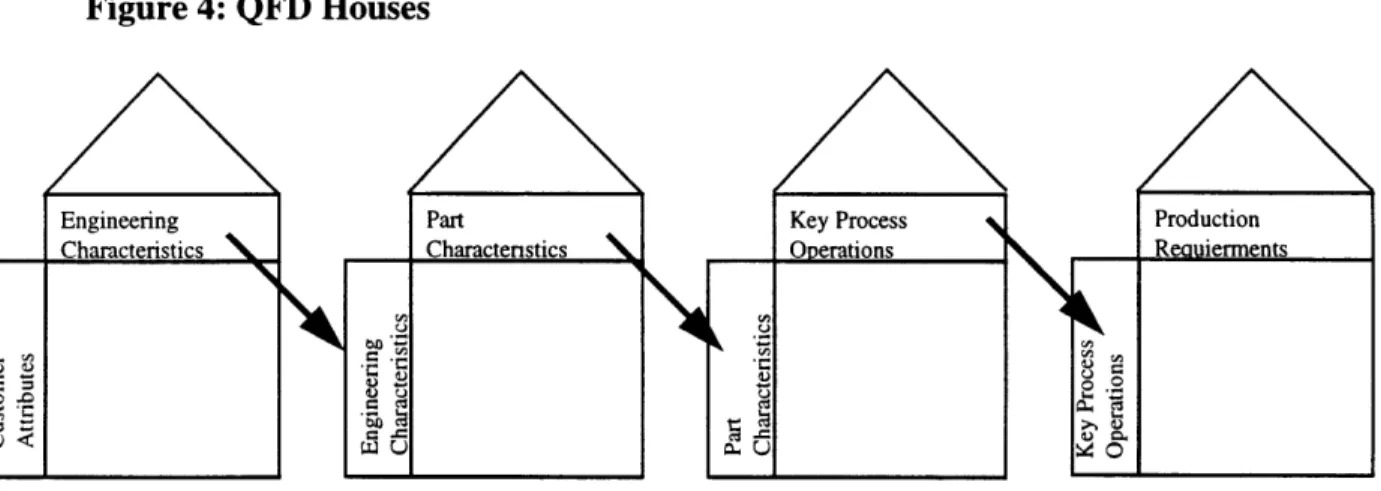
Traditional QFD uses four houses to link the customer's voice to production requirements (Hauser and Clausing, 1988). As shown in Figure 4, the process begins with the recording of customer needs, usually categorized in hierarchical format, defining primary, secondary, and tertiary levels of needs. The customer attributes are then linked with engineering characteristics, which are product details that can be modified to affect the associated customer attribute. An important part of the process is reviewing each engineering characteristic on how it affects each customer attribute, and the interaction with other engineering characteristics. In the second house, the engineering characteristics from house one move to the left side of house two. The top row is now part characteristics. The third house translates part characteristics into key process operations for the manufacturing process. The fourth and final house takes key process operations and translates them into production requirements.
Figure 4: QFD Houses
Engineering Part Key Process Production Characteristics Charactenstics Operations Rauierments
a
Adapted from Hauser and Clausing, 1988
Griffin and Hauser (1993) list four roles of QFD. The first is its stated use of developing specified target values for each of the design attributes. Another is using QFD to guide the design process and make decisions. A third is to facilitate communication between different corporate departments, and finally QFD is used to provide specifications for design attributes. Ulrich and Eppinger (1993) use a similar needs-metrics matrix as part of the specification development stage of their product development process.
The use of the first two houses of QFD is well established in the product engineering community. Classroom training in the QFD process is available at the Ford training center, and software to facilitate the process is also available. In practice, QFD is rarely used to drive the entire design process, but it ensures customer needs are discovered and met in a product design.
It is also useful in integrating the product and manufacturing design processes when used to completion. The QFD process is also extremely useful in facilitating communication between
different groups within and outside of Visteon.
2.5.2. The Analytical Hierarchy Process
The analytical hierarchy process (AHP) is a means of breaking a complex decision problem down into smaller, more manageable sub-problems, which allow pairwise comparison
of alternatives. Developed by Saaty (1980), AHP is a logical framework that decomposes a problem into a hierarchical structure, and uses a linear weighting scheme to evaluate overall
alternatives. There are three principles in AHP: decomposition, comparative judgment, and synthesis of priorities. By breaking down a problem, evaluating the alternatives relative to one another, and then synthesizing the results, AHP allows a logical decision to be made from a group of alternatives.
AHP assumes a set of alternatives has been determined, and each is a capable solution. The process is of value in choosing between complex alternatives from which no best answer is clear. It allows the team to discuss and evaluate various aspects of a decision in small segments, and to evaluate the alternatives on a relative basis. The procedure then synthesizes the results into a final general result, rating each segment by its relative weight.
The decomposition of a problem is structured as a hierarchy, as shown in Figure 5:
Figure 5: AHP Example Hierarchy
Goal
General Criteria
The hierarchy begins at the top level with the overall goal of the analysis. General criteria, the second level of the hierarchy are then determined, as are the sub-criteria for each of the general criteria. The sub-criteria can be taken through as many levels as are required to break the evaluation down to a level where the different alternatives can be evaluated.
After the hierarchy has been determined, the criteria must be evaluated relative to each other. The scale proposed by Saaty (1980) is commonly used (Figure 6).
Figure 6: AHP Ratings Scale
Verbal Scale Numerical Scale
Equally important, likely or preferred 1
Moderately more important, likely or preferred 3 Strongly more important, likely or preferred 5
Very strongly more important, likely or preferred 7
Extremely more important, likely or preferred 9 Intermediate values to reflect compromise 2, 4, 6, 8
Less important Reciprocal of above
The next step for the team is to rate each of the general criteria using the above scale. Selecting a base criterion and rating the other general criteria relative to the base does this. If a
criterion is determined to be less important than the base, the appropriate reciprocal is used. After each of the criteria is rated, the same process is used for each of the sub-criteria levels. For each general criteria and sub-criteria, the relative weightings are found by taking the individual ratings divided by the geometric mean of the total. From the hierarchy, it can be seen that the sums of the sub-criteria weightings are the relative importance scaled by the criteria weighting.
Using the same scale, each of the alternatives is then rated for the lowest level sub-criteria. The sub-criteria and general criteria weights then multiply these relative ratings. All of the weights for each alternative are summed to get the general, total score for each alternative, with the largest score being the best choice.
The entire decision need not be done from one hierarchy. If desired, benefits, costs, and risks can be evaluated with different hierarchies (Saaty, 1994). The best solution can then be
found by synthesizing the results for each hierarchy, and taking the appropriate benefit/cost or benefit/risk ratio. This permits a separate analysis of each segment of the problem.
There are two significant benefits from the AHP approach to making a decision. First, the process is easily automated in a spreadsheet format. This permits easy programming and
modification, as well as promoting easy distribution throughout Visteon. Secondly, AHP, like QFD, promotes team communication. When determining the hierarchy and weights, the team discusses different aspects of the project in a defined manner, taking each concern in turn. This formal approach leads to more open and straightforward communication. The AHP process works best when there is one recognized facilitator who can keep the team on track and arbitrate any disagreement to keep the process moving.
2.6. Benefits of a Process Design Methodology
2.6.1. Guidance for Manufacturing Engineers
One of the major benefits from a process design methodology is providing guidance for manufacturing engineers. At a minimum, a methodology provides a checklist of what must be accomplished designing a new manufacturing line. Lacking a methodology, the engineer defines what must be done, creating the opportunity to miss requirements or delay the program. A process design methodology also lists tools for use in the design process, which aids the engineer in understanding how to achieve the goals of the project.
As Rao and Gu (1995) note, a manufacturing engineer faces an enormous amount of data regarding objectives and constraints. A design methodology helps put this information into perspective, focusing the task of process development. This is important in a large organization where different departments are involved in process design.
Ulrich and Eppinger (1993) give three reasons for the use of structured methodologies in product design, and they apply to process design as well. First, methodologies permit everyone on the team to understand and support decisions. Second, a methodology acts as a checklist on the design process. Finally, a methodology makes the process self-documenting, permitting learning across projects.
2.6.2. Systems Thinking in Process Design
Another benefit of a design methodology is it forces systems thinking onto the manufacturing engineer. Much like QFD, a design methodology supports both high level
strategic thinking and the detailed work required of the engineer. A design methodology requires focused thinking on plant and supply chain performance, as well as on individual machines. This is a different focus for many manufacturing engineers, who are trained in detailed machine design.
A design methodology also requires the process be total cost driven and not Labor and Overhead focused. Before the implementation of the Ford Production System, the driver of plant performance was a traditional labor based accounting system that emphasized labor costs in performance evaluation. FPS, in contrast, emphasizes minimizing total cost, which includes capital, labor, and other manufacturing expenses.
By focusing on needs, objectives, and constraints, a design methodology would also
overcome any parochialism in the development process. New concepts are required in the changing competitive environment Visteon faces, which forces change in the engineering and management disciplines. As noted by Grossman (1997):
Many times, potentially wonderful ideas get discarded because technical people are trained to look for what's wrong with new ideas instead of what's useful.
Finally, a methodology leaves the design expertise with the manufacturing engineer, whose knowledge and experience are well above what any general method could provide. Rao and Gu (1995) summarize this point with:
A proposed design methodology can only outline and specify the needs of modeling and structuring the manufacturing system. It is up to the modeler or designer to come up with approaches to implement the objectives and logical reasoning outlined in the methodology.
3.
Proposed Manufacturing Line Development Methodology
This chapter proposes a design methodology for manufacturing processes. Several product and process design methodologies are presented, and then an overview of the proposed
methodology is given. Each step of the proposed methodology is described, defining the inputs and outputs for each stage.
3.1. Product and Process Design Methodologies
Successful product design methodologies have focused on determining the needs of the customer, and then directing design efforts on meeting those needs. In contrast, most process design methodologies begin by assuming the type of line required, and then build a framework around creating a specific type of process. Several methodologies are reviewed here for
background.
3.1.1. Product Design Methodologies
Product design methodologies are a relatively well documented subject, and this research drew ideas from two different sources. The Ulrich and Eppinger (1993) product design
methodology determines the needs of the customer and designs a product based on those needs. The generic product development process given in their text provided the starting point for this methodology.
Shiba, Graham and Walden (1993), also emphasizes determining the voice of the
customer by interviews and language analysis. This research used their process to understand the environment of a Visteon manufacturing engineer, the system integrator, and the plants within the company. These results provide insight into the tools an engineer needs for process design, as contrasted with those used by the Operations Engineering section.
3.1.2. Process Design Methodologies
Rao and Gu (1995) propose a design methodology for manufacturing systems that they then use with a genetic algorithm approach. Their methodology includes five stages, not unlike those typically proposed for product design:
System Conceptualization: The designer identifies the needs, goals, and objectives
for the proposed system. At this stage constraints are also identified.
System Structure: This is the development of system specifications from the
known needs and constraints.
System Implementation: At this stage the engineer develops detailed specifications
of the process, including hardware, communication, control, and personnel. Testing also occurs at this stage.
System Operation: The actual operation of the system, this stage also includes
verification of the system performance.
System Reconfiguration: This stage is intended to identify the changes that are
required for the system to accommodate differences from the forecast needs and constraints.
In Making Manufacturing Cells Work, Nyman (1992) proposes a set of steps for
implementing cells in an existing plant. In this approach, the team works on macro facility planning, conceptual cell development, concept evaluation, material handling and control systems, and finally, detailed design. Nyman's application also provides useful spreadsheet analyses to aid the engineer in designing a system of manufacturing cells for the plant.
Most proposed process design methodologies assume a manufacturing process technology. An example for flexible manufacturing systems is Tempelmeir and Heinrich's
Flexible Manufacturing System Decision Support for Design and Operation (1993), which
details the process of implementing FMS systems and reviews performance analysis methods. The new methodology this thesis proposes attempts to determine the technology based on the project needs, and then lead the manufacturing engineer to the type of line required.
3.2. Proposed Methodology Overview
3.2.1. Background
This new process design methodology is a top-down, objectives based approach to manufacturing line design. The methodology considers the needs and constraints imposed by the product customer, plant management, operators, supply chain, and product design. To
accomplish this, the manufacturing engineers must obtain input from across organizational boundaries and functions.
The methodology is structured to use a set of tools for facilitation and concept analysis. Use of a structured method facilitates communication between cross-functional team members, as well as ensuring all the process steps are completed. Analysis tools provide objective criteria for the team to compare proposed design concepts, leading to better decisions earlier in the design process.
Process design includes establishing a cross-functional team with members from various business functions. A typical team includes personnel from manufacturing and product
engineering, plant management, operators and skilled trades, finance, and controls engineering. The process is facilitated by the manufacturing engineer, with the involvement of other team members as required in each step of the methodology.
The methodology requires designing a system to satisfy each of the stakeholders affected by the process. Customers, the purchaser of the manufactured product, demand quality and delivery reliability. Operators require useable interfaces with the equipment and information systems, and must accept the new work environment. Each plant has a different management structure and philosophy that must interface with the process, including information flows and process control systems. The purchased part supply chain can place constraints on the scheduling and inventory control of the production system, while current and future product characteristics may limit the process design.
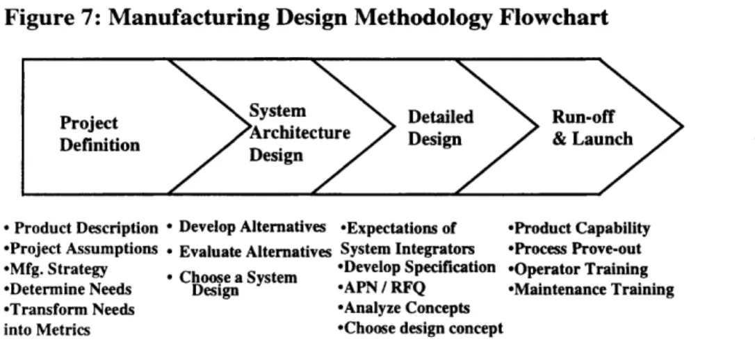
The overall flow of the methodology, with the major steps, is given in Figure 7.
Figure 7: Manufacturing Design Methodology Flowchart
* Product Description * Develop Alternatives *Expectations of *Product Capability -Project Assumptions * Evaluate Alternatives System Integrators *Process Prove-out *Mfg. Strategy * Choose a System *Develop Specification *Operator Training
*Determine Needs Design *APN / RFQ *Maintenance Training
*Transform Needs *Analyze Concepts
As indicated in the flowchart, the process begins by defining the project, including the product and business assumptions. In project definition, the division's manufacturing strategy must be identified to ensure the new process aligns with business objectives. This typically includes identifying the types of processes used, the current and future product mix, and available labor and other resources available. Finally, the engineer transforms needs into design metrics using the QFD process.
The system architecture design stage considers material flow, inventory control and other system performance issues. The designer creates and evaluates a set of design alternatives based on the system level metrics from the project definition stage. In the final step, the engineer selects a system level design for the new process.
The detailed design stage includes specification development, vendor evaluation, request for quotation, and final concept selection. The engineer first determines expectations for the system integrators, and selects appropriate vendors to quote the new process. To ensure a
complete specification, the engineer develops requirements based on the transformed needs from the project definition stage. After the quotation process, concept analysis leads to the choice of a vendor.
The build, run-off and launch phase includes the evaluation and installation of a new line. This includes developing acceptance criteria and evaluating product capability. Working with the plant, the engineer must also develop operator and maintenance training. This is the final phase before regular operation.
3.2.2. The Use of Quality Function Deployment
The new methodology utilizes Quality Function Deployment (QFD) to map needs into the system level and detailed designs of a new process. As shown in Figure 8, the process takes the customer's needs on the side of the first house, and translates them into system architecture level characteristics. The first house consists of primarily customer, plant, and supply chain
requirements, since they are concerned with overall system performance. The engineer evaluates system level design alternatives based on the system level characteristics, as well as transfers these characteristics to the second, detailed design QFD house.
The second QFD house takes the system architecture characteristics, and relevant detailed needs, and translates these into detailed level characteristics. The second level needs are
primarily product design, process, and operator needs. The use of QFD in this way can also aid in the concurrent engineering process. As product and process design requirements are developed, they can be evaluated for their effect on the other process. For example, product design
requirements can be evaluated in terms of the process requirements, identifying areas to consider for revision in the product design.
The third and final house takes the detailed level characteristics, and transforms them into specification requirements for the system integrator. This use of the QFD process ensures
stakeholder needs are translated into the specification for the end system.
Figure 8: QFD Method for Process Design
System Level Feeds System Level
Characteristics Concept Analysis
Detailed Level
Detailed Level Feeds Detailed Level aracteristics
Concept Analysis
Specification
SI Requirements
Primarily Customer, -al ll-l
Plant, and Supply Chain
Primarily Line and Operator
3.3. Project Definition
The first design methodology stage is project definition. Project definition includes establishing the project scope and mission and identifying the stakeholder's needs.
3.3.1. Establishment of Scope and Mission
A brief but important stage of process development is establishing project scope. The engineer identifies project assumptions, manufacturing strategy, and the product description with input from the business planning and product engineering functions. It is important for the engineer to specify the type of process development required. Ulrich and Eppinger (1993) summarize different types of product development as market pull, technology push, platform
products, process intensive, and customized. Similarly, manufacturing processes can be classified into different development types.
For Visteon, most new lines can be considered platform development processes, where the new line manufactures a product similar to its predecessor. The development of cellular lines represents a market pull, where Visteon is designing for changing market requirements. New process technology often follows a technology push product, since existing processes cannot manufacture the new product. In the end, the engineer modifies the development process based on the type of line, with less design effort required for platform development. The output of this stage of the methodology is a listing of assumptions, strategies, and development requirements that guide and constrain the line design.
3.3.2. Identification of Stakeholder Needs
The manufacturing engineer must identify the needs and limitations of the various stakeholders in the new manufacturing process. For most process designs, members of various affected business functions can participate in the needs identification process.
The team begins by entering needs on the left side of the first QFD house. The FPS principles are included, as they define the operation for all Ford manufacturing facilities. The team segments needs by stakeholder, which provides structure to the brainstorming session.
In addition to needs, the team lists constraints the design must consider. While the recording of constraints is important, each should be questioned and understood by the team. At this stage of the process, Shiba's (1993) 'I Already Know It' learning block often occurs. This learning block arises when someone fails to understand and apply existing information to the current problem, because they think they already know the answer.
After the needs have been listed, the group goes through each of them and develops metrics for the design. This requires expertise in each aspect of the process to ensure the development of a good design. Again, there is an advantage over product design in the limited number of people involved. Rather than having to interpret customer statements, the department involved can directly translate the requirement and explain to the rest of the group.
Ulrich and Eppinger (1993) list caveats for product design metrics, which apply here also: * Metrics should be dependent, not independent variables
* Some needs cannot easily be translated into quantifiable metrics
The team lists target values for each metric in the QFD house. The team also considers whether each metric affects a system architecture or detailed machine design parameter. Listing an S for the system architecture level or D for the detailed level beside each metric permits separation in the later design stages. While some team members find these steps obvious, the common understanding developed throughout the group is important.
Benchmarking information is taken into account at this stage. In process design, benchmarking may include visiting unrelated product manufacturing sites to understand the
implementation of different concepts like operator managed work teams, lean manufacturing cells, or specific order and delivery systems.
As a final stage of metric determination, a check is made to ensure requirements have not been missed. These may include process, monitoring or control system, material handling,
software, material flow, layout, maintenance, management, safety, implementation, and cost requirements.
3.4. System Architecture Design and Testing
After the design metrics have been determined, the engineer begins the overall system architecture design. System design determines how material will flow through the plant and the process technology involved. A set of alternatives is created, considering layout and other restrictions, with a final selection completing this phase.
3.4.1. System Architecture Considerations
Determination of Process Requirements: The engineer first must determine the
operations or processes that are required to produce the product. Rao and Gu (1995) describe how system operational requirements govern the design of an entire manufacturing system. This
includes recognizing that all forecasts in customer demand will be uncertain, and the operational requirements must be determined to accommodate such variability.
The first step is listing the physical processes required to produce the products. This includes processing steps, desired lot sizes, materials, part sizes, and gages. These are laid out in