HAL Id: cea-02431790
https://hal-cea.archives-ouvertes.fr/cea-02431790
Submitted on 8 Jan 2020HAL is a multi-disciplinary open access archive for the deposit and dissemination of sci-entific research documents, whether they are pub-lished or not. The documents may come from teaching and research institutions in France or abroad, or from public or private research centers.
L’archive ouverte pluridisciplinaire HAL, est destinée au dépôt et à la diffusion de documents scientifiques de niveau recherche, publiés ou non, émanant des établissements d’enseignement et de recherche français ou étrangers, des laboratoires publics ou privés.
loop integrating an optimized irradiation process.
S. Gaillot, L. Diaz, T. Dousson, N. Waeckel, S. Gay, S. Vitry, F. Delassalle
To cite this version:
S. Gaillot, L. Diaz, T. Dousson, N. Waeckel, S. Gay, et al.. Jules Horowitz reactor.development of an experimental loop integrating an optimized irradiation process.. RRFM-IGORR 2016, Mar 2016, Berlin, Germany. �cea-02431790�
BERLIN, GERMANY 13-17 March 2016
JULES HOROWITZ REACTOR , FRANCE.
DEVELOPMENT OF AN EXPERIMENTAL LOOP
INTEGRATING AN OPTIMIZED IRRADIATION PROCESS.
S.GAILLOT (a), L.DIAZ (a), T.DOUSSON (b), N.WAECKEL (c), S.GAY (a), S.VITRY (a) & F.DELASSALLE (a)
(a) CEA, DEN, DTN, Nuclear Technology Department DTN/STCP/LCIT, building 204, CEA CADARACHE
F-13108 Saint-Paul-lez-Durance, FRANCE
[email protected], [email protected]
(b) CEA, DEN, DER, Reactor Studies Department DER/SRJH/LEDI, building 1222, CEA CADARACHE
F-13108 Saint-Paul-lez-Durance, FRANCE [email protected] (c) EDF, SEPTEN avenue A. Dutrievoz, 69100, VILLEURBANNE, FRANCE [email protected] ABSTRACT
Experimental reactors enable researchers to address industry and scientific organiza-tion’s needs, by providing support to the existing nuclear reactors (Gen.2), by prepar-ing the future generations of reactors (Gen.3, Gen.4) or by supportprepar-ing fusion related issues and medical applications. It is for this specific purpose that the Jules Horowitz Polyvalent Irradiation Reactor (JHR) is under construction at the CEA Cadarache Re-search Center (located South of France). This Material Testing Reactor (MTR type) is designed to irradiate materials or fuel samples to conduct various types of experimental tests. The reactor will also produce Mo99 radioelements that will supply 25% to 50% of current European needs.
The purpose of this paper is to describe a new fuel irradiation loop, called ADELINE1, specifically dedicated to study fuel rod behavior under power ramp transients. The de-sign of the instrumented loop is still ongoing but the test device will be fully operational when JHR will start. ADELINE loop is planned to perform various types of power ramps, from slow to high ramp rates, from low to very high power changes, on different types of fuel concepts such as regular fuel, PCI resistant fuel, Enhanced Accident Tolerant fuel concepts, etc…). The main feature of the test device is to provide the industry with well characterized ramps tests allowing defining reliable SCC-PCI (Stress Corrosion Crack-ing-Pellet Cladding Interaction) failure thresholds.
In order to increase its irradiation capacity (2 to 3 power ramps per JHR cycle), each phase of the experimental procedure has been carefully optimized: for instance, non-destructive examinations are performed before and after the test in JHR hot cells, specific loading tools have been designed to facilitate the handling phases or reliable test protocols have been qualified on a similar test device (like the one used in OSIRIS). The objective is to fulfill all the customers’ needs, in a high quality experimental envi-ronment.
Key Words: Material Testing Reactor, Fuel irradiation loop, ADELINE, optimized
irradiation process & design.
2-10
1. REMINDER OF THE CONTEXT :
In the European research area, most irradiation reactors built in the 1960’s are reaching their end of life (after 50 years of operation) and the question of replacing them is now under discussion. The conditions of their renewal depend on several parameters: - needs for nuclear programs (support needed for the existing nuclear infrastructure, preparation for the future),
- needs concerning the production of radioelements for medicine (typically Mo99,…), - needs in the field of education (maintaining the competence of specialized staff and the preparation of future generations).
The construction of a new research facility is decided by analyzing the needs that exist between different contributing countries that destined to share the tool and the invest-ment. In the case of the JHR, the proposed facility corresponds to a material testing reactor type (MTR) designed to meet the needs of the various project partners in the best possible manner.
The JHR is an experimental platform open to the international community.
The JHR Project Consortium, created on March 19th 2007, involves the participation of several European countries and institutions including the CEA, EDF, AREVA (France), CIEMAT (Spain), the UK, VTT (Finland), Studsvik (Sweden), SCK-CEN (Belgium), UJV (Czech Republic) as well as other international representations such as DAE (India), IAEC (Israel) and JAEA (Japan).Today, the consortium is made up of 11 countries. The contribution of the consortium members varies in nature. It may involve direct pro-curement of a component for the facility (circulating pumps, heat exchangers, hot cells and non-destructive examination systems) while other members contribute to the direct financing of the project. For the use of the facility, the consortium members can decide on the realization of joint experimental programs or they may carry out their own pro-grams.
BERLIN, GERMANY 13-17 March 2016
2. THE JHR FACILITY :
2.1. Main performances & characteristics.
The core of the reactor consists of a compact cylindrical part (d = 60 cm, h = 60 cm) surrounded by a Beryllium annulus reflector (l = 30 cm). The core is under moderated allowing the production of high fast neutrons fluxes (typically 3.1014n.cm-2.s-1 at 100MWth). The reactor is designed for a thermal power of 100 MWth and is cooled with light water. Two operating working modes are planned, 70 & 100 MWth. Power evacua-tion is obtained by ascending water circulaevacua-tion in a closed primary circuit which is slightly pressurized (10b). The reactor is designed to handle up to 10 irradiation ex-periments in the core and up to 10 in the reflector in fixed position or on displacement systems permitting the adjustment of the neutron flux during the experiment (this is accomplished by moving the device either closer or farther away from the core).
Fig.2 : Upper view of the JHR core & reflector (CEA).
Main characteristics of the first core are given hereafter: − fuel: 36 U3SI2 fuel assemblies, annular shape,
60 cm in length, 27 % U5 enrichment, − 27 neutron absorbers,
− light water moderator,
− 70 to 100 MWth thermal power, − 25 to 30 days per cycle.
2.2. JHR allowing the integration of the entire experimental process.
The facility is made up of an infrastructure in two parts; the first being the BUR building which contains the reactor pool, the core and the area devoted to carrying out experi-ments. The second part of the installation concerns the BUA building which ensures the operation of all nuclear auxiliary equipment connected to the BUR. The transfers are performed by an underwater channel between the two buildings. The BUA also contains all the operational support means for irradiation processes (storage pools, hot cells, materials, fuels, radio-isotopes, the “alpha” cell, non-destructive examination cells and other utilities) [1].
4-10
2.3 . JHR schedule.
This mainly concerns the building site, equipment manufacturing, controls & start-up and divergence. The civil engineering is almost finished and should be complete by the end of this year. At the same time, the major internal equipment’s are either still under study or are in the course of manufacturing. Complete installation of these equipment’s in the building is in preparation.
2.4 . Startup of the JHR irradiation experiments.
After the divergence phase of the reactor, the startup phase of the experimental equipment is planned over a one trial period spanning 12 to 18 months. Once this stage is reached, the experimental loops will be operational and ready to meet the needs of future customers.
3. THE JHR IRRADIATION LOOP FOR FUEL POWER RAMPS TESTS : 3.1. Main features.
The ADELINE loop, now under study, is an experimental irradiation loop dedicated to rod irradiation functioning under LWR conditions (cf.fig.3) :
This fuel irradiation loop is composed of an in-core part located in the reactor pool and of another part located in the operation zone of the experiments (BUR, CEDE).
The in-core part includes the irradiation device equipped with a rod, the underwater lines and the fluid & electrical connections through the experimental penetrations of the pool. The other part is made up of the fluid circuit, a tight bunker and connection of the circuit with the utilities of the JHR facility. The fluid circuit is equipped with circulating pumps and pressurization systems, making it possible to obtain the circulation of water cooling towards the device and to reach the required thermal-hydraulic conditions at the bottom of the test channel (155b, 270°C, 200g/s).Th e experimental loop under study also takes into account the feedback of this kind of loop much like the ISABELLE irra-diation loop which was used on the OSIRIS irrairra-diation reactor located in SACLAY (France).
BERLIN, GERMANY 13-17 March 2016
4. ANTICIPATED PERFORMANCES OF THE LOOP :
4.1 Standard TH characteristics, power levels, duration description.
The physical parameters around the rod correspond to the following PWR conditions: 155b, 320°C with a fluid flow of 0.2kg/s and 73b, 2 80°C for BWR conditions.
The experimental rod is composed of a UO2 or MOx type, either irradiated or not.
The standard profile of power during the test is described hereafter:
• conditioning phase with low power (100W.cm-1) ranging from a few hours to a few days,
• power ramp test with kinetics going up to 700W.cm-1.min-1,
• power aimed at the high level of 620W.cm-1+/-10W.cm-1 for one maximum duration of 24h,
• withdrawal of the device according to the power decrease scenario.
Fig.4 : JHR primary circuit & displacement system (SAD)
Fig.5 : Example of power evolution versus SAD displacement and fuel enrichment (analytic
calculations).
Distance from vessel (cm) Linear power
6-10
4.2 Two types of sample holders are planned in order to offer irradiation flexi-bility.
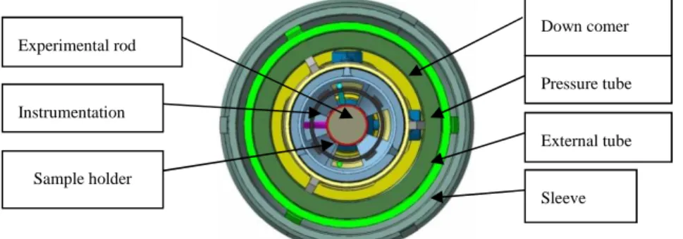
The experimental rod is fixed on a sample holder, metallic structure, which offers an axial and radial rod position during irradiation (cf. fig.6). The head of the sample holder is used as a tight closure of the device. The simplified experimental configuration per-mits the quick change of the rod in the underwater transfer system and makes it possi-ble to increase the rate of the tests. For this configuration, the rod can be equipped with lengthening sensors at its ends (of LVDT type) enabling us to measure its elongation during the test. According to the objective of the test, the rod may also be more instru-mented (fuel, clad temperature measurements, deformation).
This embedded instrumentation can characterize the consequences of the irradiation on the rod more precisely. Note that this instrumentation, placed on the sample holder is consumable.
Fig. 6: Cross section view of the device with the sample holder
(CEA - preliminary design)
4.3 Device instrumentation (PI) for following the TH conditions of the device.
In order to measure the thermal hydraulic parameters of the test channel, the instru-mentation holder part (PI) is equipped with various sensors (thermocouples upstream & downstream for the heat balance, flow meter (Vcone type). This instrumentation, in-stalled on the device, is re-usable.
4.4 Pressure tube and Zy sleeve (neutron screen, probe holder and mechanical protection).
The pressure tube of the device is designed and calculated according RCC-MRX rules in order to satisfy the criteria of the different identified working conditions. The pressure tube is made of Zircaloy to optimize the thermal neutron flux on the rod.
The sleeve, surrounding the pressure tube, is designed to cool it (downward circulation of pool water between the pressure tube and the sleeve). It is also equipped with SPND2 making it possible to measure nuclear flux during the power ramp. The sleeve has also a screen role in order to limit the gamma flux on the device. Last but not least, it also has a mechanical protection function.
2 SPND : Self Powered Neutron Detector Experimental rod Sample holder Instrumentation Down comer Pressure tube External tube Sleeve
BERLIN, GERMANY 13-17 March 2016
5. OPTIMIZED DESIGN & INNOVATION :
5.1. Hydraulic amplification system of the in-core part: jet pumps permitting
flow reduction on the cooling circuit.
In order to reduce the water flows of the ground part, an amplification flow system is implemented in the upper part of the device. Composed of an injector-conduit system, it allows entrainment of the water contained in the device by a high pressure injection of flow coming from the cooling circuit. This system can amplify the flow in the device by a factor of 4 to 5.
5.2. Adaptation of the head of the device to guarantee the tight transfer
be-tween two cycles of irradiation.
In order to accomplish an increase in the rate of tests that can be conducted through the use of the PTE (cf.fig.7), the head of the device is designed to adapt to a leak tight transfer door. To guarantee successful operation during the interface, the device and the bottom part of the PTE are both equipped with leak tight systems.
Fig. 7: Overview of the Underwater Transfer System (PTE)
5.3. On-line transmitter of clad swelling integrating a fiber optic (cf.fig.8) &
[3].
During the irradiation phase, the experimental rod can be subjected to various stresses: swelling, elongation, wear. For the purpose of following these phenomena, innovating instrumentation is now being studied. One of these R&D actions involves the use of an optical-mechanics sensor permitting the on-line deformation measurement of the rod. This low-size sensor integrates an optical module, in a pressurized and deformable tight enclosure making it possible to follow rod deformation. The range of the sensor is from 0 to 1.5mm with a precision of 10 microns. The effective range of expected rod defor-mation during the test varies from about 0 to 0.5mm.
Fig. 8 : Optical module of the sensor inserted in a body with a piston simulating the
8-10
6. ENGINEERING PROCESS OVERVIEW : 6.1 Introduction.
Adapted processes are applied to take into account the specific features of the device. These processes are of an iterative nature and concern various fields:
- the experimentation field characterizing the external customers’ requirements which concern the neutron and thermal hydraulics performances. This input data is considered in terms of device design (capsule, loop), location in the reactor (in-core or in the re-flector), pre-selection of the materials and instrumentation definition (on the device and on the loop),
- the licensing of the cell which involves defining the safety options and the require-ments that the equipment must satisfy in terms of regulation,
- the operation staff defining the constraints related to the implementation and use of the equipment in the facility during the various work phases (in particular, definition of the handling tools, storage equipment),
- the engineering field where qualified personnel are in charge of the technological is-sues involving the equipment, the thermo-mechanical dimensioning of the components, the qualification of the critical components, the industrialization, the manufacturing con-trols (fabrication and assembling phases) and the start-up on site.
This process of studies, manufacturing and start-up for a new experiment requires a long time (several years) and it involves all the actors working in or around the reactor.
6.2 Safety issues.
Application of the safety report requirements for the facility and the technical guide dedicated to use of the irradiation devices:
- identification of the off-normal scenarios,
- thermal-hydraulic analyses and preliminary safety option definitions,
- identification of requirements concerning the design of the irradiation device (shells, barriers, screens,…).
According to the CEA guide, consequences analyses of various types of scenarios:
- radiological impact following the failure of the device and/or the circuit,
- mechanical impact on the core and on safety systems due to failure of the device,
- neutron effects on the core as a consequence of device removal.
The results of these analyses (based mainly on thermal hydraulics calculations (using CATHARE3 software)) allow for the definition of a number of safety barriers and protec-tive systems. The conclusions of these analyses define the level of mechanical calcula-tions to be taken into account for the thermo-mechanical studies of the components which fulfill a safety function or play a role in the availability of the facility.
6.3 Regulation and Quality issues
The standards applied are French or European levels (NF, EN).
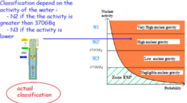
The quality process complies with the ISO9001 standard and the recent 2012-BNI Or-der4 concerning the nuclear pressure containments, the French order ESP(N) is applied.
The applicable codification (e.g. N2, cat IV) can result in increased controls during the manufacturing phase (e.g. volume control of the welds), hydraulic tests, periodical in-spections (every 40 months) based on visual and non-destructive examinations and pressure requalification tests (every 10 years).
3 CATHARE: Advanced Safety Code for Pressurized Water Reactors. 4
BERLIN, GERMANY 13-17 March 2016
Fig. 9: ESP (N) regulation application (illustration)
6.4 Simulation (hydraulics, thermal, thermo-mechanical)
Once the preliminary data has been established, the thermo-mechanical dimensioning of the structures which have safety functions (barrier) is carried out according to the rules of the RCC-MRX(*) code (v2012) in normal and off-normal conditions. During these studies, the dimensioning criteria are checked.
(*) The RCC-MRX code consists of the technical rules applicable to the design and the construction of the mechanical equipments on the experimental JHR reactor, its auxilia-ries and its irradiation devices.
Fig.11: Engineering design & calculations (extracts)
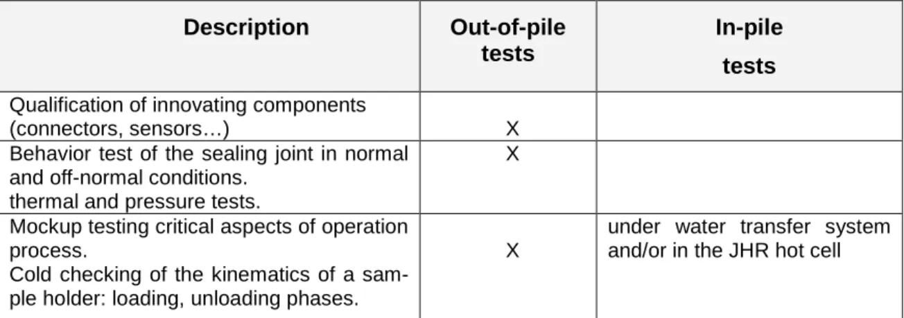
6.5 Qualification support
Technical and technological studies are performed up to the level of a detailed design report. In parallel to this, some items may result in producing a mockup of critical com-ponents to confirm the simulation studies or to assess manufacturing issues:
10-10
Description Out-of-pile
tests
In-pile tests
Qualification of innovating components
(connectors, sensors…) X
Behavior test of the sealing joint in normal and off-normal conditions.
thermal and pressure tests.
X
Mockup testing critical aspects of operation process.
Cold checking of the kinematics of a sam-ple holder: loading, unloading phases.
X
under water transfer system and/or in the JHR hot cell
Tab. 1: Qualification tests (illustration) 7. CONCLUSION :
The building of the JHR facility is well underway. In parallel, the studies and the manu-facturing of the experimental equipment’s are in progress. At the startup of the facility, a whole array of devices meeting the principal customers’ requirements will be available. In particular, the loop of fuel irradiation called ADELINE functioning in LWR conditions will permit researchers to carry out power ramps tests. The experimental process of this loop has been optimized to increase the number of tests per cycle (use of a specific transfer container called PTE).
The JHR facility will integrate support equipment’s (non-destructive examination sys-tems, a storage pool, hot cells) thereby proposing a complete experimental offer to their future customers.
8. REFERENCES :
[1] C.PASCAL & Y.DEMOISY (a), S.GAILLOT, X.BRAVO & F.JAVIER (b) Jules Horowitz Reactor Experimental Capabilities
TRTR-200-IGORR10, 12-16 Sept. 2005. Gaithersburg. MARYLAND. USA (a) AREVA TA & NP. F-13000, Aix en Provence, France.
(b) CEA-DEN, Cadarache. F-13108 Saint-Paul-lez-Durance, France. [2] S.GAILLOT, D.PARRAT, G.LAFFONT, C.GARNIER & C.GONNIER
The ADELINE irradiation loop in the Jules Horowitz MTR: Testing a LWR fuel rod up to the limits with a high quality level experimental process. IGORR 12, CIAE-BEIJING, P.R. CHINA, October 28-30, 2009. CEA-DEN, Cadarache, F-13108 Saint-Paul-lez-Durance, France [3] S.GAILLOT (a),G.CHEYMOL(b)
Fuel irradiation device. Innovative instrumentation proposal for experimental phenomena real time measurement. IGORR 15 Conference. DAEJON, SOUTH KOREA, October 13-18, 2013 (a) CEA, DEN, DTN, Nuclear Technology Depart., F-13108 Saint-Paul-lez-Durance, France (b) CEA, DEN, DANS, DPC, Physical & Chemical Depart., F-91191 Gif sur Yvette, France [4] S.GAILLOT (a), T.DOUSSON (b), S.VITRY (a), S.GAY (a) & C.GARNIER (a)
Fuel irradiation device through Engineering Process description,
RRFM / IGORR12. PRAGUE, CZECH REPUBLIC, March 18th to 22nd, 2012 (a) CEA, DEN, DTN, Nuclear Technology Department
(b) CEA, DEN, DER, Reactors Studies Department F-13108 Saint-Paul-lez-Durance, France