RESEARCH OUTPUTS / RÉSULTATS DE RECHERCHE
Author(s) - Auteur(s) :
Publication date - Date de publication :
Permanent link - Permalien :
Rights / License - Licence de droit d’auteur :
Bibliothèque Universitaire Moretus Plantin
Institutional Repository - Research Portal
Dépôt Institutionnel - Portail de la Recherche
researchportal.unamur.be
University of Namur
The Algorithm-to-Algebra Method Applied to Route Aggregation
Dynerowicz, Seweryn
Publication date:
2015
Document Version
Peer reviewed version
Link to publication
Citation for pulished version (HARVARD):
Dynerowicz, S 2015, 'The Algorithm-to-Algebra Method Applied to Route Aggregation: A Tale of Roadsigns', Ph.D., Faculty of Computer Science.
General rights
Copyright and moral rights for the publications made accessible in the public portal are retained by the authors and/or other copyright owners and it is a condition of accessing publications that users recognise and abide by the legal requirements associated with these rights. • Users may download and print one copy of any publication from the public portal for the purpose of private study or research. • You may not further distribute the material or use it for any profit-making activity or commercial gain
• You may freely distribute the URL identifying the publication in the public portal ?
Take down policy
If you believe that this document breaches copyright please contact us providing details, and we will remove access to the work immediately and investigate your claim.
A Tale of Roadsigns
Seweryn DYNEROWICZ
Committee
Prof. Gildas Avoine (external reviewer), University of Louvain-la-Neuve (UCL) Prof. Jean-Noël Colin (supervisor), University of Namur (UNamur)
Prof. Timothy Griffin (external reviewer), University of Cambridge Prof. Ingrid Moerman (external reviewer), University of Gent (UGent) Prof. Laurent Schumacher (supervisor), University of Namur (UNamur) Prof. Pierre-Yves Schobbens (chair), University of Namur (UNamur)
Thesis submitted in partial fulfillment of the requirements for the degree of Doctor of Philosophy in the subject of Computer Science. Publicly defended on June 15, 2015 in Namur (Belgium).
Acknowledgements
I believe that the progress and shape of this doctoral thesis is intimately linked to all the people I encoun-tered along the way. As such, it is impossible to pay tribute to everyone who contributed and helped me in one way or another. While the results presented herein are of a theoretical and technical nature, they are only one of the products of a process spanning several years that was the interspersion of technicality, mathematics, philosophy and human relations among other things. I could focus solely on the technical aspects and the guidance received but this would not honour the complete picture. With this in mind I shall nevertheless attempt this daunting task.
My greatest thanks go to my advisor, Jean-Noël Colin, and my co-advisor, Laurent Schumacher, for granting me the opportunity to pursue the complex adventure of a doctoral thesis. Their ongoing support and trust in my ability allowed me to see it through to the end. I must apologize for all the digressions that occured along the way and thank them for their patience under all circumstances.
To my family and friends for their ongoing support and patience. I tried as much as possible to shield them from the frustration that my investigation brought me and I thank them for their understanding.
I had the pleasure of being part of the Faculty of Computing Science at the University of Namur and after all these years, I can hardly imagine a more pleasant workplace. I am immensely indebted to my fellow colleagues who were part of it. To Gabriel Schwanen for triggering my second fascination for mathematics. To Benjamine Lurquin and Anne-Marie Breny for the delightful moments spent both in front and away from kitchen stoves. To Benoît Vanderose for all the discussions far beyond the scope of computing science. To Gille Gomand whose cheerful disposition never ceased to amaze me and was a great source of motivation. To Marie-Ange Remiche for giving me the best piece of advice when I needed it the most.
My journey was marked by one of the most inspiring internship a doctoral student could ask for. I want to express my gratitude to Timothy Griffin for inviting me to the Computer Laboratory of the University of Cambridge.
Last but not least, I want to thank Julie Heughebaert and Elisabeth Vander Essen, for their presence during the last parts of this difficult endeavour and all the memorable moments we shared together.
Finding appropriate and concise words to thank everyone is well beyond my abilities. I have no other choice but to borrow them from someone else.
“We all change, when you think about it, we’re all different people; all through our lives, and that’s okay, that’s good you’ve gotta keep moving, so long as you remember all the people that you used to be. I will not forget one line of this, not one day, I swear. I will always remember when the doctor was me.”
To all the people who passed through my life in the recent years and steered me towards this point, I am deeply grateful for your contribution.
Contents
1 Notation 7
2 Introduction 9
3 An overview of Route Aggregation 13
3.1 Addressing schemes . . . 15
3.2 Interior Gateway Protocol . . . 15
3.2.1 Link-State Routing Protocol (LSRP) . . . 16
3.2.2 Distance-Vectoring Routing Protocol (DVRP) . . . 20
3.2.3 Open Shortest Path First (OSPF) . . . 25
3.2.4 Routing Information Protocol Version 2 (RIPv2) . . . 25
3.2.5 Enhanced Interior Gateway Routing Protocol (EIGRP) . . . 25
3.3 Exterior Gateway Protocol . . . 25
3.3.1 Route information . . . 26
3.3.2 Anatomy of a BGP Speaker . . . 28
3.3.3 Aggregation of BGP routes . . . 30
3.3.4 Intra-domain aggregation . . . 33
4 Algebraic Theory of Routing 37 4.1 Elementary definitions and results . . . 37
4.2 Square matrices over idempotent prebimonoids . . . 44
4.2.1 Global optimum to a path problem . . . 45
4.2.2 A simple iterative method . . . 48
4.3 Order relations and minimum operation . . . 49
5 Routing Algorithms 51 5.1 Link-state algorithms . . . 52
5.2 Distance-vectoring algorithms . . . 61
6 A model of Route Aggregation 65 6.1 Anatomy of route information . . . 66
6.2 A simplified model of Route Aggregation in eBGP. . . 71
6.2.1 Role of the length of AS_SEQUENCE . . . 82
6.2.2 Simple route aggregation . . . 84
6.2.3 Multi-homing of customers . . . 85
6.2.4 Re-homing of customers . . . 87
6.3 A simplified model of Route Aggregation in IGP. . . 88
7 Conclusion and future work 95 7.1 Computation of effective routes . . . 95
7.2 Applicability to non-distributive metrics . . . 96
7.3 Conditions for the absence of forwarding loops . . . 96
7.4 Full set of BGP metrics . . . 96
7.5 Simple loop detection . . . 96
7.6 Unexpected behavior of RIPv2 . . . 96
Chapter 1
Notation
Excuse me, I’m making perfect sense. You’re just not keeping up.
The Eleventh Doctor.
Notation Name
@ x P X :
P
pxq Universal set quantification D x P X :P
pxq Existential set quantificationP
pxq Logical negation ñ Logical implication ô Logical equivalence ^ Logical conjunction _ Logical disjunction fi Definition ‘ Additive law b Multiplicative law 0 Zero element 1 Unit element‘ Square matrix additive law b Square matrix multiplicative law
O Zero matrix
I Unit matrix
ď‘ Natural order relation
k‘ Natural incomparability relation
` Integer addition ˆ Integer multiplication Y Set union X Set intersection ∅ Empty set Ď Subprefix relation | Path alternative ˛ Path concatenation À Pre-order relation ~ ˆ Lexicographic order A, B, . . . , Y, Z Sets of elements
A, B, . . . , Y, Z Square matrices over a semiring listpXq Set of all lists with elements taken from setX Àlength Preference relation on lists based on their lengths
„length Equality of lists based on their length
V Set of vertices in a graph A Set of arcs between vertices in a graph ďV Preference relation on vertices in a graph
Perm
pXq Set of permutations of the elements of a setChapter 2
Introduction
A beginning is the time for taking the most delicate care that the balances are correct.
Manual of Muad’Dib, Princess Irulan Corrino-Atreides. Over the decades that followed its inception, the Internet evolved in a strongly organic but loosely-engineered way. The nexuses that formed at its top level, known today as Autonomous System (AS), are managed mostly by commercially-driven organizations and are thus governed by relationships where all information does not flow freely to the rest of the world for the establishment of the routes throughout the Internet. This evolution has given rise to a plethora of protocols which were designed and adapted on an as-needed basis, resulting in monolithic entities that require highly qualified administrators for their daily management. Certain specific configurations, colloquially known as configuration errors, can result in route oscillations or disruptions on a global scale with a potential to affect communications beyond the local scope. Furthermore, an intimate knowledge of the inner workings of various protocols is not sufficient to solve the problems that can arise due to the concomitance of various conditions distributed across several domains managed by different organisations.
The complexity and problems that arise through the use of protocols such as BGP [47], IS-IS [42], OSPF [40], RIPv2 [37] or EIGRP [51] stir several questions, both for the understanding of the origin of the problems that are observed in real-world situations and for the design of the protocols that will supersede them. An important guideline cherished by computing scientists is modularity of a solution to a complex problem; its construction being based on the assembly of well understood building blocks. While the longing for such modularity has often been voiced by the networking community as an increas-ingly pressing necessity [13], it seems to be still missing from the vast literature of its research field. To make things worse, no comprehensive theory of routing and forwarding exists as of today to synthesize the compiled list of protocols and their associated problems.
Over the past decades, the problem of identifying the best paths in a graph has been an object of study from an algebraic perspective [9, 4, 24, 38, 55]. This approach was always somehow limited to metrics and was never fully applied to real-world routing protocols to attempt capturing as many aspects as possible. This changed in the recent years, with attempts to reduce the distance between the alge-braic theory of path finding and various mechanisms which can be found in protocols in use nowadays. Metarouting [27, 29, 26, 8, 54] has emerged as a promising approach embracing Dijkstra’s separation of concerns [17] by looking at routing protocols from an algebraic perspective. Instead of adopting the radical viewpoint of throwing away the entire corpus of routing protocols and starting from scratch, an approach doomed to fail in the real-world, Griffin and Sobrinho proposed to deconstruct existing routing protocols and study how their common building blocks fit together. A guiding principle behind this approach is the Algorithm-to-Algebra Method [19], whereby aspects that were thought to be algorithmic in nature are progressively transferred to an algebraic dimension of the central problem that routing protocols are solving. The application of this method started with [27], where metrics were captured into structures formed by a total order for path-ranking together with a binary law for producing weights of paths out of those of their constituent links. Later work progressively shifted the interest towards ideas borrowed from operations research as presented by Gondran and Minoux in [25]. The total order was replaced by a binary law, giving rise to a structure known as a semiring in universal algebra. This
different formalism focused on a pair of linear recurrence equations to capture the solutions produced by link-state and distance-vectoring approaches upon which routing protocols are based. Other concerns such as local versus global optimality [54, 28], Route Redistribution and Administrative Distance [2], Hot and Cold Potato forwarding [8] were progressively studied from this algebraic perspective. Recent work [19] has made explicit the paths associated with the weights manipulated by this framework, thus shifting away from a purely algorithmic perception.
The goal of this thesis is to transfer two related mechanisms in use on the Internet into an algebraic form. The first one, known as Route Aggregation (RA) [36], was introduced as a means of alleviating the load incurred on infrastructure routers by the use of the classful addressing scheme[45] and the associ-ated forwarding scheme. This approach required one entry in every forwarding table for every destination which lied in a shallow hierarchical structure. In this context, a destination typically meant the network of an organisation to which a range of IP addresses was allocated. Route aggregation was enabled by a prior restructuring of the addressing scheme and a rethinking of the allocation method for addresses. In the Classless Inter-Domain Routing (CIDR), not only are end-system addresses grouped into prefixes but prefixes themselves can be regrouped into increasingly more general prefixes. By virtue of the concept of an IP prefix, it became possible to factor common attributes (e.g. next-hop, route length) shared by the routes towards various destinations having IPs falling within the same prefix.
The second mechanism is known as Longest-Match Prefix rule and alters the way forwarding decisions are performed. Among the potentially multiple routes that can be matched against a given address, the one with the most specific prefix (i.e. greatest number of identical most significant bits covered by the network mask) is selected. This means that from the perspective of two physical entities (a source and a destination), the route established between them can be labelled by the most specific prefix in the forwarding table of the source that matches the destination, with the possibility of several other physical destinations being matched by that particular entry.
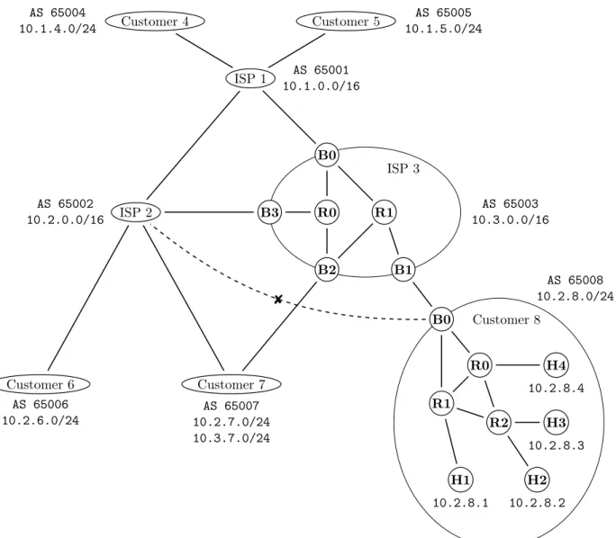
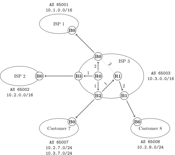
Figure 2.1 presents the infrastructure which we will be using for the design of a route aggregation model. It involves three ISPs interconnected together, each having various customers to which they are providing connectivity to the rest of the network. The prefixes allocated to a corresponding entity are given next to it. For example, ISP 2 has been allocated the prefix 10.2.0.0/16 with the possibility to sub-allocate it further, as it did for Customer 6. The inter-connected group of ISPs forms the backbone of the infrastructure and provides connectivity between the various customers. In order to be reachable in the global routing infrastructure, an end-system must have an address assigned to it; for example host H4 has been assigned address 10.2.8.4 which belongs to the prefix allocated to Customer 8. Customer 7 has been allocated prefixes 10.2.7.0/24 from ISP 2 and 10.3.7.0/24 from ISP 3 and represents a case of multi-homing through both of its providers. The internal network of Customer 8 is detailed on Figure 2.1 and represents the case of a re-homed domain which has kept its allocated prefix (a sub-prefix of 10.2.0.0/16 allocated by ISP 2) when it changed its connectivity provider to ISP 3. For any of its host to be reachable from the other customers, that host has to be assigned an IP within the prefix 10.2.8.0/24.
Destination Next-hop Hop count
10.2.8.1 R1 2
10.2.8.2 R1 3
10.2.8.3 R0 3
10.2.8.4 R0 2
Figure 2.2: Routing table of router B0 of Customer 8.
In practice, the border router B0 needs to keep track of how to reach the individual hosts within its internal network in its routing table (see Figure 2.2). With respect to the outside, it need only to advertise it is able to reach any address in the prefix 10.2.8.0/24. This means that the border router B1 of ISP 3 receives one route advertisement from router B0 of Customer 8 for prefix 10.2.8.0/24 which will result in a unique entry in its forwarding table (Figure 2.3). The forwarding table of B1 without route aggregation would contain 4 entries, for destinations 10.2.8.1 through 10.2.8.4, all pointing to C8.B0 as the next-hop. The use of route aggregation enables to merge all those entries into a single one, covering the 256 possible addresses contained in the prefix 10.2.8.0/24 allocated to Customer 8.
enti-ISP 1 AS 65001 10.1.0.0/16 ISP 2 AS 65002 10.2.0.0/16 Customer 4 AS 65004 10.1.4.0/24 Customer 5 AS 65005 10.1.5.0/24 Customer 6 AS 65006 10.2.6.0/24 Customer 7 AS 65007 10.2.7.0/24 10.3.7.0/24 ISP 3 AS 65003 10.3.0.0/16 B0 B3 B2 B1 R0 R1 Customer 8 AS 65008 10.2.8.0/24 B0 R0 R1 R2 H1 H2 H3 H4 10.2.8.1 10.2.8.2 10.2.8.3 10.2.8.4 8
Figure 2.1: High-level view of a networking infrastructure with a detailed view of the internals of ISP 3 and Customer 8. Ellipses represent the domains taking part in the RA process while circles represent end-systems or routers.
ties. For example, ISP 1 will have an alternative to reach Customer 7; a route for the prefix 10.2.0.0/16 (going through ISP 2) and another for the prefix 10.3.0.0/16 (going through ISP 3).
We will present in Chapter 3 how the interplay of the interior and exterior protocols result in the forwarding tables that are used to transmit traffic through the infrastructure in order to reach the desti-nations intended by the destination address used. We will present the way route information is exchanged and transformed as it traverses multiple domains. The route aggregation mechanism is introduced in this process along with the way routers perform the merging of multiple routes. This method can introduce reachability issues and we will illustrated some of them.
Chapter 4 will cover the theoretical foundations surrounding the constructs relevant for algebraic routing; the study of shortest-paths problems where shortest is understood in the sense of optimal. The exposition will be limited to the elements which are relevant for our needs, a more thorough and wider treatment of this vast topic can be found in [25].
In Chapter 5 we will describe how the tools and results from algebra can be used to model the metrics that are used in real-world scenarios to rank the paths that are progressively identified by routing pro-tocols throughout their execution, an aspect which is relevant for the routing perspective, but also the path-related information which somehow implements the actual paths that are found by those routing
Destination Next-hop Distance 10.1.0.0/16 R1 3 10.2.0.0/16 R1 5 10.2.8.0/24 C7.B0 3 10.3.0.0/16 R1 3
Figure 2.3: Forwarding table used by router B1 of ISP 3.
protocols, an aspect relevant from a forwarding perspective. We will relate the standard Dijkstra and Bellman-Ford algorithms to the linear recurrence equations introduced in Chapter 4 by proving that these algorithms are computing fixpoints to such equations.
The two inter-related mechanism, route aggregation and longest-match prefix, described above will be modelled within a unique construct in Chapter 6. We will first design a model of route aggregation as it is performed by external peers by removing the internal details of the domains. In this context, routers use admistrator-configured aggregation rules in order to merge routes and provide them consistently to all their neighbors. We will illustrate how re-homing and multi-homing are captured in our model. This attempt will endeavour to reduce the computation of forwarding tables to the same framework which can express the computation of shortest paths, the fixpoints to linear recurrence equations. We will conclude this chapter by showing how reachability issues can be identified by making explicit the relationship between the fixpoints obtained and the routes effectively used. The second part will cover how route aggregation as it is performed internally to a domain can be expressed. In this case, we will discuss the ability of our approach to capture the formation of forwarding loops in the produced solutions.
Chapter 3
An overview of Route Aggregation
Ever since its humble beginnings as a network connecting a dozen of hosts together, the Internet has evolved into the biggest routing infrastructure known today. In order to be able to provide connectivity to its ever-increasing number of hosts, a variety of architectural considerations have been incorporated into its inner workings. Over the decades of evolution and growth it has undergone, Autonomous Systems emerged as the top-level entities in charge of establishing and maintaining the routes to its ever-growing number of destinations.
An Autonomous System, also referred to as a domain, is a network managed by an organisation through which traffic can transit. Figure 3.1 illustrates the structure of a domain where routers are distinguished based on whether they lie at the edge of the domain (border routers), or inside it (internal routers). A domain with a single border router is a customer which only requires it to connect with its provider while a domain with multiple border routers serves as a transit domain. The establishement of routes is performed at two levels, with the interplay of two processes giving rise to the routes that are used to forward traffic. At the intra-domain level, all routers are running an Interior Gateway Protocol (IGP) in order to construct and maintain routing tables describing the best paths towards all the other routers belonging to the same domain but also to the border routers from neighboring domains directly connected to its own. At the inter-domain level, the border routers are running an Exterior Gateway Protocol (EGP) through which they can be engaged in peering sessions with each other in order to ex-change information that allows them to maintain forwarding tables describing all the best routes they know. In reaction to the route advertisements it receives, a border router can introduce or retract entries in its forwarding table to maintain connectivity in the context of a changing topology. Aside from the advertisements, border routers can be configured with static routes to originate routes to destinations. A distinction is made between internal and external peering. External peering involves border routers from distinct domains. In this case, various attributes of the routes such as the number of domains traversed to reach the destination are taken into consideration in the process by which the best routes are selected. In the case of internal peering, border routers which belong to the same domain are involved. As such, the attributes of the routes are complemented by the information contained within the routing tables to play a role in the selection of the best routes. For example, if a border router receives a route to the same destination from two different internal peers, the interior cost to reach these peers through the infrastructure may be used in the selection process.
This means that the network administrator can perform traffic engineering [3] within its domain and decide how the load is distributed across its infrastructure by choosing the policy to be applied on the links. Furthermore, the IGP used can incorporate those considerations to choose the paths based on dynamic aspects such as load, delay or reliability. To some extent, the administrator can also influence how traffic flows into the domain by the use of the MULTI_EXIT_DISC attribute or multi-homing.
Two pieces of information have to be obtained by the organisation managing a network to be able to act as an AS and participate in the global infrastructure; an AS number (ASN) and a network prefix. An ASN [47, 60] is a number which uniquely identifies an AS in the global infrastructure and is assigned by the Internet Assigned Numbers Authority (IANA)[30]. A network prefix is a set of addresses that are managed by an organisation who is allowed to either assign them to hosts within its network or allocate a subset to another organisation, typically one of its customers. At the root of this hierarchy, the IANA is in charge of managing the prefix 0.0.0.0/0 which contains all IPv4 addresses. The IANA allocates
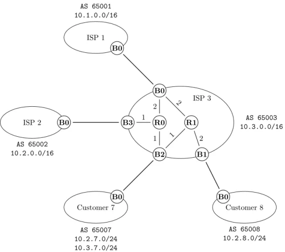
ISP 3 AS 65003 10.3.0.0/16 B0 B1 B2 B3 R0 R1 2 2 2 1 1 1
Figure 3.1: Internal structure of an Autonomous System.
subprefixes of important size (/8) to five Regional Internet Registries (RIR), each of which is tasked with the allocation for a vast geographical region1. Below the RIRs are Local Internet Registries (LIR)
which are typically Internet Service Providers (ISPs) or other organisations who assign most of the block they obtain to their customers. The AS on Figure 3.1 has been allocated ASN 65003 with the network prefix 10.3.0.0/16 which means that it can manage the IP addresses ranging from 10.3.0.0 through 10.3.255.255 as it sees fit.
The process by which a packet is handled by routers is a destination-based hop-by-hop forwarding [41]. Whenever a packet is received by a border router, a lookup is performed within its forwarding table to identify the most suitable matching entry based on the destination address. Conceptually, the next-hop represents the next domain along the way when the destination lies outside the current domain and is represented by the external peer of the next domain along the way. In the case where this peer is connected to another border router than the one who received the packet, the routing table provides the information to get the packet through the current domain to that border router. The repetition of this process by the border routers of the successive domains eventually brings the packet to its final destina-tion. Similarly, within a domain, the routers perform a process that brings the packet from the border router where it entered to the one that is connected to the external peer. The routing tables inside the domains complement the forwarding tables at the AS level in order to fully implement the routes that packets are expected to follow towards their destination.
Instead of keeping track of a route for each destination network, routers can aggregate them together when they are compatible in some way. A domain that provides connectivity to multiple customers can choose to conceal the routes to their specific network prefixes behind the one it has been allocated and take care of forwarding any packet to any of them according to the effective routes that it knows. By keeping the details of how to reach several destination to itself, a domain can advertise a route to a more general destination that covers all of the child routes, thus reducing the amount of routes that it adver-tises to its neighbors. This mechanism was originally introduced as a means to slow down the growth rate of the global forwarding table by limiting the amount of information that needs to be advertised to other domains to a strict minimum. Another issue that route aggregation mitigates is known as route flapping [59], where changes to routes in a portion of the infrastructure that is being aggregated remain concealed thus preventing unecessary processing and communications in other routers.
In this chapter, we will describe how route aggregation works. We will start by presenting what destinations represent and how they relate to hosts or networks. We will be focusing on IPv4 [45] coupled with the Classless Inter-Domain Routing (CIDR) scheme [23]. We will briefly present how an IGP constructs routing tables within a domain. The routing tables play a role in completing the information that is discovered by an EGP in order to accept only routes that are usable through its domain. The de facto standard EGP in use today is known as the Border Gateway Protocol (BGP-4). We will describe the process of route advertisement, how the best routes are selected based on their attributes and how border routers update those attributes upon exchanging their routes with their peers. We will conclude this chapter by presenting the route aggregation mechanism. The aggregation can happen in multiple places and under various conditions. Our focus will be on the aggregation mechanism at the BGP-4
level between external peers and within a simplified IGP. The separation between the forwarding table and the advertised routes is the means by which it is implemented. Each border router maintains the effective routes that it uses for forwarding purposes and the set of routes that it advertises to its peers separate. By advertising aggregate routes but forwarding according to its effective routes, the border routers can maintain reachability towards destinations while helping its external peers reduce the size of their forwarding tables. The specifications of EGP and IGP leaves some freedom for the implementation with the consequence that routers from different manufacturers behave in different ways. From the perspective of BGP, the problem lies in how the attributes of an aggregate route are obtained from the child routes. In [36], Le & al. covered many subtle differences observed in hardware from different manufacturers. We will conclude this chapter by looking at how the default mechanism in Cisco routers can result in reachability issues.
3.1
Addressing schemes
An addressing scheme works by attaching some information to physical vertices that allows them to be reachable through the construction of routing and forwarding tables. In [45], IPv4 addresses are 32-bit identifiers that are used to label packets so that routers can use their tables to forward traffic towards the hosts using them. Other schemes have been proposed over the years to provide more features. IPv6 [15] was introduced to expand the size of the address space by using 128 bits identifiers. An ongoing effort is the Locator-Identifier Separation Protocol [50] which separates the location of a router from its identifica-tion, two functionalities currently conflated in IP addresses. Another one is the Compact Routing [34, 58] which studies how routing schemes capture a trade-off between the size of the routing tables produced with respect to the stretch of the routes they encode. The stretch refers to a factor that exists between the route found and the shortest one that exists.
In this work, we will be considering the coupling of IPv4 with the CIDR addressing scheme. A CIDR prefix is a concise representation of a range of addresses which can be expressed in a binary format. In the case of IPv4, both IP addresses and network masks are encoded as 32-bit words; for example the prefix 10.1.4.0/24 can be represented as follows
10.1.4.0 00001010000000010000010000000000 (address) {24 11111111111111111111111100000000 (mask) The idea that a given CIDR prefix is a subprefix of another is central to the aggregation mechanism; whenever an AS is managing a prefix and receives a route advertisement for a prefix covered by its own, the covering prefix should be advertised instead. Consider the following two prefixes
10.1.0.0 00001010.00000001.00000000.00000000 {16 11111111.11111111.00000000.00000000
10.1.5.0 00001010.00000001.00000101.00000000 {24 11111111.11111111.11111111.00000000
The two prefixes 10.1.4.0/24 and 10.1.5.0/24 are subprefixes of 10.1.0.0/16 but are disjoint with each other. Given two prefixes pa1, m1q and pa2, m2q, we can define the subprefix relation Ď by
pa1, m1q Ď pa2, m2q fi m2ď m1 ^ a1 & m2“ a2 & m2 (3.1)
where the & operator stands for the pointwise combination of the two operands by the binary AND operation (a.k.a. bitwise AND [31]). In other words, a prefix is a subprefix of another if-and-only-if the length of the mask of the latter is greater than that of the former and the bits covered by the mask of the latter are identical in both prefixes.
3.2
Interior Gateway Protocol
Despite the diversity of routing protocols designed to run within a domain, all share the common goal of establishing paths between the routers within its boundaries along with the external peers connected to its border routers. The inclusion of the external peers in this process is due to the fact that they are used
ISP 1 AS 65001 10.1.0.0/16 B0 ISP 2 AS 65002 10.2.0.0/16 B0 ISP 3 AS 65003 10.3.0.0/16 B0 B1 B2 B3 R0 R1 2 2 2 1 1 1 Customer 7 AS 65007 10.2.7.0/24 10.3.7.0/24 B0 Customer 8 AS 65008 10.2.8.0/24 B0
Figure 3.2: Internal structure of ISP 3 with the cost metric.
as the next-hops for route advertisements at the EGP level. Once the decision has to be made as to which route to accept for a destination, the external peer associated with it has to be reachable for the route to be usable by a border router. In practice there are interactions from EGP to IGP, with the possibility for route advertisements to result in the insertion of entries into the routing tables of internal routers regarding the associated destinations. For the sake of clarity, we choose to separate the two concerns but these interactions will be discussed once we have covered EGP. The purpose of this section is to present how an IGP works to produce and maintain the routing tables throughout its execution. We will start by discussing the algorithms underlying the two approaches to routing protocols; Dijkstra’s Algorithm[16] for the link-state approach and Bellman-Ford’s Algorithm[5] for the distance-vectoring method. We will illustrate a run of both algorithms in ISP 3 as shown on Figure 3.2. In a real-world network, the routers are assigned IP addresses but we omit them for conciseness. The problems that can arise from the use of one or the other will be exposed and discussed. The cost associated with the links are attached to them on the graph and each undirected link is bidirectional. We use undirected links as shorthand for two directed arcs going in both directions with identical costs. In some contexts, it is common for the label to be different for each direction, with complex metrics typically exhibiting an asymmetry in the labelling of the graph. The process by which the routing tables are derived from the solutions produced by those algorithms will be presented along with the forwarding mechanism. For more details about a specific IGP, we point the reader to the corresponding specifications and technical literature.
3.2.1
Link-State Routing Protocol (LSRP)
All the routing protocols falling in the link-state class somehow rely on Dijkstra’s Algorithm [16, 11], presented here as Algorithm 1, for the computation of a shortest-path tree from which the routing table can be derived. The process that link-state protocols use is structured in three phases; link-state flooding to allow all routers to build a complete representation of the network’s topology, execution of Dijkstra’s Algorithm to produce a shortest-path tree and finally construction of the routing table based on that shortest-path tree. This algorithm can be easily modified to produce the contents of the routing table
di-rectly. In the remainder of this section, the words router and vertex are considered to be synonymous. A prerequisite for the execution of Dijkstra’s Algorithm is a complete knowledge of the connectivity within the network by the source router running it. The link-state flooding phase is used to disseminate the topological information from every router to every other. Each entry of the resulting link-state database, Ai,j, encodes the cost of the direct link that goes from vertexi to vertex j. A special value 8 is used to
denote the absence of a direct link between the corresponding vertices. At the beginning of the execu-tion, all destinationsd P V are considered unreachable except the source, which is the router running the algorithm. The termination of the execution is guaranteed by the fact that a set of relaxed vertices R increases in size at every iteration by inclusion of a relaxation vertex selected at each iteration. Because the source router has a complete knowledge of the topology, it can compare its current knowledge of the cost (ω) towards the direct neighbors of the relaxation vertex q with the current knowledge of the cost to q before using the direct link from q to its direct neighbors. The strategy to choose the relaxation vertex is to pick the closest unrelaxed vertex, a greedy choice that does not prevent the final value of ω for all destinations to be optimal. It is possible to demonstrate that the cost associated with the relaxed vertices is minimal and will not be updated by any later iteration, which is why only unrelaxed destinations are considered on Line (9).
Algorithm 1 Dijkstra’s Algorithm for the cost metric
1: for alld P V do 2: ωrds Ð 8 3: end for 4: ωrss Ð 0 5: R Ð ∅ 6: while R ‰ V do
7: pickq P V ´ R such that @ q1 P V ´ R : ωrqs ď ωrq1s
8: R Ð R Y tqu 9: for alld P V ´ R do 10: if ωrds ą ωrqs ` Aq,dthen 11: ωrds Ð ωrqs ` Aq,d 12: end if 13: end for 14: end while
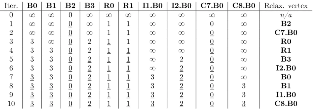
The link-state database for Figure 3.2 is given as Table 3.3 with all the internal links. As a comple-ment, the links towards external peers are included with a cost of 0 associated with them. The reason we omit the direction coming from the external peers of the other domains is simply because they do not participate in the IGP within ISP 3 and as such do not provide link-states for their connectivity. In this example, we associate the cost0 to the external links. This means that the cost to reach an external peer will be given directly by the cost of traversing the domain to the border router it is connected to. When considering the interaction between IGP and EGP, the metric for the external link is not the same as the internal metric. In the presence of multiple independent connections between two domains, the net-work administrator might decide either to favour the internal cost over the external metric, an approach known as hot-potato routing [56, 57], in order to get the packets faster out of its network. In contrast, cold-potato routing attempts to find the most interesting external route with the potential consequence of keeping packets longer within the network.
A run of Algorithm 1 at router B2 is given on Figure 3.4. Each line gives the iteration number of the main loop at Line (6), the costs to reach all other routers produced by that iteration along with the relaxation vertex. Once a vertex has been relaxed, its distance is underlined. The first line describes the state after initialization is performed. Due to the fact that external peers are not connected to any further vertices, the iterations that consider them as relaxation vertices do not change the costs known towards other routers. Because of the initialization, the first relaxation vertex is always the source since it has the lowest value of 0. The third iteration involves a non-deterministic situation where both R0 and R1 are candidates for relaxation.
We will prove in Chapter 5 that the choice of either candidate results in the same final answer in general. In this case the relaxation of R0 followed by R1 brings us to a makes vertex B0 the only
Source Destination Cost R0 B0 2 R0 B3 1 R0 B2 1 R1 B0 2 R1 B2 1 R1 B1 2 B0 R0 2 B0 R1 2 B3 R0 1 B2 R0 1 B2 R1 1 B1 R1 2 B0 I1.B0 0 B3 I2.B0 0 B2 C7.B0 0 B1 C8.B0 0
Figure 3.3: Link-state database for ISP 3.
Iter. B0 B1 B2 B3 R0 R1 I1.B0 I2.B0 C7.B0 C8.B0 Relax. vertex
0 8 8 0 8 8 8 8 8 8 8 n/a 1 8 8 0 8 1 1 8 8 0 8 B2 2 8 8 0 8 1 1 8 8 0 8 C7.B0 3 3 8 0 2 1 1 8 8 0 8 R0 4 3 3 0 2 1 1 8 8 0 8 R1 5 3 3 0 2 1 1 8 2 0 8 B3 6 3 3 0 2 1 1 8 2 0 8 I2.B0 7 3 3 0 2 1 1 3 2 0 8 B0 8 3 3 0 2 1 1 3 2 0 3 B1 9 3 3 0 2 1 1 3 2 0 3 I1.B0 10 3 3 0 2 1 1 3 2 0 3 C8.B0
Figure 3.4: Run of Algorithm 1 with router B2 as the source.
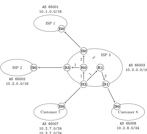
candidate for relaxation for Iteration 6. Iteration 7 through 9 involve several candidates for relaxation, no matter the order in which they are selected, the costs obtained after the final iteration will be the same with the only difference being the successive sets of candidates possible. The complete shortest-path tree resulting from running Algorithm 1 at router B2 is given on Figure 3.5. The use of oriented links comes from the fact that those indicate the direction in which the path is going.
The greedy strategy to pick the closest unrelaxed vertex for relaxation implies that onlyn iterations of the main loop from Line (6) are required. The overal complexity of the algorithm depends on how the selection of the relaxation vertex at Line (7) is performed. The use of Fibonacci Heaps [22] to manage the set of unrelaxed vertices results in a complexity on the order of pm ` n logpnqq where n is the number of vertices andm the number of arcs.
In order to be useful for the construction of a routing table which associates a next-hop to every destination, the algorithm requires a minor modification to the solution it produces by storing structural information about the shortest-path tree itself. One way this can be achieved is by keeping track of the relaxation vertex [11] through which the last value of the cost was updated by Line (11). In this case the relaxation vertex represents the predecessor of the destination along the way. The inclusion of the predecessor vertex means that the output of the algorithm is no longer unique. There are two paths with the best cost 3 going from B2 to B0, B2 Ñ R0 Ñ B0 and B2 Ñ R1 Ñ B0. Depending on the order in which these two vertices are relaxed, the resulting shortest-path tree will be different. The resulting vectors, ω for the costs and π for the predecessors are given below and can be matched with the tree presented on Figure 3.5. A hyphen ´ is a generic way to represent that the predecessor is the source router. Another way to phrase this is that all destinations from the π vector with a hyphen are direct neighbors of the source router that executed the algorithm.
ISP 1 AS 65001 10.1.0.0/16 B0 ISP 2 AS 65002 10.2.0.0/16 B0 ISP 3 AS 65003 10.3.0.0/16 B0 B1 B2 B3 R0 R1 2 2 2 1 1 1 Customer 7 AS 65007 10.2.7.0/24 10.3.7.0/24 B0 Customer 8 AS 65008 10.2.8.0/24 B0
Figure 3.5: The shortest-path tree rooted at vertex B2.
B0 B1 B2 B3 R0 R1 I1.B0 I2.B0 C7.B0 C8.B0
ω 3 3 0 2 1 1 3 2 0 3
π R0 R1 ´ R0 ´ ´ B0 B3 ´ B1
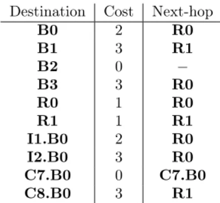
Figure 3.6: Costs and predecessors obtained at the source router B2. A hyphen ´ denotes the fact that the corresponding destinations are directly connected to the source.
Destination Cost Next-hop B0 2 R0 B1 3 R1 B2 0 ´ B3 3 R0 R0 1 R0 R1 1 R1 I1.B0 2 R0 I2.B0 3 R0 C7.B0 0 C7.B0 C8.B0 3 R1
Figure 3.7: Routing table of B2 obtained from the output of Algorithm 1 augmented with predecessors. B0 B1 B2 B3 R0 R1 I1.B0 I2.B0 C7.B0 C8.B0
ω 2 4 1 1 0 2 2 4 1 1
π ´ R1 ´ ´ ´ B2 B0 B3 B2 B1
Figure 3.8: Costs and predecessors obtained at the source router R0.
done by a recursive lookup of the predecessors until a hyphen is reached. For example, to identify the next-hop for destination I1.B0, the sequence of predecessors will be B0, R0, ´, which indicates that R0 is the next-hop to be used when attempting to reach I1.B0. By applying this method for all destinations, the routing table for B2 can be obtained with the corresponding costs associated with the destinations. Each router within the network using a LSRP will produce its own routing table independently of the other routers. In the context of next-hop forwarding, this brings the question of consistency across routers. Figure 3.8 presents the vectorsω and π obtained by router R0 running Algorithm 1. Given that B2 computes its shortest-path tree independently of R0 without any form of coordination, one could wonder how the path identified by R0 (R0 Ñ B0 Ñ I1.B0) is consistent with the one computed by B2 (B2 Ñ R0 Ñ B0 Ñ I1.B0). The possibility for inconsistency was identified by Sobrinho & Griffin in [54] where they narrowed down the root of the problem to an algebraic property of the metric being used. They showed that when a complex metric involving bandwidth with a tie-breaking on the distance for the selection of best paths was used, routers could disagree on the best path from their perspective towards a destination. In the worst case, this can result in routing loops that are distributed across the routing tables of several routers. Dijkstra’s Algorithm has already been the object of several generalizations and applications [33, 43].
3.2.2
Distance-Vectoring Routing Protocol (DVRP)
The second class of routing protocols is based on a distance-vectoring method. In contrast with the link-state approach, the routers running a DVRP work by exchanging information about the paths they identified towards destinations. The internal behavior of DVRP can be summarized as 3 phases; reception of path information provided by a direct neighbor with a recomputation of its associated cost, selection between the path by comparing its updated cost with the one currently known towards the corresponding destination and sending of updates to the direct neighbors. We delay the presentation of any pseudo-code for the Bellman-Ford’s Algorithm [5] until Chapter 5.
The only topological information that a router needs to maintain is the cost associated with the outbound links towards its direct neighbors. This adjacency information corresponds to the row of the link-state database with the source set to the current router. In the initial state, only the distances to the direct neighbors are known from the adjacency information. This provides the router with its initial routing table. The path information is represented as tuples that associate a destination with a cost. Upon receiving path information that associates a destinationd with a cost c from a neighbor q, the cost is updated to Ai,q` c. The resulting cost is compared with the one for the best path currently known
to reach d and the one with the lowest value is kept. In the event where the neighbor which provided the new path is identical to the one that provided the path currently in the routing table, the new path replaces it in order to keep the most recent information. If the best path changes due to this operation, the router must announce this update to its direct neighbors as a means to inform them its perspective
ISP 1 AS 65001 10.1.0.0/16 B0 ISP 2 AS 65002 10.2.0.0/16 B0 ISP 3 AS 65003 10.3.0.0/16 B0 B1 B2 B3 R0 R1 2 2 2 1 1 1 Customer 7 AS 65007 10.2.7.0/24 10.3.7.0/24 B0 Customer 8 AS 65008 10.2.8.0/24 B0
Destination Distance Next-hop B0
R0 2 R0
R1 2 R1
I1.B0 0 I1.B0
Destination Distance Next-hop
B1 R1 2 R1
C8.B0 0 C8.B0
Destination Distance Next-hop B2
R0 1 R0
R1 1 R1
C7.B0 0 C7.B0
Destination Distance Next-hop
B3 R0 1 R0
I2.B0 0 I2.B0
Destination Distance Next-hop R0
B0 2 B0
B2 1 B2
B3 1 B3
Destination Distance Next-hop R1
B0 2 B0
B1 2 B1
B2 1 B2
Figure 3.10: Initial routing tables corresponding to the adjacency information for each router within the boundaries of ISP 3.
on how to reachd has changed. Note that a router need not perform this update everytime for every new path information received. It can accumulate the path information over a certain interval of time before running the process over the resulting collection.
Any changes to the topology affect the local routing table whose information is then diffused through the infrastructure without the need to flood any link-state change to all routers. This has the consequence that a DVRP can adapt faster to topological changes. In contrast with a LSRP, the paths used through-out the infrastructure are constructed backward, starting from the destinations and flowing back to other routers. The next-hop consistency question that was raised at the end of the previous section is solved by the fact that the selection process is based solely on the connectivity that neighbors are announcing and not an assumption on the choices made by other routers along the path. This also allows the routing tables to be directly constructed without the use of an intermediary shortest-path tree. Whenever the selection process picks the best path towards a destination, the next-hop is already known as the neighbor who originally provided that path.
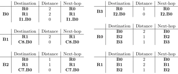
The adjacency information for the entire network is provided in the form of the initial routing tables on Figure 3.10 where the distance is given for each router and destination. We assume that the external peers connected to the border routers have an associated distance of 0. Unlike LSRP, it is not possible to focus on the computation being performed by one vertex since the path information is progressively constructed and distributed by all the vertices. For this reason, we will illustrate a run of the algorithm by showing the routing tables of each router of ISP 3. The interleaving in which the routing table updates are exchanged allows for a consequent number of possible executions. For this reason, we choose to illustrate the execution in lockstep by considering that all the routing tables are computed in a synchronized way. The routing tables at one iteration are obtained independently from the routing tables of the previous iteration. The initial routing tables at each router are listed on Figure 3.10 where for each destination, the distance and next-top are given.
During the first iteration, router B2 will receive the routing tables of routers R0 and R1. The col-lection of paths with updated costs are listed on Figure 3.11. They are obtained by taking the entries of the routing table of R0 (resp. R1) and adding the cost from B2 to R0 (resp. R1) to the cost of each entry. Figure 3.12 gives the new routing table for router B2, which is obtained by picking for each destina-tion the path with the least cost among those from the collecdestina-tion of updated paths on Figure 3.11 and the previous routing table on Figure 3.10. The paths for destination B2 are discarded due to the implicit path with cost0 that always exists between a router and itself. For destination B0, the paths through R0 and R1 both have the same cost so either of them could serve as the next-hop. The origin of each path information is used as the next-hop in the routing table.
The reachability has increased for all routers after one iteration, with destinations B0, B3 and B1 now reachable through R0 and R1 from B2. Through the progressive exchange of updates to their
Destination Cost From B0 3 R0 B3 2 R0 B2 2 R0 B0 3 R1 B2 2 R1 B1 3 R1
Figure 3.11: Collection of paths at router B2 during the first iteration.
Destination Distance Next-hop
B0 B1 4 R1 B2 3 R0 B3 3 R0 R0 2 R0 R1 2 R1 I1.B0 0 I1.B0
Destination Distance Next-hop
B3
B0 3 R0
B2 2 R0
R0 1 R0
I2.B0 0 I2.B0
Destination Distance Next-hop
B2 B0 3 R0 B1 3 R1 B3 2 R0 R0 1 R0 R1 1 R1 C7.B0 0 C7.B0
Destination Distance Next-hop
B1
B0 4 R1
B2 3 R1
R1 2 R1
C8.B0 0 C8.B0
Destination Distance Next-hop
R0 B0 2 B0 B2 1 B2 B3 1 B3 R1 2 B2 I1.B0 2 B0 I2.B0 1 B3 C7.B0 1 B2
Destination Distance Next-hop
R1 B0 2 B0 B2 1 B2 R0 2 B2 I1.B0 2 B0 C7.B0 1 B2 C8.B0 2 B1
Destination Distance Next-hop B0 I1.B0 0 I1.B0 I2.B0 3 R0 B3 3 R0 B2 3 R0 B1 4 R1 C7.B0 3 R0 C8.B0 4 R1 R0 2 R0 R1 2 R1
Destination Distance Next-hop
B3 I1.B0 3 R0 I2.B0 0 B1 B0 3 R0 B2 2 R0 B1 5 R0 C7.B0 2 R0 C8.B0 5 R0 R0 1 R0 R1 3 R0
Destination Distance Next-hop
B2 I1.B0 3 R0 I2.B0 2 R0 B0 3 R0 B3 2 R0 B1 3 R1 C7.B0 0 C7.B0 C8.B0 3 R1 R0 1 R0 R1 1 R1
Destination Distance Next-hop
B1 I1.B0 4 R1 I2.B0 5 R1 B0 4 R1 B3 5 R1 B2 3 R1 C7.B0 3 R1 C8.B0 0 C8.B0 R0 4 R1 R1 2 R1
Destination Distance Next-hop
R0 I1.B0 2 B0 I2.B0 1 B3 B0 2 B0 B3 1 B3 B2 1 B2 B1 4 B2 C7.B0 1 B2 C8.B0 4 B2 R1 2 B2
Destination Distance Next-hop
R1 I1.B0 2 B0 I2.B0 3 B2 B0 2 B0 B3 3 B2 B2 1 B2 B1 2 B1 C7.B0 1 B2 C8.B0 2 B1 R0 2 B2
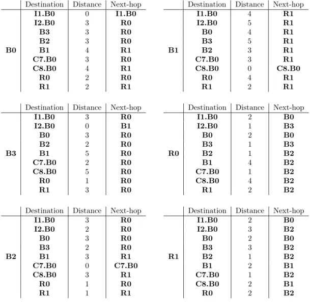
Figure 3.13: Routing tables after convergence.
routing tables, the routers eventually converge to a set of routing tables which is given on Figure 3.13.
The distance-vectoring approach suffers from problems of its own that a DVRP has to address to guarantee proper working. Due to the dynamic aspects involved in a running network, links are subject to failure. A possible consequence of such a failure is the count-to-infinity problem [35].
It is commonplace to discuss LSRP and DVRP in terms of communication overhead, convergence speed and adaptability to dynamic changes of the topology. In [19], we demonstrated that the two ap-proaches can disagree on which are the best paths in a given network labelled by means of a given metric. Equal-Cost Multi-Path (ECMP) is a method by which a routing protocol confronted with multiple equally good paths towards a destination keeps them and applies a load-balancing algorithm when forwarding occurs. By modelling ECMP within an algebraic formalism [25, 27], we were able to identify a sufficient condition for both classes of routing protocols to agree on all best paths towards all destinations. For example, under ECMP, two paths connecting B2 to B0 with weight 3 would end up in the routing table, B2 Ñ R0 Ñ B0 and B2 Ñ R1 Ñ B0, and would be usable for forwarding.
Various techniques exist to allow several IGP to run side by side within the same infrastructure, contributing to the routing tables that are obtained (Administrative Distance) or exchanging the routes they identified among each other (Route Redistribution).
3.2.3
Open Shortest Path First (OSPF)
OSPF [40, 10] is a link-state protocol that uses a cost for making its decisions. This cost is defined as a dimensionless, lower-is-better metric. Whenever relaxation occurs, the cost of the path to the relaxation vertex is added to the one of the link to its neighbor to produce the total cost. The routing tables support CIDR notation and use the Longest-Match Prefix rule for forwarding. Under this rule, the destination of a packet is matched against that of each entry of the forwarding table. The entry whose destination prefix matches most bits of the destination address is used to forward the packet. This enables the route information learned at the edge of the AS to be injected into the routing tables as a means to implement the routes passing through the AS. In order to reduce the convergence time, communication overhead and increase stability of the routing tables across the domain, OSPF introduces a mechanism to divide the internal network of the AS into areas all connected to a special backbone area. There are four types of routers in OSPF terminology. An AS Boundary Router (ASBR) is a router that is communicating with routers belonging to another AS, exchanging the route information and injecting the route information into the AS. An Area Border Router (ABR) lies at the boundaries of multiple areas and runs an instance of the link-state algorithm for each area it has an interface in. It also takes care of summarizing the path information pertaining to the destinations that are reachable through the area it sits in before sending them to the backbone for redistribution into the other areas. A Backbone Router is a router with an interface connected to the backbone and an Internal Router has all its interface in the same area. In the event where multiple paths with identical least cost are identified, OSPF is designed to use Equal-Cost Multi-Path (ECMP).
3.2.4
Routing Information Protocol Version 2 (RIPv2)
RIPv2 [37] is a simple distance-vectoring protocol that relies on a classical concept of distance to reach destinations. The routing table support CIDR notation and LMP, allowing for the route information learned by border routers to be injected into the AS to insert additionnal forwarding entries. The path information stored in the routing table is managed by a garbage collector that cleans up the entries that are not refreshed by the neighbor who originally announced them. Due to the typical network size envisionned and as a means to reduce the time routers spend counting-to-infinity, the distance 16 is used to denote an unreachable destination. A route can also be retracted from the routing table by having the neighbor who originated it send an update for that destination with a distance of16. Routing loops are prevented by the use of two mechanisms; split horizon and poisoned reverse. Under the split horizon, the routes discovered through a neighbor are not announced back to it. When poisoned reverse is used, the router is allowed to announce the route back to the neighbor who advertised it after setting its associated distance to 16. Whenever a routing loop forms between two neighbors, poisoned reverse forces the removal of both routes.
3.2.5
Enhanced Interior Gateway Routing Protocol (EIGRP)
EIGRP [46] is a hybrid distance-vectoring protocol that was originally developed by Cisco but later turned into an open standard. It uses a custom algorithm known as the Diffused Update Algorithm (DUAL) and a composite metric that includes both static and dynamic aspects; the minimal bandwidth along the path, the load describing how saturated the path is, the delay from the router to the destination and the reliability of the path. The four components are combined according to
„ K1ˆ bandwidth `K2 ˆ bandwidth p256 ´ loadq ` K3ˆ delay ˆ K5 reliability ` K4
where each factorK1throughK5can be set to alter the metric in subtle ways. It relies on a sufficient
condition to guarantee only loop-free paths are selected. The freedom provided by the use of these factors enables network administrators to design their own metric from a restricted space of possibilities.
3.3
Exterior Gateway Protocol
The Border Gateway Protocol (BGP-4) has become the de facto standard for managing the exchange of connectivity information between ASes. RFC4271[47] specifies, among other things, the structure of an advertisement, the way in which it they are exchanged, the rules for selecting the best routes that end up in the forwarding table (the import policy) and to which peers they are advertised (the export
policy). Concisely, BGP-4 can be described as a path-vectoring protocol for disseminating connectiv-ity information towards destinations represented by IPv4 network prefixes with the goal of constructing destination-based forwarding tables. A path-vectoring protocol constructs routes in a similar way to the way a DVRP does in the sense that participating routers learn routes from their peers and select the best ones among those after updating their attributes. In this section, we will give a detailed description of how BGP-4 constructs the forwarding tables based on its configuration. In order to connect with other Autonomous Systems, an AS uses special routers at the edge of its network called BGP speakers. These routers take care of exchanging route information with each other so that forwarding tables can be maintained up to date across ASes. The BGP speakers at the edge of two different ASes can be connected through the BGP-4 protocol (external peering) but it also allows BGP speakers from a given AS to com-municate with each other (internal peering). Depending on the type of peering, the rules for handling route advertisement differ slightly. We will start by describing the attributes of routes manipulated by BGP speakers. We will then present the structure of the Decision Process that picks the best routes out of an input set along with the conditions that those routes must satisfy. We will end this section by presenting examples where forwarding loops can arise due to misconfiguration. The infrastructure on Figure 3.14 will be used throughout this section to illustrate the main cases where aggregation occurs. It involves three interconnected transit ISPs along with five Customers. The network prefixes allocated to each AS are given in CIDR notation and the AS Numbers are included as well. The example is designed to include three typical scenarios that we wish to cover. We will illustrate throughout this section how these scenarios work under the regime of route advertisement handling followed by BGP-4.
Customers 4 and 5 are both using subprefixes of their provider ISP 1. As such, they fall under the typical case where route aggregation occurs as a means to merge route advertisements when they pertain to destinations that are covered by the prefix allocated to the AS.
Customer 7 will allow us to illustrate a case of multi-homing, whereby a physical network is reach-able through two independent prefixes provided by two distinct providers. This enreach-ables the customer to remain reachable when one of its providers is experiencing technical issues with its connectivity. In the event where ISP 2 encounters problems with its infrastructure, all traffic bound for 10.2.6.0/24 will be dropped, effectively rendering Customer 6 completely unreachable. Similarly, the traffic bound for 10.2.7.0/24 will meet the same fate, unlike the one for 10.3.7.0/24 which will be properly delivered. While this situation is undesirable, its occurence is beyond the reach of customers who can still remain partially reachable if they use multi-homing.
Finally, Customer 8 represents a re-homed network. The relationships between providers and cus-tomers are commercially-driven. As such, it is possible that a customer decides to resign from a provider to subscribe to another one. In this case, Customer 8 used to obtain its connectivity through ISP 2 but decided to switch to ISP 3. In order to avoid the need to change its network prefix and renumber all its hosts, Customer 8 was allowed to keep the prefix that was allocated by ISP 2.
Note that an alternative exists for the implementation of multi-homing and re-homing in terms of the type of addresses used [1]. Provider-Independent addresses have the specificity that they do not belong to any prefix allocated to domains and as such cannot undergo any aggregation at all unlike Provider-Aggregatable addresses. Provider-Independent addresses are scarce in number due to their inability to be aggregated. If their number was to grow, it would impact the size of forwarding tables across the global infrastructure and hinder the ability of route aggregation to maintain them small. We assume here the use of Provider-Aggregatable addresses.
3.3.1
Route information
The main object manipulated by BGP-4 are routes. A route describes the association of a destination, represented by a network prefix called the Network Reachability Layer Information (NLRI), together with a set of attributes. RFC4271 defines seven attributes that are categorized as either mandatory or discretionary. Mandatory attributes must always be present in route advertisements while discretionary attributes can be omitted. Table 3.15 gives the list of those attributes along with their category. The attribute LOCAL_PREF is particular in the sense that it only has meaning in the context of one domain. Whenever a route advertisement is received at a border router of a domain, a preference for that route is computed. This preference is then carried over in subsequent advertisements of that route to the internal peers of the border router who do not recompute it. We will now detail the meaning of the mandatory
ISP 1 AS 65001 10.1.0.0/16 ISP 2 AS 65002 10.2.0.0/16 ISP 3 AS 65003 10.3.0.0/16 Customer 4 AS 65004 10.1.4.0/24 Customer 5 AS 65005 10.1.5.0/24 Customer 6 AS 65006 10.2.6.0/24 Customer 7 AS 65007 10.2.7.0/24 10.3.7.0/24 Customer 8 AS 65008 10.2.8.0/24
Figure 3.14: High-level view of a networking infrastructure describing prefix allocation. Attribute Category
ORIGIN mandatory AS_PATH mandatory NEXT_HOP mandatory MULTI_EXIT_DISC discretionary
LOCAL_PREF only internal ATOMIC_AGGREGATE discretionary AGGREGATOR discretionary
Figure 3.15: List of attributes by category and scope.
attributes and go succinctly over the discretionary ones.
The ORIGIN is an attribute that describes the means through which the route information was pro-duced. The information can either be generated from within an AS (IGP) which injects the route into BGP or discovered through the Exterior Gateway Protocol (EGP). This value literally refers to a protocol described in [49]. Another possibility is that the route was produced by the aggregation of several routes or obtained through redistribution from another protocol in which case its value is INCOMPLETE. Under route aggregation, if any child route has a value of INCOMPLETE for this attribute, the ORIGIN of the aggregate route becomes INCOMPLETE. Otherwise, if any child route has a value of EGP, the ORIGIN for the aggregate route becomes EGP. Otherwise it has the value IGP.
The AS_PATH is used to encode the domains that were traversed by the route advertisement. A route is originated by an AS through advertisement to its neighbors. Those neighbors run the selection process and potentially extend and advertise the route further, carrying over the AS Numbers that were traversed by the route information. This attribute is made of path segments which can be either an AS_SET or an AS_SEQUENCE. An AS_SET is an unordered list of ASN that appears in the context of aggregation and will be discussed later. An AS_SEQUENCE is an ordered list of ASN that were traversed by the route information. Whenever a border router advertises a route to an external peer, it must prepend the ASN of its domain at the beginning of the first AS_SEQUENCE of the AS_PATH.
The NEXT_HOP field encodes the IPv4 address of the peer through which the destination is reachable. When the route information is exchanged between external peers, this attribute should be set to the address that is used to establish the BGP connection. For internal peering, the border router should not alter this attribute. The forwarding process requires the introduction of a distinction between the NEXT_HOP and the immediate next-hop. The immediate next-hop describes the internal router that should
be used as a next-hop to reach the NEXT_HOP. Consider the example we gave on Figure 3.5 when discussing LSRP and suppose that router B2 receives a packet from C7.B0 that is bound towards an address in the network 10.1.0.0/16. At the EGP level, the only possible route towards that destination has I1.B0 as its NEXT_HOP. By looking up its routing table, B2 can identify the immediate next-hop as R0 and forward the packet to it. When the NEXT_HOP of multiple routes to be aggregated are identical, it is used for the aggregate route. Otherwise the NEXT_HOP is set to the aggregating router address.
MULTI_EXIT_DISC is used whenever multiple external peering connections exist between two ASes. This metric allows to put emphasis on which external link should be favoured when several routes for inbound traffic exist through the same neighboring AS. This attribute enables a domain with multiple entry points from another domain to indicate which one should be favoured with respect to a given des-tination. In other word, this provides the network administrator with a limited ability to influence how neighboring domains send their traffic into its domain. Routes with different MULTI_EXIT_DISC values cannot be aggregated.
The LOCAL_PREF is an important metric that plays a role in the first stage of the selection of routes within the network of an AS. The first phase of the Decision Process that selects the best routes computes the preference that is given to a route based on its attributes. A typical way this is achieved is by having a configured value set for each neighboring AS which is then used as the preference for the routes provided by each AS. As the route is advertised to internal peers, the LOCAL_PREF is included in this attribute and used directly by the Decision Process of those peers.
ATOMIC_AGGREGATE is used to mark a route that was obtained by aggregating several routes. It denotes the fact that some information was removed from the AS_PATH attribute that describes the aggregated routes.
AGGREGATOR is an attribute that encodes the ASN and the IP address of the border router that per-formed the aggregation resulting in the route it is associated to. Upon aggregation, the value of this attribute must be replaced by the information identifying the aggregating router.
In the remainder of this section, we will only focus on the three mandatory attributes along with LOCAL_PREF. The rules according to which those attributes are changed throughout the Decision Process will be presented as we describe its inner workings.
3.3.2
Anatomy of a BGP Speaker
From a high-level perspective, a BGP Speaker uses three sets internally as part of its execution; an input set, a set of effective routes and a set of advertised routes. The input set of routes is used to collect the route advertisements received from peers. This set is subject to a unicity constraint on the NLRI attribute and the peer that advertised the route. Whenever a new route for an existing NLRI is received from a peer, the old route from that peer is replaced. The route advertisements are implemented by means of UPDATE messages which encode path attributes together with a set of NLRI. This allows the grouping within one UPDATE of several routes that share all their attributes. Alternatively, those messages can contain information regarding routes which were withdrawn by the peer from its forwarding table. In the event of a disconnection of a BGP session with a peer, the routes received from that peer are removed from the input set to reflect the fact that its state is no longer known and the routes that it used should not be considered for the selection phase.
Any change to the input set triggers a run of the Decision Process that performs the selection of the best routes and their subsequent advertisement. This process is structured in three phases that run in sequence. Phase I is a preprocessing applied to the contents of the input set to establish the degree of preference for each route. Phase II constitutes the core of the selection process by which the BGP speaker establishes the changes that must be applied to its set of effective routes. Phase III takes care of popu-lating the set of advertised routes to generate the new route advertisements for dissemination to the peers. The calculation of the degree of preference assigns a preference to each route in the input set. The routes that are received from internal peers already carry the LOCAL_PREF attribute which removes the need to perform this computation. While the specifics of how this computation produces the preference are left to the implementation, the only restriction is that it cannot rely on the existence or non-existence of other routes or on the attributes of other routes. It is possible that the outcome of this calculation is