HAL Id: hal-01353715
https://hal-mines-paristech.archives-ouvertes.fr/hal-01353715
Submitted on 12 Aug 2016HAL is a multi-disciplinary open access archive for the deposit and dissemination of sci-entific research documents, whether they are pub-lished or not. The documents may come from teaching and research institutions in France or abroad, or from public or private research centers.
L’archive ouverte pluridisciplinaire HAL, est destinée au dépôt et à la diffusion de documents scientifiques de niveau recherche, publiés ou non, émanant des établissements d’enseignement et de recherche français ou étrangers, des laboratoires publics ou privés.
Dendrite growth morphologies in rapidly solidified
Al-4.5wt.%Cu droplets
Marie Bedel, Guillaume Reinhart, Abdoul-Aziz Bogno, Hong-Thinh Nguyen,
Elodie Boller, Charles-André Gandin, Hani Henein
To cite this version:
Marie Bedel, Guillaume Reinhart, Abdoul-Aziz Bogno, Hong-Thinh Nguyen, Elodie Boller, et al.. Dendrite growth morphologies in rapidly solidified Al-4.5wt.%Cu droplets. 4th International Confer-ence on Advances in Solidification Processes (ICASP-4), Jul 2014, Windsor, UK, United Kingdom. pp.012055, �10.1088/1757-899X/117/1/012055�. �hal-01353715�
This content has been downloaded from IOPscience. Please scroll down to see the full text.
Download details:
IP Address: 194.167.55.2
This content was downloaded on 12/08/2016 at 14:27
Please note that terms and conditions apply.
Dendrite growth morphologies in rapidly solidified Al-4.5wt.%Cu droplets
View the table of contents for this issue, or go to the journal homepage for more 2016 IOP Conf. Ser.: Mater. Sci. Eng. 117 012055
(http://iopscience.iop.org/1757-899X/117/1/012055)
Dendrite growth morphologies in rapidly solidified
Al-4.5wt.%Cu droplets
M Bedel1,a, G Reinhart1, A-A Bogno2, H Nguyen-Thi1, E Boller3, Ch-A Gandin4
and H Henein2
1 Aix-Marseille University & CNRS, IM2NP UMR 7334, Campus Saint-Jérôme, Case 142,
13397 Marseille Cedex 20, France
2 AMPL, Department of Chemical and Materials Engineering, University of Alberta, Canada 3 ESRF – The European Synchrotron, CS 40220, 38043 Grenoble Cedex 9, France
4 MINES ParisTech & CNRS, CEMEF UMR 7635, 06904 Sophia Antipolis, France
E-mail: a [email protected]
Abstract. The impulse atomization process developed at the University of Alberta (Canada)
enables metallic powders to be solidified with controlled process parameters and improved properties. In order to investigate the microstructure morphologies in droplets of Al-4.5wt.%Cu alloys, three-dimensional reconstructions of several droplets are obtained by using synchrotron X-ray micro-tomography, allowing a visualization of the inner microstructure in three dimensions. The analysis of the reconstructed volumes reveals that a wide range of morphology, from highly branched to “finger-bundle”, can be obtained for different droplets of similar diameter and produced in the same batch. Unexpectedly for this alloy, microstructural features also indicate that the development of the dendrite arms (primary and of higher orders) occurs in most droplets along <111> crystallographic axes, instead of the usual <100> directions observed in conventional casting technologies.
1. Introduction
The increase in strength and ductility of aluminium alloys is an ongoing challenge for automotive and aerospace applications. The improvement of these properties is possible through solidification microstructure refinement, obtained for instance by increasing the solidification velocity [1]. In addition, rapid solidification techniques are known to impact the solidification structure through morphology change [3], extended solid solubility [4] and non-equilibrium phase formation [4]. Different rapid solidification techniques have been developed through the years, which differ by the means used to form small liquid volume and to extract heat. The atomization techniques are the most common as they enable the formation of metallic powders which can later be packed onto the desired object by sintering or by cold or hot pressing [5]. In these techniques, the liquid metal jet is destabilized and disperses into fine droplets in a much colder medium where they solidify rapidly. The goal of the present work is to present results obtained by synchrotron X-ray micro-tomography carried out at ESRF (European Synchrotron Radiation Facility, Grenoble, France) of Al-4.5wt.%Cu droplets formed by the atomization technique named impulse atomization (IA) developed by the AMPL (Advanced Materials & Processing Laboratory), Edmonton, Canada [6]. Three-dimensional reconstructions have been achieved for a large number of droplets and thus enable for the first time the inner microstructures to be analysed statistically in detail. Moreover, the impact on the microstructure morphology of parameters acting on the cooling rate, such as the droplet size or the nature of the 4th International Conference on Advances in Solidification Processes (ICASP-4) IOP Publishing IOP Conf. Series: Materials Science and Engineering 117 (2016) 012055 doi:10.1088/1757-899X/117/1/012055
Content from this work may be used under the terms of theCreative Commons Attribution 3.0 licence. Any further distribution of this work must maintain attribution to the author(s) and the title of the work, journal citation and DOI.
cooling gas, is considered. From this analysis, an interpretation of the observed morphology evolution is proposed.
2. Experimental details
The widely used Al-4.5wt.%Cu alloy is chosen for this study as it is a model alloy for solidification studies. Its thermo-physical properties are well defined and former powder atomization studies were carried out [7]. The investigated droplets were produced by the IA technique [6]. This is one of a number of techniques termed single fluid atomization methods. In IA, the alloy is melted in a furnace and then pushed through a nozzle plate by impulsions, forming liquid jets that break into small droplets due to the Plateau-Rayleigh instability. The droplets lose their heat while falling through a stagnant gas atmosphere of either argon or helium. They are fully solidified before reaching an oil quench bath placed 4 meters under the atomizing nozzle. The droplet diameter can vary from less than 100 µm to more than 1 mm in the same batch. They are then sieved into different sizes based on the technique described in [8]. Then, several droplets of a given size range are introduced into a cylindrical glass capillary filled with epoxy resin to prevent them from moving during the image acquisition.
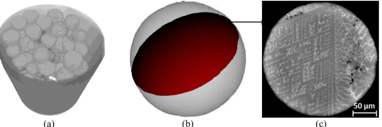
Synchrotron X-ray micro-tomography [9] is used to investigate the microstructure morphology of the droplets. Image acquisition and volume reconstruction were performed at ESRF on the ID19 beamline. This technique provides a three-dimensional representation of the droplets inside the glass capillary as shown in figure 1a. Two resolutions were used: a high resolution of 0.18 µm/pixel (field of view of 369 µm) to analyse in detail the fine microstructure of small droplets, and a medium resolution of 0.56 µm/pixel (field of view of 1146 µm) to scan either the bigger droplets, or several small droplets at the same time, which allows statistical studies. Two kinds of images are obtained depending on the post-processing technique used for the volume reconstruction: the standard filtered back-projection algorithm that provides images based on the difference in X-ray attenuation coefficient between the different phases in the droplet, and a reconstruction algorithm developed more recently from the work of Paganin et al. [10] based on phase retrieval. In both cases, the difference in grey level in the images is mainly due to the difference in density between the primary phase (aluminium, dark grey in figure 1c) and the eutectic (Al + Al2Cu, light grey in figure 1c). Thereafter,
the “Paganin” images will be used because they showed a better contrast between the two phases. Finally, the reconstructed volumes are analysed by using ImageJ software [11] to separate the droplets from each other. As the structure is highly complex due to three dimensional competition between dendrite arms, we focus on determining the position of planes showing characteristic morphologies, such as the dendritic plane as shown in figure 1b and figure 1c.
(a) (b) (c)
Figure 1. Typical X-ray micro-tomography result: (a) 3D-view of a capillary containing droplets, (b) position of a specific plane in a droplet and (c) corresponding image showing a dendritic structure. 4th International Conference on Advances in Solidification Processes (ICASP-4) IOP Publishing IOP Conf. Series: Materials Science and Engineering 117 (2016) 012055 doi:10.1088/1757-899X/117/1/012055
3. Results
3.1. Dendrite morphologies
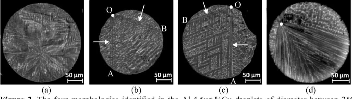
We have chosen to focus in the present article on the forty Al-4.5wt.%Cu alloy droplets cooled in argon, whose diameter is between 250 and 300 µm. By identifying characteristic planes in each droplet, four typical morphologies are distinguished. We do not intend here to extensively develop the characteristics of each of these morphologies but simply to present their main characteristics. The whole forty droplets are observed to be formed of a single grain. The first morphology shown in figure 2a is characterized by a highly branched microstructure. No clear nucleation position could be determined but it is worth noting that a rotation of 90° vertically (along OA) or horizontally (perpendicular to OA) from one characteristic plane lead to the observation of planes with similar morphology, suggesting that the dendritic microstructure developed along the usual <100> direction. For the second morphology figure 2b, the nucleation site (white dots noted O) as well as primary arms (white arrows noted OA and OB) can be distinguished and the morphology becomes highly branched (as in figure 2a) farther from the nucleation centre.
(a) (b) (c) (d)
Figure 2. The four morphologies identified in the Al-4.5wt.%Cu droplets of diameter between 250 and 300 µm: (a) highly branched morphology, (b) highly branched morphology with visible primary arms, (c) dendritic morphology and (d) “finger bundle” morphology. The nucleation position noted O is shown by a white dot and the primary arms noted OA and OB by white arrows.
The third morphology is shown in Figure 22c. The nucleation site can also be detected and the microstructure is dendritic with primary, secondary and tertiary arms clearly visible. It is worth noting that the secondary and tertiary arms developed in the same plane containing the two primary arms, more precisely on the left of the vertical primary arm OA and below the primary arm developing to the left OB. Finally, figure 2d shows an example of the fourth morphology. The nucleation site can still be found but characteristic planes are more difficult to determine because several arms with few branching expand from the nucleation centre and grow in an almost parallel manner. To our knowledge, such a microstructure has not been reported before and we termed this morphology “finger-bundle”. Then, the morphology becomes dendritic as in figure 2c farther in the droplet.
3.2. Evidence for <111> dendritic growth
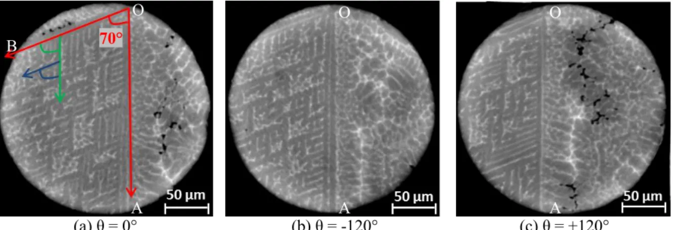
One striking feature of the dendritic microstructure in figure 2c is that the primary, secondary and tertiary arms are developing with an angle smaller than 90°, which is not expected for face-centered cubic structures in general [12]. Figure 3 shows characteristic dendritic planes found in another droplet. The two primary arms highlighted in red in figure 3a make an angle of approximately 70°. Similarly, the secondary arm highlighted in green makes a 70° angle with the primary arms and so on for higher arms orders. In addition, by rotating around the vertical primary arm noted OA in figure 3a, only two other similar dendritic planes are found: the plane in figure 3b by rotating of -120° and the plane figure 3c by rotating from +120°.
The angle values between the arms being characteristic of the growth orientation of the dendrites, they can help us identifying it. The angles measured on the dendritic microstructure in figure 3 are
O A B O A B
4th International Conference on Advances in Solidification Processes (ICASP-4) IOP Publishing IOP Conf. Series: Materials Science and Engineering 117 (2016) 012055 doi:10.1088/1757-899X/117/1/012055
actually coherent with a <111> growth orientation. Indeed, with this growth orientation, the theoretical angle between two primary arms is equal to 70.5° and the angle between planes containing primary arms is equal to 120°, in a perfect agreement with the previous measured angles. The measurements made for the presented dendritic planes can be easily extended to the eight primary arms and six dendritic planes identified in the droplet. Finally, by placing the nucleation centre of the dendrite at the centre of a cube, we could determine that all the primary arms are pointing towards the cube corners (figure 4), confirming that the eight primary arms are directed in the eight <111> directions.
(a) θ = 0° (b) θ = -120° (c) θ = +120°
Figure 3. Three of the characteristic planes identified in a dendritic droplet. From the plane shown in (a), we obtained the one shown in (b) by rotating from -120° along the OA, and the plane shown in (c) by rotating from +120°. The arrows highlight the primary, secondary and tertiary dendritic arms.
Figure 4. 3D-representation of the droplet with its surface in transparency and 6 dendritic planes in black. The droplet is placed in a cube with the nucleation centre at the centre and the primary arms correspond to the cube diagonals, illustrating the <111> growth orientation of the microstructure.
4. Discussion
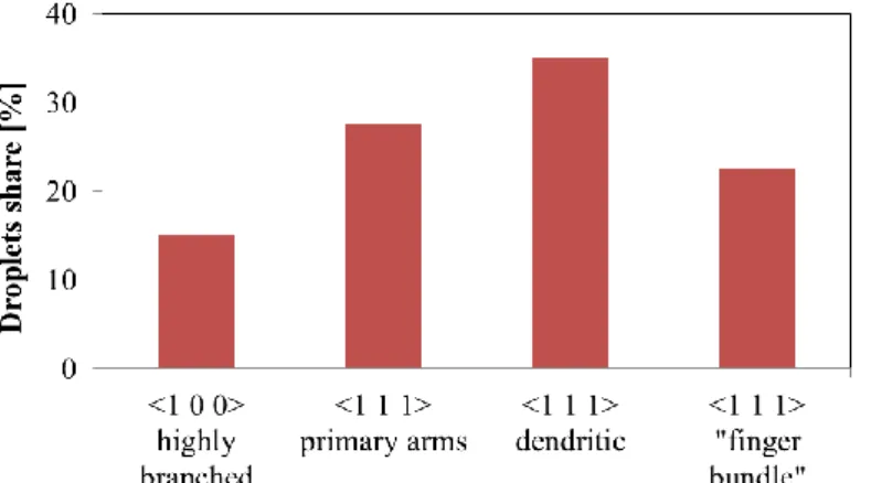
As previously mentioned, the <111> growth direction (actually found in 85% of the 40 studied droplets, as can be seen in figure 5) was not initially expected. Indeed, the aluminium-copper alloy is commonly considered to grow in <100> directions [13], as for the face-centered cubic (fcc) structures in general [12]. However, growth direction changes in fcc crystals have already been reported experimentally. Kahlweit et al. highlighted the growth orientation change of NH4Cl-H2O crystals from
<100> to <110> and then <111> with increasing growth velocity [14]. The authors investigated the growth orientation by varying the nucleation undercooling through solute composition and solidification temperature. Chan et al. suggested that, at low undercooling, the growth orientation is imposed by the anisotropy of interfacial free energy, while at high undercooling it is controlled by the “anisotropy of rate constant” [15]. By directionally solidifying this alloy, oscillations between these
70° O A B O A O A
4th International Conference on Advances in Solidification Processes (ICASP-4) IOP Publishing IOP Conf. Series: Materials Science and Engineering 117 (2016) 012055 doi:10.1088/1757-899X/117/1/012055
different growth modes were also seen by Gudgel et al. [16]. On the other hand, the investigation of Haxhimali et al. [17] on the dendrite growth orientation of directionally solidified Al-Zn alloys showed a change from <100> to <110> for a range of solute compositions. The latter result being independent of the solidification velocity, the authors concluded that the continuous orientation change is due to anisotropy variation of the surface energy and not to attachment kinetics anisotropy
for this dendrite orientation transition. Using EBSD analysis, Chen et al. showed that with Al-0.6wt.%Fe and Al-1.9wt.%Fe atomized using IA, a textured structure showing a preference in the
<111> direction was observed [18] . In the same way, Castle et al. recently reported a number of morphological transitions with increasing undercooling for a Cu-Ni alloy, interpreted as an extended transition between fully <100> and <111> growth orientations [19]. All these experiments suggest that the variation of interfacial energy anisotropy can induce a <100> to <110> transition, while the attachment kinetics anisotropy variation would explain the <111> orientation outbreak, with the transition to <111> linked to the solidification rate.
Figure 5. Droplet share of the four morphologies for the 40 droplets solidified in argon which diameter is between 250 and 300 µm.
This interpretation is coherent with our observations. Indeed, the solute composition and the process parameters being imposed, a distribution of the solidification velocity of the droplets can be the reason for the growth morphology distribution. As described in paragraph 3.1, the growth orientation seems to be <100> in highly-branched droplets (figure 2a) and we therefore can suppose that they formed at the slowest velocity. Then, for higher solidification velocity, the primary arms would start growing in <111> directions but the higher level arms that solidify later and more slowly would grow in <100> directions. This seems to correspond to the second morphology shown figure 2b. Then, when the velocity is even higher, the growth orientation remains < 111> in the whole droplet as illustrated figure 2c and figure 3. Finally, for the fastest velocities, the competition between several primary arms growing in the <111> direction leads to the kind of “finger bundle” morphology observed in figure 2d, then the dendritic structure is found back in regions of the droplet with slower solidification velocity.
Thus a range of solidification rates may be obtained in the IA production of droplets, even for imposed process conditions and for a given droplet size. The origin of the solidification velocity range can be the local thermal interactions between the droplets or a distribution of nucleation undercooling. This distribution would be large enough to induce a morphology distribution, from highly-branched to “finger-bundle”, passing by highly branched with visible primary arms and dendritic morphologies. 5. Conclusion
Synchrotron X-ray micro-tomography has been used to characterize Al-4.5wt.%Cu droplets formed by IA process. This characterization technique is non-destructive and enables to statistically analyse droplets in three-dimensions. The determination of characteristic planes by studying a large number of 4th International Conference on Advances in Solidification Processes (ICASP-4) IOP Publishing IOP Conf. Series: Materials Science and Engineering 117 (2016) 012055 doi:10.1088/1757-899X/117/1/012055
droplets of roughly the same size and formed under the same process conditions leads to the identification of four different morphologies. The morphologies were shortly described and a <111> growth orientation was highlighted. The existence of the four morphologies was attributed to a range of solidification velocity for droplets of the same batch. This work will be continued by analysing more precisely the three other morphologies. Moreover, droplet solidification modelling will be used to improve the understanding of the solidification velocity impact on kinetic anisotropy during dendritic growth.
Acknowledgements
This study has been performed in the framework of MIMOSA project funded by the French National Research Agency (ANR) in collaboration with the Natural Sciences and Engineering Research Council of Canada and Novelis. In addition, we would like to thank Barbara Fayard and Olivier Guiraud from Novitom for their technical support.
References
[1] Hatch J E 1984 (ASM International)
[2] Nussbaum G, Sainfort P, Regazzoni G and Gjestland H 1989 Scr. Metall. 23 1079–84 [3] Boettinger W J, Bendersky L and Early J G 1986 Metall. Trans. A 17 781–90
[4] Sudarshan T S and Srivatsan T S 1993 (CRC Press) [5] Prasad A 2006 PhD Thesis 70
[6] Henein H 2002 Mater. Sci. Eng. A 326 92–100
[7] Wiskel J B, Henein H and Maire E 2002 Can. Metall. Q. 41 97–110 [8] Federation M P I 2012 (S.l.: Metal Powder Industry)
[9] Nguyen-Thi H, Salvo L, Mathiesen R H, Arnberg L, Billia B, Suery M and Reinhart G 2012 Comptes Rendus Phys. 13 237–45
[10] Nugent K A, Gureyev T E, Cookson D F, Paganin D and Barnea Z 1996 Phys. Rev. Lett. 77 2961–4
[11] Abramoff M D, Magalhães P J and Ram S J 2004 Biophotonics Int. 11 36–42 [12] Dantzig J A and Rappaz M 2009 (EPFL Press)
[13] Kato H and Umeda T 1978 Metall. Trans. A 9 1795–800 [14] Kahlweit M 1970 J. Cryst. Growth 7 74–8
[15] Chan S-K, Reimer H-H and Kahlweit M 1976 J. Cryst. Growth 32 303–15 [16] Gudgel K A and Jackson K A 2001 J. Cryst. Growth 225 264–7
[17] Haxhimali T, Karma A, Gonzales F and Rappaz M 2006 Nat. Mater. 5 660–4
[18] Chen J, Dahlborg U, Bao C M, Calvo-Dahlborg M and Henein H 2011 Metall. Mater. Trans. B 1–11
[19] Castle E G, Mullis A M and Cochrane R F 2014 Acta Mater. 66 378–87
4th International Conference on Advances in Solidification Processes (ICASP-4) IOP Publishing IOP Conf. Series: Materials Science and Engineering 117 (2016) 012055 doi:10.1088/1757-899X/117/1/012055