TJ778 M4I G24
A COMIPUTATIONAL MODEL FOR ROTATING STALL AND INLET DISTORTIONS
IN MULTISTAGE COMPRESSORS by
Yifang Gong
A
COMPUTATIONAL MODEL FOR ROTATING STALL AND INLET DISTORTIONSIN MULTISTAGE COMPRESSORS by
Yifang Gong
GTL Report #230 March 1999
This research was supported by NASA Grants NAG3-953 (Dr. C. Drummond, Technical Monitor), NAG3-1567 (Drs. C. Drummond and K. Owen, Technical Monitors),
NAG3-2051 (Dr. K. Suder, Technical Monitor), and NAG3-2078 (Dr. J. Adamczyk,
MASSACHUSETTS INSTITUTE OF TECHNOLOGY
JUN
2ed'2002
JUN 2 7 2005 PARIF- S
A Computational Model for Rotating Stall and Inlet
Distortions in Multistage Compressors
by
Yifang Gong
Abstract
This thesis presents the conceptualization and development of a computational model for describing three-dimensional non-linear disturbances associated with instability and inlet distortion in multistage compressors. Specifically, the model is aimed at simulating the non-linear aspects of short wavelength stall inception, part span stall cells, and compressor response to three-dimensional inlet distortions. The computed results demonstrated the first-of-a-kind capability for simulating short wavelength stall inception in multistage compressors.
The adequacy of the model is demonstrated by its application to reproduce the following phenomena: (1) response of a compressor to a square-wave total pressure inlet distortion; (2) behavior of long wavelength small amplitude disturbances in compressors; (3) short wavelength stall inception in a multistage compressor and the occurrence of rotating stall inception on the negatively sloped portion of the compres-sor characteristic; (4) progressive stalling behavior in the first stage in a mismatched multistage compressor; (5) change of stall inception type (from modal to spike and vice versa) due to IGV stagger angle variation, and "unique rotor tip incidence" at these points where the compressor stalls through short wavelength disturbances. The model has been applied to determine the parametric dependence of instability inception behavior in terms of amplitude and spatial distribution of initial distur-bance, and intra-blade-row gaps. It is found that reducing the inter-blade row gaps suppresses the growth of short wavelength disturbances. It is also concluded from these parametric investigations that each local component group (rotor and its two adjacent stators) has its own instability point (i.e. conditions at which disturbances are sustained) for short wavelength disturbances, with the instability point for the compressor set by the most unstable component group.
For completeness, the methodology has been extended to describe finite ampli-tude disturbances in high-speed compressors. Results are presented for the response of a transonic compressor subjected to inlet distortions.
Acknowledgements
I would like to express my deep gratitude to those who made it possible for me to carry out this work at MIT. Without their support and contributions, this work would have been impossible to complete. In particular, I would like to acknowledge the following individuals and organizations.
First I would like to thank all members of my thesis committee, especially, Dr. Choon Tan, my thesis supervisor, for his continuous support and encouragement, and Professor Greitzer for his guidance as well as encouragement, and Professor Epstein for his support and insightful comments. Their expertise, guidance, and enthusiasm were invaluable to this research project.
People at the Gas Turbine Laboratory have been a particularly important part of my experiences at MIT. Their inputs, friendship, and good humor have fortified me through the many years spent on this work. I'm especially gratiful to Tonghua Shang, Ken Gordon, Joel Haynes, Duc Vo, and Patrick Shum, among many others.
The work has been supported by NASA Grant NAG3-953 (Dr. C. Drummond as technical monitor), NAG3-1567 (Drs. C. Drummond and K. Owen as technical monitors), NAG3-2051 (Dr. K. Suder as technical monitor) and NAG3-2078 (Dr.
J. Adamczyk as technical monitor). Additional Computational resources have been
provided by the LACE cluster at the NASA Lewis Research Center.
In addition, Scholars in turbomachinery community, Drs. Adamczyk, Cumpsty, Day, Hoying, Hynes, Longley, Marble, Strazisar all offered suggestions for improve-ments during various stages of the work.
I wish to express my gratitude to my family. Every one of them has supported
me through my entire life. From my parents, I have received tremendous love and guidance.
Finally, I wish to express my greatest gratitude to a particular person who has given the greatest support to this accomplishment. This particular person contributed her deepest love one could ever hope to receive. And this person is my wife, Hua.
Contents
1 Introduction 21
1.1 Introduction . . . . 21
1.2 Overview of Compressor Instabilities . . . . 22
1.2.1 Types of compressor instability in axial compressors . . . . 22
1.2.2 Onset of instability . . . . 24
1.2.3 Two Major Stall Inception Types . . . . 25
1.3 Experimental Observations on Short Wavelength Stall Inception . . . 27
1.3.1 Features of Short Wavelength Stall Inception . . . . 27
1.3.2 Experiments on Compressor Response to Rotating Inlet Distor-tions . . . . 28
1.3.3 Relation Between Local Stall Cells in Mismatched Compressor and Stall Inception through Short Wavelength Scale Disturbances 29 1.3.4 Existence of Short Length Disturbances Prior to Stall Point . 31 1.3.5 An Investigation of the Conditions Under Which Short Wave-length Stall Inception Occurs . . . . 35
1.3.6 A Summary of Short Wavelength Stall Inception . . . . 36
1.4 A Review of Current Modeling Capability . . . . 37
1.4.1 Stall Propagation Mechanism . . . . 38
1.4.2 Zero Slope of Characteristic as An Instability Criterion . . . . 38
1.4.3 Moore-Greitzer Theory . . . . 39
1.4.4 Three-dimensional and Non-linear Methods . . . . 40
1.6 Contributions . . . . 42
2 Development of A Computational Model 45 2.1 General consideration of the model . . . . 45
2.1.1 Desired Model Features . . . . 45
2.1.2 Simplifications of the Model . . . . 46
2.1.3 Preliminary Justification of The Infinite Number of Blade As-sum ption . . . . 46
2.2 Modeling of A Compression System . . . . 48
2.2.1 Flow in Ducts . . . . 50
2.2.2 Flow in Blade-rows . . . . 51
2.2.3 Plenum and Throttle . . . . 53
2.3 Construction of A Force Field Within Blade Rows . . . . 54
2.4 Implementation of the Model for Simulating the Short Wavelength Stall Inception . . . . 62
2.4.1 Disturbances . . . . 64
2.4.2 Determination of The Stall Point . . . . 64
2.4.3 Determination of The Stall Inception Type . . . . 65
2.5 Numerical method . . . . 68
2.6 Sum m ary . . . . 70
3 Model Assessment 71 3.1 Two-Dimensional Steady Flow Field with Inlet Distortion . . . . 72
3.2 Two-Dimensional Modal Wave . . . . 75
3.3 Three-Dimensional Modal Wave . . . . 76
3.4 Simulation of Stall Inception of A General Electric Four-Stage Com-pressor, Matched Build . . . . 78
3.5 The GE Four-Stage Compressor, Mismatched Build . . . . 87
3.6 Effects of IGV stagger on Stalling Behavior in the First Rotor . . . . 95
3.7 Sum m ary . . . . 98 8
4 Parametric Studies of the Short Length Scale Stall Inception 99
4.1 Type of Disturbance . . . . 100
4.2 Amplitude of disturbance . . . . 101
4.3 Axial location . . . . 104
4.4 Rotor Characteristic to the Left of the Peak Pressure Rise . . . . 105
4.5 Intra-Blade-Row Gap . . . . 107
4.6 Sum m ary . . . . 109
5 Additional Physical Aspects of Short Wavelength Stall Inception 111 5.1 Effects of Swirl Sensitivity . . . . 112
5.2 On the sources of the forcing impulses . . . . 116
5.3 Three-dimensionality in the short wavelength stall inception . . . . . 117
5.3.1 Rotating Stall Inception in a Compressor Represented by Multi-rectilinear-cascades . . . . 118
5.3.2 Rotating stall inception in a compressor represented by multiple two-dimensional cascades . . . . 120
5.4 Minimum Requirements in A Compressor Model for Short Wavelength Disturbances . . . . 122
5.5 Component Group and Its Implications . . . . 123
5.6 Routes to rotating stall . . . . 124
5.7 Effect of design flow coefficient . . . . 127
5.8 Sum m ary . . . . 133
6 Computational Flow Model for High-Speed Compressors 135 6.1 Governing Equations . . . . 136
6.2 Formulation of Body Force . . . . 138
6.2.1 A Form of Body Force for Representing a Blade Passage . . . 138
6.2.2 A Proposed Body Force Formulation . . . . 141
6.3 Numerical Examples: Compressor Response to Inlet Distortions . . . 144
6.3.1 Stage 35 Compressor Response to a Steady Total Pressure Dis-tortion . . . . 151
6.3.2 Stage 35 Compressor Response to Total Temperature Distortion 159 6.4 Stage 35 response to an abrupt total pressure distortion . . . . 164
6.5 Sum m ary . . . . 168
7 Summary and Conclusions, and Future work 169
7.1 Sum m ary . . . . 169 7.2 Conclusions . . . . 171 7.3 Recommendations for Future Work . . . . 172
A A Procedure of Formulating the Body Force 183
A.1 Determination of the body force from a three-dimensional flow in a
blade passage . . . . 184
A.2 Deducing
f,
andf,
as Functions of Local Flow Properties . . . . 186List of Figures
1.1 Compressor performance map and the effects of inlet distortions [57]. 22 1.2 Three types of compressor instability characterized in terms of the
respective pressure rise characteristics. . . . . 23 1.3 Three typical instability patterns in compression systems. . . . . 23
1.4 Velocity traces of eight sensors on the annulus show a typical stall inception through modal waves [45]. . . . . 26 1.5 Velocity traces of eight sensors on the annulus show the compressor
stall inception through short wavelength disturbances (spikes) [9]. . . 27 1.6 Emmons's rotating stall cell propagation mechanism. . . . . 28 1.7 Two types of compressor resonance response to rotating inlet distortions. 30 1.8 First stage pressure rise characteristic of the GE mismatched
compres-sor [60]. . . . . 31 1.9 Spike disturbances form and decay before stall (at time = 0). The
pressure traces, from sensors at different circumferential positions at the first rotor exit, are shifted relative to first trace so that disturbances traveling at 71% of rotor speed line up vertically. Guide lines identify propagating spikes. [56] . . . . 32 1.10 Spike disturbances form and decay near stall (at time = 0). The
pres-sure traces, from sensors at different circumferential positions at the first rotor exit, are shifted relative to first trace so that disturbances traveling at 71% of rotor speed line up vertically. Guide lines identify propagating spikes. [56] . . . . 33
1.11 Rotating stall is triggered as one spike grows and forms a large stall
cell.[56] . . . . 34 1.12 Effects of IGV stagger and the "unique rotor tip incidence" [5]. . . . . 35 1.13 A model for determining the stall inception type of a compressor [5]. . 36
1.14 A sketch of flow around a short wavelength disturbance. . . . . 37 1.15 Influence of slope of compressor pressure rise characteristic on stability
of disturbances. . . . . 39
2.1 The localized disturbance around a rotor blade row. The decay rate of the disturbance can be affected by the downstream stator. . . . . 47 2.2 The comparison of the complexity of the current model (b) with other
m odels. . . . . 49
2.3 Illustration of a compression system and the blade row modeling . . . 50
2.4 The characteristics of the rotor and stator of the first stage are con-structed. Only the right-to-the-peak portion of the stage characteristic is m easured. . . . . 55 2.5 Notations of total, static pressure, and velocity at the rotor inlet,
rotor-stator gap, and rotor-stator exit. . . . . 56 2.6 The C. distribution from leading edge to trailing edge. . . . . 60 2.7 Computed V1 profiles compared reasonably well with measured V1
pro-files at design and near stall flow coefficient. . . . . 61 2.8 Experimental evidence of tip-spikes prior to the development of stall at
time=0. The pressure traces, from sensors at different circumferential positions at the first rotor exit, are shifted relative to first trace so that disturbances traveling at 71% of rotor speed line up vertically. Guide lines identify propagating spikes. [56] . . . . 63 2.9 Axial body force impulse used to generate spike-shaped disturbances. 63
2.10 Computed < traces when a compressor stalls through short wavelength disturbances. . . . . 65
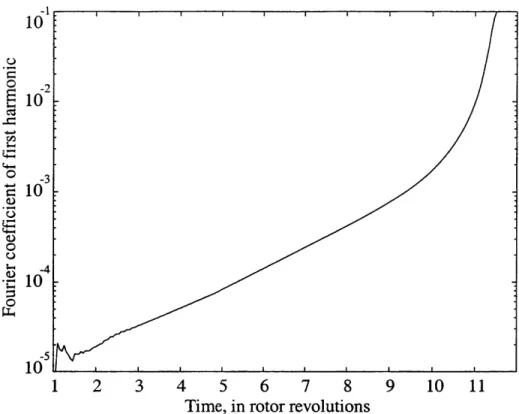
2.11 Evolution of Fourier coefficients of computed V shows a spike-shaped disturbance is sustained by the system, and causes the compressor to stall afterwards. . . . . 66
2.12 Computed V traces when a compressor stalls through long wavelength disturbances. . . . . 66 2.13 Evolution of Fourier coefficients of computed V, shows a spike-shaped
disturbance is suppressed after it is inserted into the system. The compressor stalls afterwards through long wavelength disturbances. . 67
2.14 The compressor which does not support short wavelength disturbances shows a clear modal wave evolution of first harmonic. . . . . 68 2.15 Illustration of fluxes evaluation around a cell in the blade row region . 69
3.1 The total-to-static pressure rise characteristic used in Section 3.1 and Section 3.2. . . . . 73 3.2 V distribution at compressor inlet face. The solid line is computed by
the computational model, and the dash line the analytical model. . 74
3.3 Flow redistribution is shown using Pt contours. The plot shows the low Pt region contracts when it reaches the compressor inlet face. . . 75
3.4 V, distributions near the compressor inlet show strong flow redistribution. 76 3.5 The
#
profile measured from the MIT three-stage compressor is wellpredicted by the computational model. The sensor location is at a location upstream of the SVG. . . . . 77 3.6 A schematic of MIT three-stage compressor with a Servo Guide Vane
(SGV) between the IGV and first rotor . . . . 77 3.7 A scaled schematic of the GE compressor represented by nine blade
rows and eight gaps. . . . . 81 3.8 Stage characteristic of GE compressor. . . . . 82 3.9 Measured tip
#
traces at the inlet of first rotor for a compressor stallingvia short wavelength route. . . . . 83 3.10 Calculated tip
#
traces at inlet of first rotor . . . . 833.11 Evolution of first harmonic of V, at tip of the first rotor inlet for small
amplitude long wave length disturbance. . . . . 84
3.12 Two different stall points are calculated for spike-shaped and linear
disturbances in the GE matched compressor. . . . . 84
3.13 Tip Vx within eight gaps at six time instances during the development
of the initial disturbance. . . . . 85
3.14 The computed tip
#
traces from the rotor exit show the evolution of a spike-shaped disturbance. The compressor is a single-stage configura-tion of the GE compressor. . . . . 86 3.15 Measured and computed stage one characteristics for the GEmis-matched compressor. Circles denote the progressive stall, which de-viates from the axisymmetric characteristic (solid line). . . . . 88 3.16 Measured velocity trace showing a localized stall cell [60]. . . . . 91 3.17 Computed velocity trace showing a localized stall cell. . . . . 91 3.18 Computed flow coefficient contours of a localized stall cell in the first
stage of the GE mismatched configuration. A tangential extent equal to 6 blade pitches is shown. . . . . 92 3.19 A simple analysis gives a good trend of the number of local stall cells
in the mismatched GE four-stage compressor. . . . . 94
3.20 First stage characteristics with the stall point and inception type
indi-cated for different IGV staggers. Measured by Camp and Day [11]. . 97 3.21 First stage characteristics with the stall point and inception type
com-puted for different IGV staggers . . . . 97
4.1 Changes in stall point and inception type for different type of inposed disturbances. . . . 101
4.2 Effects of initial spike forcing amplitude on stall point and inception type. ... ... ... ... 102
4.3 Effects of disturbance amplitude. A large amplitude disturbance could cause blade row stall when the overall flow coefficient is in negative sloped region. . . . . 103
4.4 Changes in stall point and inception type with location of initial spike. 104 4.5 Several different left side rotor characteristics was used for the study. 106
4.6 Computed results of stall characteristics for mismatched compressor with different left-side characteristics. . . . . 106
4.7 Effects of IGV-R1, Ri-S1, and S1-R2 gap lengths on stall point and inception type. . . . . 108 5.1 Flow coefficient and flow angle distribution at the inlet of the first rotor. 113
5.2 Flow coefficient and flow angle distributions at tip of the first rotor inlet. 114
5.3 (a) Effects of inlet swirl on the pressure rise; (b) Effects of inlet swirl on the relative flow angle. . . . . 115
5.4 An illustration of the multi-rectilinear-cascade representation of a mul-tistage com pressor. . . . . 119 5.5 The stall point and its inception type of the multi-cascade compressor
along with the stall points and their types with hub-forcing and tip-forcing in the GE compressor. . . . . 119 5.6 Stall point calculated using a two-dimensional row by row
represen-tation with finite spike-shaped forcing, and the stall points computed using the three-dimensional model. . . . . 121
5.7 There are four component groups in the GE four-stage compressor. . 123 5.8 Velocity traces show 1.5 times rotor frequency disturbance at the front
stage prior to the final stall cell [11]. . . . . 125 5.9 Velocity traces show 13 times rotor frequency disturbance at the front
stage prior to the final stall cell [11]. . . . . 125 5.10 Casing static pressure traces at the first stage rotor inlet during the
transition from twelve local stall cells to a single stall cell. GE com-pressor, mismatched build [56]. . . . .. 126
5.11 Effects of design flow coefficient on the compressor stall characteristic 128 5.12 Velocity trangle and notation for a compressor stage. . . . . 132 5.13 Slope of rotor characteristic at the peak of the stage characteristic for
different stage peak flow coefficients. . . . . 132
5.14 The stalling flow coefficient and stall inception type of ten compressors. The compressor and flow coefficient are listed in Table 5.1. The data show that compressors with low stall flow coefficient stall through short wavelength type. . . . . 133
6.1 The flow in a blade passage is modeled locally as a flow in a straight channel. . . . . 139 6.2 The body force due to pressure gradient in a staggered channel. The
velocity is along the blade passage; and the pressure gradient is also in the blade passage direction. The pressure gradient has a component in the circumferential direction, so it creates the pressure difference (P3-Pi) across the blade. . . . . 140
6.3 The flow in a blade passage in (x, 0) plane. . . . . 143 6.4 The computational domain (solid line) is based on the real geometry
except for the exit region denoted by dash line. Flow variables taken at the four indicated locations are used for comparison between mea-surements and computed results. . . . . 145
6.5 The computational mesh around the rotor and stator. The leading edges and trailing edges are indicated by thick lines. . . . . 146
6.6 The computed compressor performance map of Stage 35. . . . . 147
6.7 The measured compressor performance map of Stage 35 [58]; the filled
circle donates the design point. . . . . 147
6.8 Computed Mach number distribution in the rotor. The compressor is
operated at 100% design rotational speed and mass flow rate of 20.2 kg/sec. The model captures a shock at the leading edge. . . . . 148
6.9 The computed static pressure, entropy, and relative flow angle
distri-bution from the leading edge to the trailing edge at the tip region of Rotor 35. The leading edge position is at the first circle symbol, and trailing edge the last one. The results show that a shock is captured at the leading edge in three grid points. . . . . 149
6.10 The computed and measured [58] loss coefficient profiles of Rotor 35
at 100% rotational speed and 20.2 kg/sec mass flow rate. . . . . 150 6.11 The computed and measured [58] deviations of Rotor 35 at 100%
ro-tational speed and 20.2 kg/sec mass flow rate. . . . . 150 6.12 The computed and measured [65] total and static pressure at the
up-stream and downup-stream locations of Stage 35. . . . . 154
6.13 The computed and measured [65] flow coefficient at the upstream
lo-cation of Stage 35 . . . . . .. . . . . 154 6.14 The computed axial velocity distributions at the upstream location,
rotor inlet, rotor exit, and stator exit. The 1200 low Pt sector is imposed far upstream . . . . 155 6.15 Computed flow coefficient distributions at the upstream location and
the rotor inlet . . . . 155 6.16 Computed axial velocity distribution at the rotor inlet of Stage 35
versus velocity distribution at the rotor inlet of the compressor in Hynes and Greitzer [35]. . . . . 156 6.17 The loading on the front rotor is changed due to the induced swirl at
the compressor inlet. . . . . 156 6.18 The computed total pressure distributions at the exit of the compressor
with total pressure distortion upstream . . . . 157 6.19 The computed total temperature distributions at the exit of the
com-pressor with total pressure distortion upstream. . . . . 157 6.20 The local operating point around the annulus of Stage 35 subjected to
6.21 The flow angle distribution at the mid-span of the rotor inlet for
Stage35 with a total pressure distortion upstream. . . . . 158 6.22 The distributions of the aerodynamic force on blades along the annulus.159 6.23 The computed axial velocity distributions far upstream, at the rotor
inlet, rotor exit, and stator exit. A square wave total temperature is imposed far upstream of the compressor. . . . . 161
6.24 The computed flow coefficient distributions upstream and at rotor inlet for Stage 35 with inlet Tt distortion. . . . . 161 6.25 The computed total pressure and total pressure distributions at the
exit of the compressor with a total temperature distortion upstream. 162 6.26 The computed total pressure distributions at the exit of the compressor
with a total temperature distortion upstream. . . . . 162 6.27 The local operating point around the annulus of Stage 35 subjected to
a far upstream square wave total temperature distortion. . . . . 163 6.28 The flow angle distribution at the mid-span of the rotor inlet for Stage
35 with a total temperature distortion upstream . . . . 163 6.29 The distributions of the aerodynamic force on blades around the annulus. 164 6.30 The computed mean mass flow traces at the upstream location,
com-pressor inlet, comcom-pressor exit, and downstream location. An abrupt inlet Pt distortion is imposed into the system at time = 0 revs . . . . 166 6.31 The computed mean static pressure traces at the upstream location,
compressor inlet, compressor exit, and downstream location. An abrupt inlet Pt distortion is imposed into the system at time = 0 revs. . . . . 166 6.32 The computed flow coefficient profiles at the mid-span of the
compres-sor inlet at four time instants. An abrupt inlet Pt distortion is imposed at the far upstream location at time = 0 revs. . . . . 167 A.1 The f, and
f,
are defined on each cell of the pre-generated mesh. . . 187List of Tables
3.1 A comparison between computed and theoretic growth rates and phase
speeds of the first circumferential mode. . . . . 75 3.2 A comparison of growth rate and phase speed computed using the
computational model and analytical model . . . . 78 3.3 The design parameters of General Electric four-stage compressor. . . 79
3.4 The computational mesh distribution used in the simulation of the GE four-stage compressor. . . . . 80 3.5 Comparison between computation and measurement . . . . 81 3.6 Summary of the comparison between computation and measurement . 92 5.1 A list of compressors, their stall flow coefficients, and stall inception
types. ... ... 131 6.1 Some design parameters of Stage 35. . . . . 145
Chapter 1
Introduction
1.1
Introduction
Compressor instability is a major limiting factor on gas turbine engine operating range, performance, and reliability. The instability, either in a form known as rotating stall or surge, occurs at an operating point with low mass flow and high pressure rise. To avoid such instabilities, the compressor (and hence the engine) has to operate at an operating point corresponding to lower pressure ratio so that an adequate stall margin is maintained (Fig. 1.1). The stall margin can be considerably reduced in operating environments for which the inlet conditions are non-uniform.
Recent experimental data [9, 60] have elucidated the importance of three-dimensional and non-linear aspects of compressor flow instability behavior which are beyond the scope of current flow models. The work described in this thesis constitutes a research which addresses these aspects. The effort is focused first on developing a compu-tational model to delineate compressor instabilities in multistage compressor under uniform as well as non-uniform flow situations, followed by its preliminary applica-tions to establish causal links between instability behavior and compressor design characteristics.
In this chapter, phenomena associated with compressor instability, including short wavelength stall inception in multistage compressors [9], are reviewed. This is then followed by a review of the current modeling capability. The objectives and
7.0
-Operating line
Surge line Stall 6.0 Surge line with
inlet distortion 5.0 97% 100% 4.0 -'94% 186% of design 380% rotational speed 3.0 I __ _ _ _ 25 30 35 40 45 50
Corrected mass flow
Figure 1.1: Compressor performance map and the effects of inlet distortions [57].
scope of the thesis are described, followed by a concise delineation of the contributions.
1.2
Overview of Compressor Instabilities
1.2.1
Types of compressor instability in axial compressors
Three types of instability behavior have been observed at compressor operating points beyond the surge line (Fig. 1.2), which are progressive stall, 'abrupt' stall, and surge. With progressive stall, there is a gradual deterioration of pressure rise. This happens for example when a multistage compressor is operated at a speed below the design speed. The flow field associated with this type of instability is illustrated in Fig. 1.3(a) which shows several part-span stall cells rotating around the annulus. This flow pattern usually occurs in one or several stages in a multistage compressor.
'Abrupt' stall shows a sudden drop of pressure rise at the compressor surge line, with the formation of a full span stall cell (Fig. 1.3(b)). The stall cell has an axial
~, hysteresis I / I / I /
I
T I 4' / 44a) progressive stall b) 'abrupt' stall c) surge
Figure 1.2: Three types of compressor instability characterized in terms of the respective pressure rise characteristics.
low flow rate regions
... ... ...
a) part span stall cells b) full span stall cell c) surge Figure 1.3: Three typical instability patterns in compression systems.
extent that encompasses the whole compressor; this explains the large drop of pressure rise (in contrast to the situation in the part-span stall cell pattern). To recover from this type of stall pattern, the throttle has to be moved to a position corresponding to a flow coefficient (or corrected mass flow) much larger than that at which the compressor would stall upon throttle closing. This effect is usually referred to as hysteresis, shown in Fig. 1.2(b).
Surge is a one-dimensional flow oscillation through the whole engine (Fig. 1.3(c)). During an engine surge, a flame can often be seen at the intake and exhaust as the combustion moves forward and backward from the combustor.
1.2.2
Onset of instability
Predicting the condition at which instability will occur in a compressor requires an understanding of the flow processes leading to the onset of the instability. The phe-nomena described in the previous subsection are the final forms of instability. And it is important to distinguish the final form from the onset of instability. The transition from initial disturbance to final stall or surge can usefully be divided into three stages
(1) inception; (2) development; and (3) final flow pattern. The inception stage is the
period when disturbances start to grow (flow becomes unstable). It defines the oper-ating point and conditions for which instability occurs. In practice, the disturbances will take a finite amount of time (ranging from a few to several hundred rotor revo-lutions) to grow into final stall or surge, so that the inception stage can be viewed as the early development of the unstable flow.
For some compressors, the inception stage consists of the linear growth (extending up to several hundred rotor revolutions) of disturbances of infinitesimal amplitude, while in others the inception stage only extends over one to two rotor revolutions after its detection. The inception stage is the major focus of the instability modeling and prediction.
The development stage, which includes all the processes after the inception stage before the final flow pattern to be reached, is usually of less importance. It is often the case that one final form of instability in one compressor could be the pre-stage of
the final form in another compressor. For example, rotating stall might cause surge in some compressors, as noted by Greitzer [26]:
The global (system) instability is a basically one-dimensional phenomenon, involving on overall, annulus averaged, compressor performance curve. For typical volumes, lengths, and throttle characteristics this must generally be slightly positive sloped for system instability to occur. We have also seen that the axisymmetric flow through a compressor can be unstable to two- (or three-) dimensional infinitesimal disturbances, and that this local instability marks the inception of rotating stall. However, the onset of this rotating stall is very often associated with a precipitous drop in the overall ("one-dimensional") pressure-rise mass-flow curve of compres-sor performance. In other words, the inception of rotating stall can lead to a situation where the instantaneous compressor operating point is on a steeply positively sloped part of the characteristic, with a consequent violation of the dynamic and/or the static instability criteria.
In this sense, part span stall could be the pre-stage of full span rotating stall. This aspect will further be elaborated in Section 5.6.
1.2.3
Two Major Stall Inception Types
Two major inception types have been experimentally identified: modal waves, and spikes. Modal waves are exponentially growing long wavelength (length scale compa-rable to the annulus) small amplitude disturbances. The rotating speed of this type of disturbance is in the range between 20% to 50% of rotor speed. Figure 1.4 shows velocity traces during the transition process from small amplitude pre-stall waves (modal waves) to the fully developed stall pattern. Modal waves penetrate the whole compressor in the axial direction, so they can be detected by sensors at any locations at the inlet, exit, or within the compressor. Usually, this type of stall inception oc-curs at a point near the peak of the characteristic. This type of inception can be well described by linear stability theory. The theory developed by Moore and Greitzer [51]
53% 53% 50% 46% 46% 46% 1-.0 Probe #8 0.5 o0. Probe #7 -
0.5
'i2ii
I
0.0T Probe #5 ~0.5 1pn 0.0 Probe #4 [4 40 0.5 S0.0 Poe#l.,'tLLA
prdce th 0r-s5l modal wave'- befor maurmet wretke [9 2]
o0.0 Probe #2
~05
0.0 I
J015
C1 00 Probe #1-. -I
0 2 4 6 8 10 12 14 16
Time (rotor revolutions)
Figure 1.4: Velocity traces of eight sensors on the annulus show a typical stall inception through modal waves [45].
predicted the pre-stall modal wave before measurements were taken [49, 23].
The other inception mechanism is the growth of localized non-linear short wave-length (with wave-length scale of several blade pitches) disturbances [9], often referred to as "spikes". This type of stall inception is referred to as "short wavelength stall in-ception". Figure 1.5 shows velocity traces during a compressor stalling through short wavelength disturbances. The inception starts as one or several spike-shaped finite amplitude disturbances within the tip region of a particular stage. Usually, the dis-turbance develops into a large full span stall cell within three to five rotor revolutions. The initial rotating speed of this type of disturbances is around 70% of rotor speed, substantially higher than that for the typical modal wave speed. No existing model has been demonstrated to be capable of describing this type of phenomenon. The lack of this capability motivates this research project.
00
C,,
0
:Stall cell speed: 7 No modal perturbations-'
5
3
2 Emerging stall cell
0. 5. 10. 15. 20. 25.
Time (rotor revolutions)
Figure 1.5: Velocity traces of eight sensors on the annulus show the compressor stall inception through short wavelength disturbances (spikes) [9].
1.3
Experimental Observations on Short Wavelength
Stall Inception
The experimental observations associated with short wavelength stall inception are summarized in this section.
1.3.1
Features of Short Wavelength Stall Inception
Short wavelength stall inception first was identified by Day [9], but it has since been observed in many compressors [11, 17]. So far, the phenomena have only been roughly defined in a descriptive manner. From experimental observations [9, 11, 17, 60], a short wavelength type of stall inception is initiated by one or several disturbances which are localized in the tip region of a specific stage in a multistage compressor. Its circumferential width is about 2-3 blade pitches, with a high rotating speed (70% rotor speed), as well as a high growth rate (it takes 3-5 rotor revolutions from emerging of initial disturbance to forming a large stall cell) relative to the modal wave type of
--7 -9 o 41 7-4 44447
compressor
blade row
direction of
stall propagation
stall cell
Figure 1.6: Emmons's rotating stall cell propagation mechanism.
stall inception.
Day conjectured that the inception is initiated by blade passage events (analogous to the argument offered by Emmons [15] and shown in Fig.1.6).
1.3.2
Experiments on Compressor Response to Rotating
In-let Distortions
Longley et al [44] investigated the effects of rotating inlet distortions on compressor stability in several compressors, and found that there are two types of compressor response (measured in terms of the stall margin vs. rotating speed of the distortion): one shows a single resonance peak corresponding to a large decrement in stall margin when inlet distortion is rotating at around 0.4 rotor speed in the direction of rotor
28
rotation (Fig. 1.7(a)); the other shows two resonance peaks at 0.3 rotor speed as well as at 0.75 rotor speed (Fig. 1.7(b)). The compressors which show one resonance peak stall through modal waves while the other exhibit the spike type of stall inception. Thus the respective characteristic response of the compressor corresponds to two types of observed stall inception mechanisms which have different impact on stall margin due to rotating inlet disturbances.
1.3.3
Relation Between Local Stall Cells in Mismatched
Com-pressor and Stall Inception through Short Wavelength
Scale Disturbances
An interesting experiment has been conducted on a mismatched four-stage low speed compressor with the rotors in the latter three stages deliberately re-staggered away from stall [60]. The type of stall inception of the compressor in a matched build (i.e. four identical stage configuration) was spike type.
Measurements show that upon reducing the flow coefficient, the first stage still stalls at about the same flow coefficient as in the matched build (Fig. 1.8). The pressure rise then reduces gradually as the flow coefficient is decreased, similar to the progressive stall characteristic shown in Fig. 1.2(a). The stall cells are localized to the first stage. It is hypothesized that the influence of downstream stable stages limits the extent of stall cell.
The extent of these stall cells has the same order as that of spikes associated with the short wavelength stall inception. The rotational speed is the same as that of spikes. The similarity between the local stall cells, which are in its equilibrium state, and the spikes, which are in transition, indicates a link between the two phenomena. Therefore, the resulting knowledge from examining these local stall cells can be of utility in assessing the observations on short wavelength stall inception.
Uniform inlet low range Stationary distortion flow range
f
I
00CD0 00 00 Minimum flow range with rotating distortion 00 -- f o00 c*i 0 o Experimental data, 500 rpm o Experimental data, 350 rpm Counter Rotation + - Co-rotation-0.5 0.0 0.5
Screen rotating speed, in rotor speed (a) Single resonance peak
0 Design point flow coeffici * Uniform flow stall point o Experimental data - Calculation Uniform inlet * flow range
1=
T
Stationary distortion flow rangef
entMinimum flow range with rotating distortion
C
-Counter rotation -a w Co-rotation
-0.5 0.0 0.5
Screen rotating speed, in rotor speed
1.0
(b) Two resonance peaks
Figure 1.7: Two types of compressor resonance response to rotating inlet distortions.
0.6 CI) CA) :05 0.5 0.4 -1.0 1.0 0.56 0.52 0.48 0.44 C,, -0 0 0.40 0.36 -1.0 .f
Stall point for Mismatched compressor -- matched compressor Tg 0.24 stage 2-4 0 9 0 03 0 C20 0 0 stage 1 0.20 0.161. 0.30 0.34 038 0.42 Vx/ Utip
Figure 1.8: First stage pressure rise characteristic of the GE mismatched compres-sor [60].
1.3.4
Existence of Short Length Disturbances Prior to Stall
Point
Using a correlation method to analyze the measurements during the stall inception
of the GE compressor, Park [56] found that spike-shaped disturbances existed prior
to stall. He observed the short wavelength disturbances hundreds of rotor revolutions before the actual stalling event occurs (Fig. 1.9). These disturbances were seen to form and decay until stalling of the compressor takes place (Fig. 1.10 and Fig. 1.11). The frequency of the forming-decaying activity increased as the instability was approached through throttle closing.
One implication of his work is that the short wavelength stall inception can be
initiated by existing localized non-linear disturbances. This finding is not in accord
with linear theory, which is based on the growth of infinitesimal disturbances.
Park also sought the best sensor location for the detection of short wavelength
-375 -373 -371 -369
Time, in rotor revolutions
Sensor Locat'n (deg.) 315 225 210 200 180 135 90 45 0 -365 -367
Figure 1.9: Spike disturbances form and decay before stall (at time = 0).
pressure traces, from sensors at different circumferential positions at the first exit, are shifted relative to first trace so that disturbances traveling at 71% of speed line up vertically. Guide lines identify propagating spikes. [56]
The rotor rotor 21 1 I-, 4-6 0 Jill', 11111 L I A , 11, 1111''1 J 6 , I 1 1111111 l; ''II I 11111111 11 I'll 111111 0 14 ,10 270 1.1 0.5
1.5
0.5
0
-20 -19 -18 -17 -16 -15 -14
-Time, in rotor revolutions
Sensor Locat'n (deg.) 315 270 225 210 200 180 135 90 45 I' l i l .IN 1 11 P ll -12 -11 -10 13
Figure 1.10: Spike disturbances form and decay near stall (at time = 0). The
pressure traces, from sensors at different circumferential positions at the first rotor exit, are shifted relative to first trace so that disturbances traveling at 71% of rotor speed line up vertically. Guide lines identify propagating spikes. [56]
0
2
/-6 1
-5 -4 -3 -2 -1 0 1
Time, in rotor revolutions Figure 1.11: Rotating stall is triggered as one spike cell.[56]
2 3 4
grows and forms a la
Sensor Locat'n (deg.) 315 270 225 210 200 180 135 90 45 0 5 rge stall
j
fiJI1411 q-V %0^ INIIIIIIII 11111111PIAL- I-A
rTFj 11111 ofr A. .5 1 0.5 0
1.0 Contours of rotor 1 0.9 tip incidence 00 - -2- -- .-- 20-0.6 -2 ~ -150 -100 -40~ -5@ 0.4 00 +S- IGV 0.2 Stall inception +1C 0 stagger 9 spikes +15- change o modes +20. 0.0 1 1 1 1 1 1 1 1 i 0.45 0.50 0.55 0.60
Figure 1.12: Effects of IGV stagger and the "unique rotor tip incidence" [5].
earliest and strongest signals. This observation suggests that the initial spike-shaped disturbance assume the largest amplitude at the rotor exit.
1.3.5
An Investigation of the Conditions Under Which Short
Wavelength Stall Inception Occurs
From experimental observations, Camp and Day [4, 5] concluded that the spike-type stall inception occurs at a "unique rotor tip incidence" (Fig. 1.12). They examined a specific compressor with different JGV stagger angles and found that the stall points line up on a constant rotor tip incidence line whenever the compressor shows spike as its stall inception mechanism. The stall inception mechanism could be switched between modal type and spike-type for the same rotor and stator but with different IGV stagger. The overall trend is that when the first rotor is highly loaded (higher pressure rise for the given flow coefficient), the compressor tends to show spike-type inception, otherwise it shows the modal type of stall inception. These experiments suggest that the first-stage rotor is the key component responsible for the spike-type stall inception.
Critical rotor Critical rotor
incidence incidence
WPeak Peak
Flow coefficient Flow coefficient a) Modal stall inception b) Spike stall inception
Figure 1.13: A model for determining the stall inception type of a compressor [5].
Based on their observation, Camp and Day proposed a "unique rotor tip in-cidence" as a short wavelength stall criterion (Fig. 1.13). When this incidence is reached before the peak of the compressor characteristic, the compressor will stall through short wavelength disturbances; otherwise the compressor will stall at the peak pressure rise and show modal waves as its stall inception type.
1.3.6 A Summary of Short Wavelength Stall Inception
From experimental observations, one can conclude that short wavelength stall incep-tion is an important type of stall incepincep-tion. Based on the observaincep-tions, an approx-imate flow pattern around a short wavelength disturbance can be deduced. Figure
1.14 illustrates the shape of a short wavelength disturbance on the (x, r) plane, and
(x, 0) plane in the tip region and the resulting flow field associated with the presence
of the low flow region. The sketch illustrates several features that are essential for any proposed flow model development:
1. Flow redistribution within the gap of the stage where the short wavelength
disturbance is initially located (the implication is that a lumped compressor model cannot resolve this type of disturbances).
lo flow rat rotor stator - x
-I
o
W x U low rotor flow rat( rotor statorFigure 1.14: A sketch of flow around a short wavelength disturbance.
2. Flow redistribution within a blade row. So the flow at the leading edge of a blade passage can be significantly different from that in the rear part of the blade passage. This implies that a description based on the actuator disk concept cannot represent the flow field around such a short wavelength disturbance.
1.4
A Review of Current Modeling Capability
There are two central issues of rotating stall prediction: rotating speed and instability point, but from the practical point of view, only the instability point is of real
con-cern. Of engineering value is the ability to establish a causal link between instability behavior and compressor design characteristic.
1.4.1
Stall Propagation Mechanism
The first rotating stall model was the analysis and physical description proposed by Emmons [15] (see also Iura and Rannie [36].) Figure 1.6 shows the mechanism of stall propagation. Due to the flow redistribution upstream of a stall cell, a high incidence angle appears in the flow region ahead of the stall cell moving direction, while in the flow region behind the stall cell, the incidence angle is reduced. Therefore, at one side, flow redistribution causes the blades to stall, while at the other, blade loading is reduced, so the blade will get out of stall. Although the sketch only shows one of several possible stall propagation mechanisms, the idea is so intuitive that it is widely accepted by both academic and industrial communities.
Cumpsty and Greitzer [7] used the balance between acceleration in the rotor, stator, and upstream and downstream ducts to argue that the rotating speed of stall cell is determined as the speed at which the unsteady inertial effects in rotors are balanced by the unsteady inertial effects in stationary components. Their model predicted well the measured speed of rotating stall cells. The results suggest that although the flow redistribution idea is intuitive, the key mechanism for propagation is due to the inertial effects in blade rows and ducts. Later, Longley [43] showed that the flow redistribution effects do contribute to the rotating speed of stall cells.
1.4.2
Zero Slope of Characteristic as An Instability Criterion
The most well-known instability criterion, which states that the instability will occur at the zero-slope point (peak) of the characteristic, was proposed by Dunham [14]. He found that at the zero slope of total-to-static pressure rise characteristic, the compressor flow field is neutrally stable (i.e. disturbances do not decay).
A static stability argument for the criterion can be illustrated in Fig. 1.15. If a
compressor is operated in the negatively sloped region, for a small amplitude
lower pressure rise higher pressure rise
C.)Z
>6 >
higher pressure rise lower pressure rise a) A disturbance is suppressed by the compressor b) A disturbance is amplified by the compressor
in negatively sloped characteristic region in positively sloped characteristic region Figure 1.15: Influence of slope of compressor pressure rise characteristic on stability
of disturbances.
bance superimposed on an axisymmetric flow field, the higher flow coefficient region gets lower pressure rise (axial force), while the lower flow coefficient region gets higher pressure rise. Therefore the flow in the higher flow rate region is decelerated and the flow in the lower flow rate region accelerated, thus the disturbance is suppressed. However, if a compressor is operated in the positively sloped region, a disturbance will be amplified, leading to instability. One point to be noted in Dunham's model is that it does not involve the rotating aspect of disturbances. This might indicate that the key mechanism of instability is separated from the mechanism of rotation. It has been shown by some later models [6, 55] that the rotating aspect of a stall cell alters the instability point only slightly.
1.4.3
Moore-Greitzer Theory
Moore [50] modeled a compressor using a lumped compressor representation with a postulated axisymmetric pressure rise characteristic. His model was able to pro-duce the right trends of rotating speed of stall cells for different number of stages, and also the zero-slope criterion of total-to-static pressure rise characteristic as the neutral stability point. The model was subsequently extended to predict compressor performance and instability with inlet distortions [35].
Although most of the work and development of Moore-Greitzer's model has been for linear cases, the model itself is not limited to small amplitude disturbances. For
ex-ample, an inlet distortion can be viewed as a stationary large amplitude disturbance. Mathematically, general non-linear disturbances are very difficult to be treated an-alytically; however modern CFD methods can be used to simulate the evolution of any type of disturbances in the system. Longley [45] and Hendricks et al [32] used this idea to simulate instability behavior in high-speed compressors. Escuret and
Garnier [17] extended the method to three-dimensional cases.
1.4.4
Three-dimensional and Non-linear Methods
Some rotating stall phenomena, like part-span stall and short wavelength stall in-ception, are three-dimensional and non-linear in nature. Some early efforts [67] to capture the former did not show much positive results mostly due to the lack of computational resources. Recently, several CFD methods have been used to simulate compressor instability [31, 34]. One advantage of these methods is that they can relate the blade passage events to the instability. Hoying et al [34], based on the computational results, found that the tip vortex movement could cause local flow field breakdown which subsequently causes a stall cell in a single blade row. One uncertainty of these calculations is that they are performed on a single rotor blade row, since no data are available on short wavelength stall inception in a single rotor. Although CFD can play a potential role for implementing computation to provide information on instability behavior that is difficult to measure in a laboratory/test rig, such simulations are still beyond the presently available computational resources for multistage axial compressors.
There is another class of methods that uses both modeling and CFD technique to model the flow in a compression system. These methods could handle three-dimensional nonlinear flow phenomena in a practical manner and require reason-able amount of computational resources. These methods have been demonstrated to be able to compute steady three-dimensional inlet distortion cases [3], long wave-length disturbances in a three-dimensional compressor [17] and disturbances in two-dimensional high-speed compressors [32]. Conceptually this type of model is able to handle non-linear three-dimensional disturbances (e.g. spikes) in a compressor,
however no effort/calculations have been made to demonstrate this.
In summary, current modeling capability has been successful for the modal type disturbances, but no model describes the spike type of stall inception. The desire to understand the short wavelength disturbances in a compression system and the lack of the capability to model these types of three-dimensional non-linear disturbances in a compressor motivate the current research project.
1.5
Scope of the thesis
The goals of the research project are:
* to develop a methodology for describing unsteady three-dimensional
distur-bances associated with flow instability phenomena in a compression system;
* to assess the methodology for predicting both linear long wavelength and
non-linear short wavelength disturbances;
* to assess the effects of design parameters on the type of stall inception and the
instability point.
* to demonstrate the usability of the methodology for high-speed compressors in
situations with general type of inlet distortions.
Some specific questions of engineering interest are:
1. What is the simplest model capable of describing the short wavelength
distur-bances?
2. What are the key design characteristics which affect the instability point and its inception type?
3. When does a compressor exhibit short wavelength stall inception?
The thesis is organized as follows: Chapter 2 presents the development of the computational model; Chapter 3 presents an assessment of the model against known results; Chapter 4 describes a limited parametric study to reveal the impact of some relevant design parameters; Chapter 5 discusses the implication of the results; Chapter
6 extends the model to high-speed compressors with inlet distortions; Chapter 7
presents a summary and conclusions. The Appendix describes a way of developing a body force representation for blade-rows based on experimental measurements for high-speed compressors.
1.6
Contributions
The key contributions of the present thesis are:
1. A well assessed three-dimensional non-linear compressor model has been
devel-oped. The model includes a major improvement upon other three-dimensional compressor models, which is that the flow redistribution within blade rows is properly addressed. The model has been demonstrated to be capable of simu-lating rotating stall initiated by short wavelength disturbances. To the author's knowledge, this is the first-of-a-kind capability that has been demonstrated
by a model. The methodology also has been used to model flow field in a
high-speed compressor with distorted inlet stagnation pressure and tempera-ture distortions. The methodology has the potential of describing a wide vari-ety of disturbances in compressors, including part-span stall, three-dimensional dynamic inlet distortions, non-uniformity caused by downstream components, non-uniform loading around the annulus (e.g. due to non-uniform tip clearances, or imperfection due to manufacturing).
2. Key features of the stall inception process through short wavelength distur-bances have been reproduced by the model. Parametric studies have been con-ducted to explore the mechanism of this type of stall inception. Several findings are deduced from the computed results:
* The growth of finite amplitude short wavelength disturbances (length scale of several blade pitches) can be sufficiently modeled by a smeared-out (in-finite number of blades assumption) model. The ingredients of the model are three-dimensional, non-linear, and row by row representation of com-pressor response to finite amplitude disturbances.
o Localized disturbances of sufficient amplitude are required to initiate the short wavelength route to rotating stall. In other words, the phenomena are essentially non-linear.
o The computations show instability occurring on the negatively sloped part of the overall compressor characteristic, in agreement with experimental measurements. This is in direct contrast to the predictions of the modal type of analyses in which the instability will occur at the peak of the characteristic.
o Closing the rotor-stator gaps around the rotor in which short wavelength disturbances occur suppresses the growth of these, thereby improving com-pressor stability.
3. A concept, component group, is deduced from the computation results. The
growth or decay of short wavelength disturbances in a rotor is determined by the design characteristics of the isolated component group consisting of the rotor and its neighboring stators. The concept is deduced from the computed results based on the model. The component group concept is then used to explain why the short wavelength stall inception often starts in the first rotor. This is because the component group (IGV-rotor-stator, or rotor-stator) involving the first rotor is quite different from the component group (stator-rotor-stator) in the rest of the compressor even though each stage has exactly the same geometry and similar flow field. Therefore the first rotor has less (or none) stabilizing influence from its upstream component. Each component group in a compressor has its own instability point, and thus the point at which stall occurs (i.e. propagating asymmetrical disturbances do not decay) via the short
wavelength route is set by the most unstable component group where large amplitude disturbances are present.
4. The methodology has been extended to model non-linear three-dimensional dis-turbances in high-speed compressors. Preliminary results show that the model is able to represent the compressor response to non-linear unsteady disturbances.
Chapter 2
Development of A Computational
Model
A non-linear three-dimensional computational model will be developed in this chapter.
The model is aimed at simulating three-dimensional finite amplitude disturbances such as inlet distortions, short wavelength stall inception processes, and part-span stall cells, which are encountered by compressors. In the model development, the short wavelength stall inception process is considered as a focus (and a major application) of the model.
2.1
General consideration of the model
2.1.1
Desired Model Features
Based on observations of short wavelength stall inception, it was decided to develop a model which could describe the general three-dimensional non-linear, short and long wavelength disturbances in a multistage compressor on a quantitative level. The model should at the very least include the following:
1. A non-linear three-dimensional flow field which includes
![Figure 1.1: Compressor performance map and the effects of inlet distortions [57].](https://thumb-eu.123doks.com/thumbv2/123doknet/14437905.516374/23.918.235.707.128.491/figure-compressor-performance-map-effects-inlet-distortions.webp)
![Figure 1.5: Velocity traces of eight sensors on the annulus show the compressor stall inception through short wavelength disturbances (spikes) [9].](https://thumb-eu.123doks.com/thumbv2/123doknet/14437905.516374/28.918.203.677.110.466/figure-velocity-sensors-annulus-compressor-inception-wavelength-disturbances.webp)
![Figure 1.8: First stage pressure rise characteristic of the GE mismatched compres- compres-sor [60].](https://thumb-eu.123doks.com/thumbv2/123doknet/14437905.516374/32.918.158.740.117.480/figure-stage-pressure-rise-characteristic-mismatched-compres-compres.webp)
![Figure 1.12: Effects of IGV stagger and the "unique rotor tip incidence" [5].](https://thumb-eu.123doks.com/thumbv2/123doknet/14437905.516374/36.918.212.675.109.438/figure-effects-igv-stagger-unique-rotor-tip-incidence.webp)
![Figure 1.13: A model for determining the stall inception type of a compressor [5].](https://thumb-eu.123doks.com/thumbv2/123doknet/14437905.516374/37.918.216.746.115.405/figure-model-determining-stall-inception-type-compressor.webp)