Publisher’s version / Version de l'éditeur:
Vous avez des questions? Nous pouvons vous aider. Pour communiquer directement avec un auteur, consultez la première page de la revue dans laquelle son article a été publié afin de trouver ses coordonnées. Si vous n’arrivez pas à les repérer, communiquez avec nous à PublicationsArchive-ArchivesPublications@nrc-cnrc.gc.ca.
Questions? Contact the NRC Publications Archive team at
PublicationsArchive-ArchivesPublications@nrc-cnrc.gc.ca. If you wish to email the authors directly, please see the first page of the publication for their contact information.
https://publications-cnrc.canada.ca/fra/droits
L’accès à ce site Web et l’utilisation de son contenu sont assujettis aux conditions présentées dans le site LISEZ CES CONDITIONS ATTENTIVEMENT AVANT D’UTILISER CE SITE WEB.
Fire Study (National Research Council of Canada. Division of Building Research), 1971-09-01
READ THESE TERMS AND CONDITIONS CAREFULLY BEFORE USING THIS WEBSITE. https://nrc-publications.canada.ca/eng/copyright
NRC Publications Archive Record / Notice des Archives des publications du CNRC : https://nrc-publications.canada.ca/eng/view/object/?id=1c4c8944-ae7c-4c2b-a457-ac79fe1290ae https://publications-cnrc.canada.ca/fra/voir/objet/?id=1c4c8944-ae7c-4c2b-a457-ac79fe1290ae
NRC Publications Archive
Archives des publications du CNRC
For the publisher’s version, please access the DOI link below./ Pour consulter la version de l’éditeur, utilisez le lien DOI ci-dessous.
https://doi.org/10.4224/40001354
Access and use of this website and the material on it are subject to the Terms and Conditions set forth at
Effect of sand replacement on the fire endurance of lightweight
aggregate masonry units
NATIONAL RESEARCH COUNCIL OF CANADA DIVISION O F BUILDING RESEARCH
E F F E C T OF SAND REPLACEMENT ON THE FIRE ENDURANCE OF LIGHTWEIGHT AGGREGATE MASONRY UNITS
L. W. A l l e n
FIRE STUDY NO. 26 of the
DIVISION O F BUILDING RESEARCH
OTTAWA September 197 1
T A B L E O F CONTENTS P a g e T E S T PROGRAM F I R E T E S T SPECIMENS A g g r e g a t e s C o n c r e t e M a s o n r y Units TESTING PROCEDURE Conditioning of S p e c i m e n s Fire T e s t s
OBSERVATIONS AND RESULTS DISCUSSION
F i r e E n d u r a n c e of Sanded Lightweight A g g r e g a t e M a s o n r y Units
Effect of Sand Replac em ent on O t h e r P h y s i c a l P r o p e r t i e s CONCLUSIONS ACKNOWLEDGEMENTS R E F E R E N C E S TABLES 1 T O 1 4 FIGURES 1 T O 8 APPENDIX A
E F F E C T O F SAND REPLACEMENT ON THE F I R E ENDURANCE O F LIGHTWEIGHT AGGREGATE MASONRY UNITS
by
L.
W. Allen*<ABSTRACT
A s e r i e s of f i r e t e s t s was c a r r i e d out t o d e t e r m i n e t h e effect of substituting fine sand f o r v a r i o u s amounts of a g g r e g a t e on t h e f i r e endurance of lightweight c o n c r e t e m a s o n r y units. F o u r t y p e s of lightweight a g g r e g a t e s w e r e s e l e c t e d t o provide t e s t s p e c i m e n s with sand r e p l a c e m e n t l e v e l s ranging f r o m 0 t o 60 p e r cent of t h e t o t a l a g g r e g a t e volume. P a r t i a l l y sanded units w e r e produced using both a s i l i c e o u s and c a l c a r e o u s sand of fine c o m m e r c i a l grade.
F i r e t e s t data a r e p r e s e n t e d t o show t h e f i r e endurance of lightweight a g g r e g a t e m a s o n r y units as a function of t h e amount of sand substitution. Additional data a r e included on t h e effect of sand r e p l a c e m e n t on absorption, density, c o m p r e s s i v e s t r e n g t h and other physical p r o p e r t i e s .
C o n c r e t e P r o d u c e r s R e s e a r c h Fellow, National R e s e a r c h Council of Canada. ( M r . Allen is t h e holder of t h e f i r s t Fellowship, 1967 -1969, and i s now engaged on a second two- y e a r t e r m f o r w o r k on a c o - o p e r a t i v e r e s e a r c h p r o g r a m of t h e National C o n c r e t e P r o d u c e r s A s sociation jointly with t h e National R e s e a r c h Council of Canada being c a r r i e d out in t h e F i r e R e s e a r c h L a b o r a t o r i e s of t h e Division of Building
EFFECT O F SAND REPLACEMENT ON THE FIRE ENDURANCE LIGHTWEIGHT AGGREGATE MASONRY UNITS
L. W. Allen
In recent y e a r s the u s e of n a t u r a l sand in combination with lightweight aggregate h a s become quite common. F o r s t r u c t u r a l c o n c r e t e s this substitution of sand for lightweight fines h a s ranged f r o m s m a l l amounts to improve finishing qualities of the c o n c r e t e t o complete replacement f o r r e a s o n s of economy when the i n c r e a s e in dead weight could be tolerated.
Recent r e s e a r c h h a s indicated that most m i x c h a r a c t e r i s t i c s and p r o p e r t i e s of lightweight s t r u c t u r a l concrete a r e improved by sand replacement; but t h i s improvement is achieved at the cost of increased unit weights
.
All p r o p e r t i e s m e a s u r e d a t a given strength level in a study by Hanson (1) w e r e found t o be linearly related t o t h e amount of fines replaced with sand, with t h e exception of unit weight. Pfeifer and Hanson (2)
reported a 25 t o 50 p e r cent i n c r e a s e in the modulus of elasticity with complete sand replacement a s well a s substantially reduced drying shrinkage. F u r t h e r r e s e a r c h (3, 4, 5) indicated increased splitting t e n s i l e strengths, improved f r e e z e -thaw r e s i s t a n c e and reduced r a t e s of e a r l y age creep. No data a r e available concerning the effect of
p a r t i a l o r complete sand replacement on the f i r e endurance of lightweight concrete.
In Canada, t h e p r a c t i c e of p a r t i a l sand replacement h a s gained g e n e r a l acceptance among p r o d u c e r s of lightweight aggregate m a s o n r y units. Aggregates for both s t r u c t u r a l concrete and masonry units a r e normally graded f r o m fine (predominantly passing the No. 4 sieve) t o
c o a r s e (predominantly retained on the No. 4 sieve) but maximum aggregate s i z e used i n s t r u c t u r a l concretes i s generally l a r g e r than that p e r m i s s i b l e for m a s o n r y units. As maximum s i z e of aggregate in block manufacture seldom exceeds 3/8 in. o r in s o m e c a s e s 1/4 in. , sand replacement techniques f o r lightweight m a s o n r y units normally involve p a r t i a l s u b -
stitution of the combined fine and c o a r s e lightweight fraction.
In many a r e a s , fine sand substitution in m a s o n r y units i s e s s e n t i a l t o compensate for a lack of lightweight aggregate fines. T h e f i n e r m a t e r i a l is important in controlling porosity, strength and t e x t u r e of the units a s well a s ensuring an adequate paste-aggregate
bond. Since t h e specific gravity of fine sand i s roughly s i m i l a r t o that t? of t h e lightweight aggregate fines, sand is accepted a s an economical and adequate substitute. Smoother and generally rounded shapes of
sand p a r t i c l e s a l s o help t o eliminate production problems frequently encountered with the u s e of s h a r p and angular lightweight fines.
Little published information i s available concerning the effect of sand substitution on various properties of lightweight aggregate masonry units.
TEST
PROGRAM
In recognition of the general u s e of sand replacement, a s e r i e s of s m a l l - s c a l e f i r e t e s t s was conducted t o study the effect of sand replacement on the f i r e endurance of lightweight aggregate masonry units.
Four lightweight aggregates w e r e chosen t o r e p r e s e n t the wide range of available materials. In each c a s e aggregate-cement r a t i o s
w e r e selected t o provide unit strengths representative of a particular
aggregate. Replacement percentages varied between 0 and 60 p e r cent
for each aggregate group. To determine t h e effect of different replace- ment m a t e r i a l s , sanded units w e r e produced using (a) a siliceous sand and (b) a calcareous sand, both of commercial grading. Units contain- ing the variable amounts of sand replacement w e r e a l s o tested for compressive strength, unit weight, porosity and water absorption.
FIRE
TESTSPECIMENS
Masonry panels for f i r e t e s t s w e r e laid up by a local m a s o n r y contractor and measured approximately 32 in. by 32 in. ( F i g u r e 1). To facilitate the t r a n s f e r of panels t o the f i r e t e s t furnace each panel was constructed on an 8-in. s t e e l channel supported by bricks at the end and mid -points.
A total of 28 panels w e r e constructed, seven each for units of
four lightweight aggregates-expanded slag, expanded shale, expanded
clay and pumice. In each case, the seven panels consisted of (a) units
made with 100 p e r cent lightweight aggregate, (b) units made with approximately 20, 40 and 60 p e r cent by volume of the lightweight
aggregate replaced with siliceous sand and ( c ) units made with approxi- mately 20, 40 and 60 p e r cent by volume of the lightweight aggregate replaced with calcareous sand. The 28 f i r e endurance t e s t s a r e
summarized in Table 1.
Masonry units w e r e provided by various Canadian concrete producers. In many c a s e s special production runs w e r e required for heavily sanded units since producers normally limit the amount of
sand replacement to about 20 p e r cent. The choice of 20, 40 and 60 p e r cent a s substitution levels in this study was based on somewhat inconclusive r e s u l t s of e a r l i e r t e s t s ( 6 ) on units with 10 and 20 p e r cent sand replacement.
Since the p r i m a r y purpose of the t e s t s was t o determine the effect of various amounts of sand substitution on f i r e endurance, a l l t e s t panels w e r e constructed using 4-in. nominal solid units. This a l s o eliminated the effect of variations in web and face shell thicknesses of hollow units from different producers.
Aggregates
The fine fractions of the four lightweight aggregates were used in t h e i r commercial gradings. In addition, c o a r s e fractions of c o m m e r
-
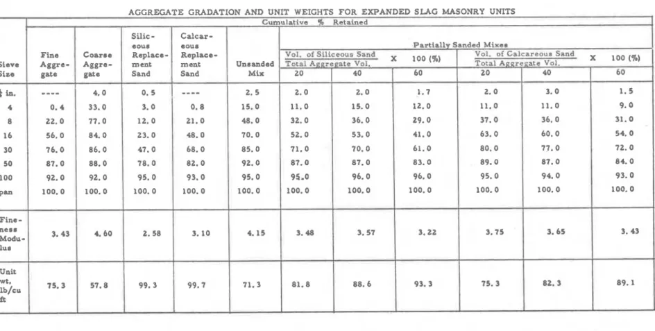
cia1 grade w e r e employed for expanded slag and expanded shale a g g r e - gates, while grading of l a r g e r expanded clay particles was described a s medium. Pumice units were produced with m a t e r i a l of the fine fraction only. Gradation of siliceous and calcareous replacement m a t e r i a l s f o r sanded units was generally fine.Typical gradings, unit weight and fineness moduli of aggregates a r e presented in Appendix A; data a r e a l s o given for combined gradations of lightweight aggregate fractions as well as for partially sanded mixtures.
Mortar for construction of t e s t panels conformed t o the r e q u i r e - ments of ASTM Designation C270. Type N masonry m o r t a r approximately
3/8 in. thick was mixed from recommended proportions of type H masonry
cement and damp loose aggregate. Mortar samples w e r e taken at frequent
intervals during construction and allowed t o c u r e in an atmosphere of 95
t o 100 p e r cent relative humidity at a t e m p e r a t u r e of 73°F. After 28 days,
samples w e r e removed from the curing chamber and tested in compression.
Strengths w e r e usually found t o be well above the minimum p e r m i s s i b l e level of 750 p s i for type N m o r t a r .
Concrete Masonry Units
To e n s u r e some degree of uniformity in m i x designs, an aggregate- cement r a t i o (by volume) of 1:8 was specified for expanded slag, expanded shale, and expanded clay aggregate units. F o r pumice units, the r a t i o
selected was 1:6 (by volume). These were intended primarily to control
strength levels of the different units. Cement contents ( p e r unit volume of concrete) w e r e kept constant for both pure and sanded mixtures of a given lightweight aggregate group. Mix data, unit green weights and the yield ( p e r batch of concrete) f o r units a r e presented in Table 2.
Masonry units w e r e low p r e s s u r e cured, although curing techniques varied among individual producers. Expanded slag units w e r e allowed a p r e s e t period of 2 h r followed by a 1 -hr steam period a t
1 2 0 ° F and 4 h r a t 165°F. Units w e r e then soaked for 7 h r at 140°F. Expanded shale uliits w e r e allowed t o p r e s e t for 2 h r . Maximum kiln temperature reached in 4 h r was 160" F with a 2 -hr hold *eriod. Soak period was 16 h r giving a total c u r e cycle of 24 h r . For expanded clay units, p r e s e t period was 4 h r a t a temperature of 100°F. Units w e r e steamed for 1 h r at 1 3 5 ° F and 4 h r at 180°F. The t e m p e r a t u r e in the kiln was then.10wered t o 1 4 0 ° F where units were allowed t o soak f o r 4 h r . After an initial p r e s e t period of 4 h r , pumice units w e r e steamed for
3 h r and allowed t o soak:for a n additional 16 hr. Maximum kiln t e m p e r a - t u r e reached during the ateam period was 173°F.
After initial steam curing, units w e r e exposed t o normal atmospheric conditions for approximately 30 days. Five units each of the 28 different types in the p r o g r a m w e r e then selected for determination of various physical properties, i. e. strength, density, absorption, porosity and
specific gravity. Physical property data for units of the four lightweight aggregate groups a r e presented in Tables 3 through 6.
TESTING PROCEDURE
Conditioning of Specimens
F i r e t e s t specimens w e r e constructed with units having aged between 1 and 2 months. After construction the relative humidity in the p o r e s of the masonry units was measured at regular intervals t o d e t e r - mine their suitability for f i r e testing in accordance with ASTM E119-- Standard Methods of F i r e T e s t s of Building Construction and Materials
(7).
The p r e s c r i b e d moisture condition within the specimen i s considered as that which would be established at equilibrium resulting from drying in an ambient atmosphere of 50 p e r cent relative humidity at 73°F. Alternatively, where it may be difficult o r impossible t o achieve such uniformity within a reasonable period of time, specimens may be tested when the dampest portion of the s t r u c t u r e has achieved a m o i s t u r e content corresponding t o drying t o equilibrium with air in the range of
50 t o 75 p e r cent relative humidity a t 73&5" F. In this program, specimens w e r e deemed suitable for testing in accordance with the second criterion.
Relative humidity levels within the specimens w e r e measured by means of an El-Tronics portable hygrometer. Cylindrical samples, approximately 1.80 in. in length w e r e cut f r o m specimens n e a r mid- sections of the units. Each sample was subsequently divided into t h r e e pieces, crushed and the moisture levels determined. Holes left in the
masonry work after removal of the sample were filled with fast-setting high-temperature m o r t a r .
Specimens made with pumice aggregate units generally retained high moisture levels longer than those made with expanded slag, shale o r clay aggregates. As artificial drying of f i r e t e s t specimens i s
permitted, provided no abnormal changes a r e brought about in s t r u c t u r a l properties, t h e s e specimens w e r e subjected t o uniform accelerated
drying at a t e m p e r a t u r e of 105°F. This temperature was considered sufficiently low s o as not t o induce any physio-chemical changes in the s t r u c t u r e of the concrete and accelerated the development of acceptable moisture levels.
F i r e T e s t s
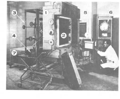
All specimens w e r e tested in the s m a l l - s c a l e f i r e t e s t assembly
shown in Figure 2. The furnace i s built mainly from insulating f i r e
brick and high t e m p e r a t u r e m o r t a r . It has a n opening of 29$ in. by 31 in. and can accommodate specimens approximately 32 in. square.
Heat i s supplied t o the furnace chamber through twelve Globar
silicon carbide heating elements of
2
in. diameter, 34 in. effectivelength and 54 in. over-all length. An Inconel plate 29 in. by 30 in. by 5/8 in. protects the heating elements f r o m possible shocks caused by spalling of specimens and at the s a m e time s e r v e s a s a heat exchanger.
The t e m p e r a t u r e of the furnace is measured by five B and S gauge 16, Chromel-Alumel Cerarno -type thermocouples. Each of the five
t e m p e r a t u r e s , a s well a s their average, a r e recorded on a potentiometric multipoint temperature r e c o r d e r . Heat input into the furnace is
programmed t o follow the standard time-temperature curve prescribed by ASTM E l 1 9 (Figure 3).
Temperatures on the unexposed surface of specimens w e r e measured by t h r e e thermocouples placed under standard asbestos pads approximately 6 in. square. One was located a t the c e n t r e of the specimen and two along a diagonal from left t o right. Two additional thermocouples were used t o record temperatures on the unexposed 'true' surface* but these t e m p e r a t u r e s w e r e not used t o determine when ::: Simultaneous measurements of the t r u e surface t e m p e r a t u r e ( t h e r m o - couple junctions a r e exposed t o the surrounding a i r ) and the standard s u r
-
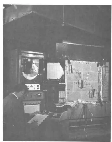
face t e m p e r a t u r e (asbestos pads a r e placed over thermocouple junctions) indicate that when the standard surface t e m p e r a t u r e increased by 250" F the t r u e surface temperature, was on an average, only 1 6 0 ° F above the initial value. However, since the heat flow pattern in the vicinity of the asbestos pads i s t h r e e dimensional and may be substantially different f r o m the prevailing pattern, it i s difficult t o c o r r e l a t e the standard s u r f a c e t e m p e r a t u r e with the t r u e surface temperature, especially in a transient process, which is invariably the c a s e in a simulated f i r e exposure.an end point in the t e s t had been reached. Figure 4 shows a typical t e s t in progress.
As a m a t t e r of interest, in one of the t e s t s the t e m p e r a t u r e distribution during heating between the exposed and unexposed face was a l s o studied. Two additional thermocouples, one at a depth of one third the distance between the exposed and unexposed f a c e and the other at a depth of two t h i r d s this distance, w e r e inserted t o
r e c o r d t e m p e r a t u r e s at intermediate levels within the specimen during f i r e exposure. After t h e f i r e endurance period had been exceeded, the furnace was shut down and the t e m p e r a t u r e distribution within the specimen was recorded during the cooling period as well.
OBSERVATIONS AND RESULTS
Tables 7 through 10 respectively show r e s u l t s of f i r e endurance t e s t s on panels made with expanded slag, expanded shale, expanded clay and pumice aggregate units. When tested, specimens had aged between 104 and 266 days. Maximum measured equilibrium relative humidity within units varied between 55 and 75 p e r cent. Equivalent thickness(8) of masonry panels* shown in the tables ranged from 3. 37 in. f o r
unsanded expanded shale units t o 3.64 in. for heavily sanded expanded slag units.
In each test, f i r e endurance periods w e r e determined by average t e m p e r a t u r e r i s e on the unexposed surface exceeding 250°F above ambient r a t h e r than by excessive t e m p e r a t u r e r i s e a t any one of the measured points. T e m p e r a t u r e s recorded during the t e s t of t h e specimen having additional thermocouples at intermediate depths f r o m the exposed surface a r e shown in Figure 5. The f i r e endurance of the specimen was reached a t 2 h r 21 min. due t o the average r i s e of t e m p e r a t u r e on the unexposed surface exceeding 326" F (250" above ambient). The furnace was shut down a t 150 rnin., while t e m p e r a t u r e measurements of the specimen continued for an additional 150 min.
As expected, the average t e m p e r a t u r e on the unexposed surface continued t o r i s e , reaching i t s maximum value a t about 250 min. and then began t o d e c r e a s e a t a f a i r l y uniform rate. Temperatures at intermediate depths from the exposed surface a l s o continued t o i n c r e a s e after 150 min. although the t i m e required t o r e a c h a maximum level decreased with proximity t o the fire-exposed surface.
-
4 Equivalent thickness values w e r e determined on the basis of average net a r e a in accordance with the procedures outlined in ASTM C 140-65T.
Specimens w e r e not loaded during the t e s t s and w e r e virtually unrestrained on both the horizontal and vertical edges. Owing t o t h e i r s m a l l size, tbowing' of specimens towards the f i r e exposure a s a
result of differential expansion induced by rapid heating was not detected.
Observations made on specimens during the t e s t s a r e summarized in Table 11.
DLSCUSSION
F i r e Endurance of Sanded Lightweight Aggregate Masonry Units
The effect of increasing amounts of sand replacement on the f i r e endurance of lightweight aggregate masonry units i s evident f r o m Tables 7 through 10. The f i r e endurance of panels decreased a s the amount of sand expressed as a percentage of the total aggregate volume in the units increased. F o r completely lightweight units made with expanded slag, expanded shale, expanded clay and pumice aggregates, f i r e endurance periods w e r e 2 . 2 3 h r , 2.01 h r , 2.52 h r and 2.83 h r respectively. When approximately 60 p e r cent of the lightweight
aggregate in the units was replaced with siliceous sand, t h e s e periods w e r e reduced t o 1.65 h r , 1.72 h r , 1.88 h r and 1.79 h r respectively. Corresponding f i r e endurance periods when calcareous sand was substituted f o r approximately 60 p e r cent of the lightweight m a t e r i a l w e r e 1.60 h r , 1. 52 h r , 1.88 h r and 2. 20 h r respectively.
In Figure 6, the f i r e endurance of sanded lightweight aggregate masonry units i s plotted a s a function of the amount of sand replacement, expressed as the r a t i o of the volume of sand t o the total aggregate
volume. F i r e endurance periods of p u r e (unsanded) units of each of the four lightweight aggregates a r e shown a s well a s r e s u l t s of t e s t s on units made entirely with siliceous and calcareous sand, i. e. (volume of sand)
/
(total aggregate volume) = 1. The l a t t e r t e s t s w e r e c a r r i e d out during an e a r l i e r study(6) and additional details a r e given in Table 12.F i r e endurance was assumed t o d e c r e a s e linearly with increasing amounts of sand substitution, and 'lines of best fit' w e r e determined f r o m the data. These a r e shown in Figure 6 for each of the four types of
lightweight aggregates. Equations of the lines of best f i t a r e given in Table 1 3 where they have been used t o determine the percentage d e c r e a s e in f i r e endurance of sanded units relative t o unsanded units f o r typical amounts of sand replacement.
The maximum amount of sand replacement generally accepted by most block manufacturers is 20 p e r cent. F o r this amount of
sand substitution Table 13 indicates that the f i r e endurance of sanded units will be approximately 5 t o 9 p e r cent lower than that of the p u r e (uns anded) unit depending upon the particular lightweight a g g r e g a t e selected.
At a given level of sand replacement, the resulting d e c r e a s e in f i r e endurance for sanded units was generally of the s a m e o r d e r of magnitude for both types of replacement sand. The notable exception t o this behaviour was observed for heavily sanded pumice aggregate units in which substitution of siliceous replacement sand for pumice
aggregate resulted in correspondingly g r e a t e r d e c r e a s e s in f i r e endurance than when calcareous replacement sand was used ( F i g u r e 6).
Lightweight masonry units with natural sand replacement would be expected t o exhibit t h e r m a l c h a r a c t e r i s t i c s between those of
lightweight and normal weight units. As aggregates comprise about 7 5 p e r cent of the total concrete volume, it i s p r i m a r i l y t h e i r t h e r m a l and mineralogical properties that will determine performance of t h e concrete in fire.
Lightweight aggregates exhibit better t h e r m a l behaviour than n o r m a l weight aggregates. Their stability a t high t e m p e r a t u r e s i s p r i m a r i l y due t o the fact that during their manufacture most light- weight aggregates have been subjected t o t e m p e r a t u r e s s i m i l a r t o those
experienced in f i r e t e s t s . The porous s t r u c t u r e of t h e s e aggregates offers good r e s i s t a n c e t o heat flow through radiation, the p r i m a r y mechanism of heat t r a n s f e r in concrete at high temperatures. The t h e r m a l conductivity of lightweight concretes is low, typically 0. 2 t o
0. 4 Btu/hr ft O F at room temperature. At elevated t e m p e r a t u r e s ,
the t h e r m a l conductivity i n c r e a s e s slowly and above 1400"
F,
0. 35 ~ t u / h r f t " F i s a typical value.The t h e r m a l conductivity of concretes made with normal weight aggregates may v a r y from 0.7 Btu/hr ft OF t o a s high a s 1 . 5 ~ t u / h r f t " F. With increasing temperatures, their conductivity d e c r e a s e s and above 1400°F, most normal weight concretes exhibit t h e r m a l conductivities
between 0.7 and 0.8 Btu/hr ft
OF.
When natural sand is used in combination with lightweight a g g r e - gate, the effective t h e r m a l conductivity of the concrete will be related t o the t h e r m a l conductivities of the two aggregates and the volume
concentration and distribution of each within the aggregate matrix. Since the conductivity of the lightweight aggregate i s lower than that of sand, the effective t h e r m a l conductivity of the aggregate mixture f o r sanded lightweight units will i n c r e a s e a s the percentage of sand in the
total aggregate volume increases. The t h e r m a l f i r e endurance of lightweight aggregate masonry units would, therefore, be expected to d e c r e a s e when portions of the lightweight m a t e r i a l a r e replaced with natural sand.
Effect of Sand Replacement on O t h e r Physical P r o p e r t i e s
Other properties of lightweight masonry units having various amounts of sand replacement a r e of interest to producers.
Water absorption of lightweight units decreased significantly with increasing amounts of sand substitution. At the 20 p e r cent
replacement level, this d e c r e a s e was most notable for pumice aggregate units. Water absorption for unsanded pumice units was 26.9 p e r cent, while approximately 20 p e r cent replacement with siliceous and calcareous
sand reduced absorption t o 21. 4 and 20. 3 p e r cent respectively. At
this level of replacement, expanded shale and expanded clay aggregates generally showed the lowest reduction in water absorption.
The effect of sand replacement on the compressive strength
of lightweight aggregate masonry units is shown in Figure 7. Strengths
for both pure lightweight and sanded units w e r e determined from specimens which had aged between 91 and 110 days. T h e r e did not appear t o be a consistent relationship between the amount of sand replacement and the resultant change in compressive strength. As indicated by the band (Figure 7), compressive strengths generally increased for sanded units in which up t o 60 p e r cent by volume of the lightweight m a t e r i a l was replaced with natural sand. The effect
of l a r g e r amounts of sand substitution on compressive strength, i. e.
,
(0. 6 <(Val. of s a n d ) / ( ~ o t a l aggregate volume) < 1. O), cannot be
determined from the data.
The effect of sand replacement on the density of units made with
a particular lightweight aggregate was much m o r e evident. In Figure 8,
the density of units made with each of the four lightweight aggregates i s shown a s a function of the amount of sand replacement. Lines of best fit w e r e determined from the data and these a r e shown in Figure 8 f o r each of the four types of lightweight aggregates. Equations of the lines of best fit a r e given in Table 1 3 where they have been used t o determine the percentage i n c r e a s e in density of sanded units relative t o unsanded units for typical amounts of sand replacement. At the 20 p e r cent replacement level, Table 1 4 indicates that the density of sanded units
will be approximately 5 to 13 p e r cent higher than that of the pure
(unsanded) unit depending upon the particular lightweight aggregate selected.
It should be noted thak the reported data may not be r e p r e s e n t a -
tive for all aggregates of a particular type, since concretes containing
apparently s i m i l a r aggregates may exhibit a wide range of properties.
Within limits, however, the equations in Tables 1 3 and 14 may be
useful in estimating both the f i r e endurance and density of a given
lightweight aggregate unit for a particular level of sand replacement.
C ONC LUSIONS
Several conclusions seem warranted, based on r e s u l t s of the 28 small-scale f i r e tests. It should be noted, however, that these results were obtained from the specific m a t e r i a l s selected for u s e in this study.
1. Sand replacement in lightweight aggregate masonry units d e c r e a s e s f i r e endurance in proportion to the amount of lightweight m a t e r i a l
replaced. Generally, the f i r e endurance of a sanded unit relative t o
that of the unsanded unit for a particular lightweight aggregate decreased
linearly with an increase in the ratio (volume of sand)/(total aggregate
volume)
.
2 . The higher the f i r e endurance of the unsanded (all-iightweight) unit, the greater was the reduction in f i r e endurance a t a given level of sand
r eplac em ent.
3. In general, the reduction in f i r e endurance at a given level of sand replacement was not dependent upon the type of replacement sand used.
4. F o r sand replacement levels characteristic of current production
practice, the decrease in f i r e endurance of lightweight masonry units due t o sand substitution is not excessive. At 20 p e r cent replacement, by volume, the d e c r e a s e in f i r e endurance of sanded units made with expanded slag, expanded shale, expanded clay and pumice aggregate
units respectively was 7.73, 5.09, 8. 19 and 9.06 p e r cent.
ACKNOWLEDGEMENTS
The author would like to acknowledge the assistance and co- operation provided by D. S h e a r e r and other staff members of the F i r e Research Section.
These t e s t s , conducted in the NRC F i r e Research Laboratory, were part of a program of r e s e a r c h , under the cooperative r e s e a r c h fellowship arrangement between the National Concrete Producers'
Association and the National Research Council of Canada. The support
provided by t h e Portland Cement Association is also gratefully
REFERENCES
Hanson, J. J. Replacement of Lightweight Aggregate F i n e s With N a t u r a l Sand i n S t r u c t u r a l Concrete. ACI Journal, P r o c e e d i n g s Vol. 61, No. 7, July 1964, p. 779-793; P C A Development Department Bulletin D80.
Pf e i f e r , D. W. and Hanson, J. A. Sand Replacement i n S t r u c t u r a l Lightweight C o n c r e t e --Sintering G r a d e Aggregates, ACI Journal, P r o c e e d i n g s , Vol. 64, No. 3, M a r c h 1967, p. 121 -127; P C A Development Department Bulletin Dl 15.
P f e i f e r , D. W. Sand Replacement in S t r u c t u r a l Lightweight C o n c r e t e
-
-Splitting T e n s i l e Strength. ACI Journal, P r o c e e d-
ings, Vol. 64, No. 7, J u l y 1967, p. 384-392; Development Department Bulletin D l 20.P f e i f e r , D. W. Sand Replacement i n S t r u c t u r a l Lightweight C o n c r e t e - - F r e e z i n g and Thawing T e s t s , ACI Journal,
P r o c e e d i n g s , Vol. 64, No. 11, Nov. 1967, p. 735-744; P C A Development Department Bulletin Dl 26.
Pf e i f e r , D. W. Sand Replacement i n S t r u c t u r a l Lightweight C o n c r e t e - - C r e e p and Shrinkage Studies. ACI Journal, P r o c e e d i n g s , Vol. 65, No. 2, F e b r u a r y 1968, p. 131-139. Allen, L. W. F i r e Endurance of Selected Non-Loadbearing C o n c r e t e M a s o n r y Walls. National R e s e a r c h Council of Canada, Division of Building R e s e a r c h . F i r e Study No. 25, Ottawa, M a r c h 1970, NRC 11275.
Standard Methods of F i r e T e s t s of Building Construction and M a t e r i a l s . ASTM Designation E l 19 -69, A m e r i c a n Society f o r T e s t i n g and M a t e r i a l s , Philadelphia, Pa.
Tentative Methods of Sampling and T e s t i n g C o n c r e t e M a s o n r y Units, ASTM Designation C 140 -65T, A m e r i c a n Society f o r T e s t i n g and M a t e r i a l s , Philadelphia, Pa.
T A B L E 1
F I R E ENDURANCE TESTS ON P A N E L S MADE WTIH LIGHTWEIGHT AGGREGATE MASONRY UNITS
D e t a i l s of M a s o n r y P a n e l s F i r e T e s t P a n e l N u m b e r
Type of
Appr oxirnate V o l u m e R e
-
Replace -placement af Lightweight ment Sand P u m i c e
Aggregate i n U n i t s , '$0 U s e d 0 none 1 2 3 4 20 s i l i c e o u s 5 6 7 8 40 s i l i c e o u s 9 1 0 11 1 2 60 siliceous 1 3 1 4 1 5 1 6 2 0 40 60 c a I c a r e o u s c a l c a r e o u s c a l c a r e o u s 17 21 25 1 8 2 2 26 1 9 23 27 20 2 4 28
T A B L E 2
MIX PROPORTIONS F O R CONCRETE MASONRY UNITS
Unit G r e e n Weight (lb) 26. 6 28. 4 29. 7 30. 4 27. 8 29. 6 30. 3 A g g r e g a t e Type Expanded S l a g Expanded Shale Expanded C l a y P u m i c e A c t u a l Percent Replacement o f Lightweight Aggregate with N a t u r a l Sand ( b y Vol. ) 0 21. 6 42. 0 61. 8 20. 7 40. 6 60. 4 0 19. 5 39. 3 59. 5 18. 7 37. 6 58. 3 0 20. 4 40. 6 60. 6 20. 2 40. 4 60. 4 0 18. 0 36. 7 56. 8 19. 0 38. 3 58. 4 Yield p e r Batch of C o n c r e t e 81. 0 81. 5 83. 0 85. 5 81. 0 82. 5 78. 0 C e m e n t (lb) 320 320 320 320 320 320 320 42 8 42 8 428 428 42 8 42 8 428 641 641 641 6 41 641 641 6 41 320 Q u a n t i t i e s p e r B a t c h of C o n c r e t e F i n e 1380 980 600 205 980 600 205 126. 5 1 2 4 . 0 1 2 1 . 0 1 1 8 . 0 114. 0 118. 5 1 1 7 . 0 1 6 8 . 0 1 6 8 . 0 1 6 8 . 0 1 6 8 . 0 1 6 8 . 0 1 6 8 . 0 1 6 8 . 0 63. 0 63. 0 63. 0 63. 0 63. 0 63. 0 65. 0 1700 1290 873 46 1 1290 873 46 1 968 776 580 390 776 580 390 1135 20. 9 23. 0 26. 0 28. 9 24. 6 25. 8 28. 3
---
---
---
- - -
---
- -
-
- - -
22. 1 24. 9 27. 2 28. 8 24. 5 25. 0 28. 2 A i r D r y A g g r e g a t e , (lb) C o a r s e 320 320 320 320 320 320 !---
- - -
---
---
706 1380 21 20 I-
- -
---
- - -
---
---
---
---
I 300 300 300 300 300 300 300 2360 905 680 450 905 680 450 S i l i c e o u s Sand-
--
7 45 1490 2230-
-
-
- -
-
---
---
C a l c a r e o u s Sand 1890 141 0 9 40 1890 1410 9 40---
350 695 1040---
- - -
- -
-
---
---
---
---
555 1100 1650 47 0 47 0 47 0 47 0 47 0 47 0 47 0- - -
---
---
360 715 1070---
580 1160 17 40---
---
---
1010 2020 3031-
-
-
---
---
---
---
- - -
1010 2020 3031---
- - -
2 L-l . d
;
5>
I3 0 r - N * O 0 0 0 0 0 O O Q ) m m a a m 0. .
9 N m ao ma^. .
9 " i c r ; r - ' 0 o r - r; 6 i r c m d N' r( m 0 ' - d-
* *
0 rr d m r- o o m 0 o o 0 0 0 0 0 0 3 Q) 9 9 9 m o m o o' 9 N W N m " i & G G 0 4 i i "i G G 0 ni d N 9 d r l d m o ' 9 d 4 m m o o * 0 0 0 o o 0 0 0 - 1 m 9 9 9. . . .
d o c o m m 0 V Q ) ~Ul m m t - a o dad r-' o; cd G o d o ni A N P O o d m rn N r( r( m u w r- '-0 rn 0 ' N r - 0 o o 0 0 0 O O N 0-,q
.s m a a o ' 0. . 0 9*
9 *..
~ mm m C " i & G "i O N r- d 0 m m o nis 3
dz 0
*
-
NTABLE 4
PHYSICAL PROPERTIES OF EXPANDED SHALE AGGREGATE MASONRY UNITS
- -
I
1
Partially Sanded UnitsProperty Unsanded Vol. of Siliceous Sand Vol. of Calcareous Sand
Units Total Aggregate Vol. Total Aggregate Vol.
x
loo(%)Dimensians : Length, in. W i d t h , in. Depth, in. Received weight, lb
I
21.00Compreesive strength, psi 2780.00
I
Density, lb/cu ft
1
86.10Bulk density (oven dry
condition) lb/cu ft 79.40 Water absorption, lb/eu f t W a t e r absorption, yo ( 2 -hr boiling) Moisture content as 70 total absorption
1
33. 30Average net area, 70 Apparent poroaity
Apparent specific gravity
Each figure represents average of five tests.
Compressive strengths were determined 91 days after casting.
9 9 m c r 0 0 0 0 0 0 m 9 m 9 0 d QI 0' m Od Oa Nmd 9' " i " i G G 0 & d 9' N w " i r - ' d h i N 9 0 0 r( r( d m cr 0 d m 9 V I O l n 0 0 0 0 0 0 0 o m d m s m 01
. . .
.
0 9 0 r- 0 v m m.
m.
m m r - 9 d d d m N d d N 2 2 0 d N G % O N m 2 5 4 .d 9 c .; 0 m 9 - n N O 0 d 0 0 0 9 0 0 m 0 m 0 rrl 0 0 9 C O 3 ;g N I - c r m d "in'm'cc' u; d r-';
> b d 'I- m P i d G d n ; N - O l 0' d N d 01 v Ol 0 N d m -*
4 4 d-
a)z
E
o
9 9 9 o o m 0 In 0 0 0 0 0 0 9 0 \O 0 0 0 0 1 9 9.
. .
m N N m2
m m r cw
d r; d N 9' d d d r. i G 0 h i d N r n . 4 m cr cr d 4 N I- 9 d ' O 0 0 0 0 0 0 O O r . 0 ' m a 9. . .
N 0 9 N 9 m d.
. . .
m m r - r- d 9' 9 ' 0 0 0 N N-
0 m cr CO d d N CO I - m h l 0 0 0 0 0 0 o o m m m 9 . n m 0 d m 9 m d "i"icc' "i d d d ad 0 n; N c r O V l cr CO d N v N d d d 0 0 0 0 0 0 O O P -a 9 9. . .
00 0 0 0 d 0' ~ o , m % Z f i-
' 6. . .
m m r - i d d d d d & 0 0 9 0 N N N cr 01 N m 01 0 m -.4 m a u*
w & c 0 . 4 w2
u k e d d h d 'CI ti2
CI m d 2 v e;
.5 W k:;
M7;12
:
5 3 h u Q) a 0 k 01<
2
s
'm 0 s m ss 2 c m - : Eg *
;Ez
z c
j
.g
*T,,
m,
2 :
2
.d m2
c . . .* -=-. p yhz-
:.22
:
.
O Xe
o,
",
d '-4 0 0 U h C A $ u '" wz?
JI m i a " " u : r r ; d . 2 r d ; r a w:<
w5
5 . 5
5 .fl - 5 fl, U o E N :k: 2 - u h rb ~ 4 3 ~ 3 8a -
m ,P .4 na
ad G 2 2 E 3
34
e P) k k @: h et . 2
1:2:
. E $
2 4 6
TABLE 6
PHYSICAL PROPERTIES O F PUMICE AGGREGATE MASONRY UNITS
Property Length, in. Width, in, Depth, in. Unsanded Units Received weight, lb Compressive strength, p s i
Vol. of Siliceous Sand
x
l o o (%)
Total Aggregate Vol.
Density, Ib/cu ft
Vol. of Calcareous Sand
Total Aggregate Vol. X 100 (70)
Bulk density (oven d r y condition) lb/eu ft Water absorption, ~ b / c u f t W a t e r absorption, YQ ( 2 -hr boiling) Moisture content a s 70 total absorption Average net area, %
Apparent poroeity Apparent specific gravity
I I
I
Each figure represents average of five t e s t s .
TABLE 7
RESULTS O F FIRE ENDURANCE TESTS ON EXPANDED SLAG AGGREGATE MASONRY UNITS
T e s t NO. 1 5 9 13 17 2 1 2 5 C Details of T e s t Panel Equivalent Thickness of Units, in. 3. 46 3 . 5 6 3. 57 3 . 6 0 3 . 5 3 3 . 5 9 3. 64 VoIume Replace- ment of Light- weight Agg. in Units, X 0 2 1 . 6 42.0 61.8' 20.7 40.6 60. 4 Type of Re- placement Sand none siliceous siliceous siliceous calcareous calcareous calcareous Maximum Equilibrium Relative Humidity In Units, O/o 7 5 75 Age of Units when tested, days 2 32 183 F i r e Endur
-
ance, 4 h r 2. 23 2.15 68 68 58 6 6 66 F a i l u r e C r i t e r i a Av. r i s e of temp. Av. r i s e of temp. 1 . 8 4 1. 65 2. 1 3 1.83 1. 60 104 105 175 132 126 Av. r i s e of temp. Av. r i s e of temp. Av. r i s e of temp. Av. r i s e of temp. Av. r i s e of temp.TABLE 8
RESULTS OF FIRE ENDURANCE TESTS ON EXPANDED SHALE AGGREGATE MASONRY UNITS
Failure Criteria Age of Units when tested, days Maximum Equilibrium Relative Humidity in Units, %
-
-
-
-F i r e Endur-
ance; h r I Equivalent Thickness of Units, in. r Teat NO. 69 7 0 207 2 46 3.37 3. 45 2' 6Details of Teet Panel
Volume Replace- ment of Light- weight Agg. in U n i t s , % 2.01 1.85 3 . 5 4 3.58 3. 45 3.42 3. 55 10 14 18 2 2 2 6 Type of Re- placement Sand 0 19.5 Av. r i s e of temp. none
eiliceoue Av. r i s e of temp.
61 5 5 5 5 7 0 7 4 39.3 123 124 144 160 174 1.78 1.72 1.85 1.73 1.62
eiliceoue Av. r i s e of temp.
Av. r i s e of temp. Av. r i s e of temp. Av. r i s e of temp. Av. r i s e of temp. 59.5 18.7 37.6 58. 3 siliceous calcareous calcar eoue calcareous
TABLE 9
RESULTS O F FIRE ENDURANCE TESTS ON EXPANDED CLAY AGGREGATE MASONRY UNITS
Details of T e s t Panel Equivalent Thickness of Units, in. 3. 52 Type of Re- placement Sand none siliceous siliceous siliceous calcareous calcareous calcareous Volume Replace- ment of Light- weight Agg. in Maximum Equilibrium Relative Humidity in Units, O/o 70 7 11 15 19 2 3 27 20. 4 40.6 60.6 20.2 40. 4 60. 4 Age of 3. 58 F i r e I 73 266 Av. r i s e of temp. Av. r i s e of temp. Av. r i s e of temp. Av. r i s e of temp. Av. r i s e of temp. Av. r i s e of temp. 3. 59 3. 57 3. 60 3.57 3. 5 4 2 . 2 8 F a i l u r e C r i t e r i a Units when Tested, Days Endur
-
ance, h r 6 4 7 2 73 60 75 Av. r i s e of temp. 2 57 254 264 216 132 265 2. 52 2. 04 1.88 2. 26 2. 06 1.880 0 0 C I u + ) C ) C I C I W W W W W W 0 0 0 0 0 0 S S S S S S 4 4 4 4 4 4 N I C r n l n h O * N r - c r ) . o N N ' N ' L N ' N ' N ' % i 2 % % 3 g N d N N d N m - M m . o * m . o . o l n m m c c ; c ; A n ; A * i * , , . o o * a 4 M N N N
TABLE 11
SUMMARY O F OBSERVATIONS DURING FIRE TESTS
Observations
30 m i n
-
steam expelled from unexposed surface of u n i t s ; rid physical d i s r r ~ p t i o n of specimend u r i n g t e s t
32 m i n - f o r m a t i v of m o i s t u r e beads on units near m o r t a r joints
40 rnin
-
steam expe!led f r o m units ; no physical disruption30 m i n
-
smalI quantities of moisture c o l l e c t e d on 2 vertical m o r t a r joints35 mil&
-
l in. crack develops In vertical mortar jnint37 rnin
-
steam expelled [ram unrts60 rnin
-
crack erctends to almost full height of v e r t i c a l joint30 m i n
-
minute quantities of maisture coHected at m o r t a r joints; s t e a m expelled from units;no physical Jis ruption
25 m i n
-
minute quantities of m o i s t u r e collected at m o r t a r joints 30 rnin-
steam expelled p e r i o d i c a l l y u n t i l 47 min. into t e s t40
-
45 mrn-
hairline d i a g o n a l cracks, 3 in. and 7 in. in length developed in 2 units 45-
60 min - hairline cracking developed over Eull h e i g h t of 2 vertical m o r t a r joints2 4 min
-
minute quantities of m o i s t u r e collected at m o r t a r joints 30 rnin-
s t e a m ehielied from units25
-
35 min - vertical and horizontal hairline cracks 3 in.-
7 in. in length developed over2 unlts and 5 mortar joints
30 min
-
s t e a m expelled from units60 rnin
-
vertical crack devcloped at midpoint of specimen extending from top t o bottom ofmasonry p a n e l
I---- --- -
2 5 min
-
s t e a m expelled from units; n o physical disruption30 min
-
steam expelled f r o m u n i t e ; no physical disruption20 - 40 m i n
-
horizontal and vertical cracks, approx. 7 in. i n length developed along4 m o r t a r joints
27
-
30 rnin-
small quantities of m o i s t u r e collected above initial c r a c k s30
-
40 rnin-
s t e a m expelled through c r a c k s20
-
25 min-
formation of m o i s t u r e beads along 3 in. of one horizontal and one v e r t i c a l m o r t a r joint30 rnin
-
three hairline cracks approx. 7 in.. 3 i n . , and 2$ in. in length developed alongt w o vertical m a r t a r joints 35 m i n
-
steam expelled from units2 4 m i n
-
minute quantities of m o i s t u r e collected on s u r f a c e s of two units adjacent m o r t a rjointa. I F i r e T e s t Specimens Expanded Slag Aggregate Units - - - T e s t NO. 1 5 9 13 17 2 1 25 1 2 Expanded Shale Aggregate 6 10 1 4 18
T A B L E 1 3
DECREASE IN F I R E
ENDURANCE
O F LIGHTWEIGHT AGGREGATE MASONRY UNITS F O R T Y P I C A L AMOUNTS O F SANDREP
LACEMENT*Equations of t h e f o r m y = a
+
bx w h e r e y = f i r e e n d u r a n c e , and x = (vol. of s a n d )/
( t o t a la g g r e g a t e vol. ) w e r e developed f r o m f i r e t e s t d a t a on s p e c i m e n s and u s e d t o d e r i v e t h e f i g u r e s shown. Type of Light- weight A g g r e - gate Unit Expanded S l a g Expanded S h a l e Expanded C l a y P u m i c e Empirical Equation t o Express Relationship between Fire E n d u r a n c e and S a n d Replacement* y = 2 . 2 4
-
0 . 8 6 6 ~ y = 1 . 9 6-
0. 499x y = 2 . 4 9-
1 . 0 2 ~ y = 2 . 7 6-
1 . 2 5 ~ P e r c e n t a g e Decrease in Fire E n d u r a n c e ofSanded Units Relative to Unsanded V n i t s
for Typical Amounts of Sand R e p l a c e m e n t 2070 7 . 7 3 5. 09 8. 1 9 9. 06 40
70
I
60% 1 5 . 4 6 1 0 . 1 8 1 6 . 3 8 1 8 . 1 2 2 3 . 2 0 1 5 . 2 7 2 4 . 5 8 27.17TABLE
14INCREASE IN DENSITY O F LIGHT'CVEIGHT AGGREGATE MASONRY UNITS
FOR
TYPICAL
AMOUNTS O F SAND R E P LACEMENTType of Light
-
weight Aggregate Unit Expanded Slag Expanded Shale Expanded Clay P u m i c e*
Equations of the f o r m y=
a+
bx w h e r e y=
unit density and x = ( v o l . of sand)/
(totala g g r e g a t e vol. ) w e r e determined f r o m the data and used t o d e r i v e f i g u r e s shown.
E m p i r i c a l Equation t o
Express Relationship
between Dens it y and
Sand Replacement tC
y = 102.1
+
2 6 . 7 ~y
=
85. 1+
4 3 . 5 ~y = 91.9
+
3 3 . 8 ~y = 78. 4
+
5 0 . 4 ~P e r c e n t a g e Increase in Density of Sanded Units
Relative t o U n s a n d e d Units f o r Typical Amounts
of Sand Replacement 2070 I 40 % 60% 15.69 30.67 22.07 38. 57 5. 23 10.22 7.35 12.86 10. 46 20.45 14.71 25.71
Figure 2 . Small-scale Fire Test Assembly.
1. Electric test furnace. 2. Inconel plate.
3. Equipment for air supply control. 4. Oxygen analyzer.
5. Multipoint temperature recorder.
6. Temperature controller -recorder. 7. Saturable core reactor.
T I M E , H O U R S
A S T M C U R V E
800
k
I111
600
--
F I G U R E
3
S T A N D A R D T I M E
-
T E M P E R A T U R E C U R V E
400
I-
-
200
0
-
+ I 1 I I II
11
2
3
4
5
6
7
8
E X P A N D E D SLAG U N l T S
- ---
E X P A N D E D SHALE U N I T S---
E X P A N D E D C L A Y U N I T S-..-
P U M I C E U N I T S V O L U M E O F S A N D W er-
L 1.0 -c- T O T A L A G G R E G A T E V O L U M E 0 S I L I C E O U S REPLACEMENT S A N D-
- CALCAREOUS REPLACEMENT S A N D X PURE L I G H T W E I G H T OR PURE S A N D U N I T T -I
I
F I G U R E 6 E F F E C T O F S A N D R E P L A C E M E N T O N F I R E E N D U R A N C E O F ( S O L I D 4" N O M I N A L ) L I G H T W E I G H T A G G R E G A T E M A S O N R Y U N I T S r y u o o l - sTABLE A-1 Sieve S i z e f in. 4 8 16 30 50 100 Pan Fine
-
nesr Modu- lurAGGREGATE GRADATION AND UNIT WEIGHTS FOR EXPANDED SLAG MASONRY UNITS
I Unit w t , lb/cu ft
-
Fine Aggre- gate----
0.4 f i Calcar- eous Replace- ment Sand----
Unranded Mix 2. 5 Coarse Aggre- g*e 4.0 33.0 PartiallyVol. of Siliceous Sand x
100 (70) Silic
-
eoua Replace- ment Sand 0. 5 3.0 Sanded Mixes V o l . o l Calcareous Sand Total A ~ q r e a a t e V o l . x loo (9'0) T o t a l h g ~ r e p a t e 20 2.0 11.0 32.0 52.0 71.0 87.0 96.0 100.0 3.48 81.8 12.0 23.0 47.0 78. 0 95.0 100.0 2.58 99.3 20 2.0 11.0 37.0 63.0 80.0 89.0 95.0 100.0 0.8 21.0 48.0 68.0 82. 0 93.0 100.0 3.10 99.7 22.0 56.0 76.0 87.0 92.0 100.0 3.43 75.3 Vol. 40 2.0 15.0 36.0 53.0 70.0 87.0 96.0 100.0 3.57 88.6 15.0 48.0 70.0 85.0 92.0 95.0 100.0-
-
-
-
-
-
-
-
-
-4. 15 71.3 77.0 84.0 86.0 88.0 92.0 100.0 4.60 57.8 40 3.0 11.0 36. 0 60.0 77.0 87.0 94.0 100.0 60 1.7 12.0 29.0 41.0 61.0 83.0 96.0 100.0 3.22 93.3 60 1.5 9.0 31.0 54. 0 72.0 84. 0 93.0 100.0-
3.75 75.3 3.65 82.3 3. 43 89.1TABLE A-2
TABLE A-3
AGGREGATE GRADATION AND UNIT WEIGHTS FOR EXPANDED CLAY MASONRY UNITS Cnmulative % Retained
Silic
-
Calcar-eous eous Partially Sanded Mires
Fine Coarse Replace- Replace- V o l , of Siliceous Sand
(%, Vol. of Ca!careous Sacd
Aggre- ment ment Unsanded Total A ~ ~ r e g a t e Vol. Total .icgrcgate V a l . x 100 (70) 60
-
-0.2 2.5
gate Sand Sand Mix 20 40 60 40
----
----
1.0----
----
----
----
----
----
1.5 0. 3 5. 0 2.0 2.0 1.0 0.9 2.5 3. 5 28. 0 52.0 71.0 82.0 87.0 100.0 8 16 0. 3 6. 0 62. 0 83.0 96. 0 100.0 Fine- 47.0 , 80. 0 3. 44 ness Modu- lue 76.0 83. 0 88.0 100.0 11.0 33.0 Unit wt. lb/cu ft ; 1.97 76.0 88.0 94.0 100.0 3.54 36. 0 59.0 3.11 72.0 65.0 4.11 71.0 86.0 94. 0 100.0 86.0 2.88 3. 31 30.0 54.0 3.68 61.3 3. 16 77.7 68.0 85.0 95.0 100.0-
-
-
-
-
-
-3.39 3.22 77.5 83.9 28. 0 50. 0 92. 4 66. 0 86.0 96.0 100.0 84. 0 93.3 23. 0 44. 0 88. 3 79.0 89.0 93.0 100.0 21.0 41.0 75.0 85.0 89.0 100.0 41.0 64. 0 33.0 57.0T A B L E A - 4
AGGREGATE GRADATION AND UNIT WEIGHTS FOR PUMICE AGGREGATE MASONRY UNITS Cumulative % Retained I I I I I C o a r s e A g g r e - gate
----
Sieve S i z e f. in. 4 8 1 6 30 50 100 Pan F i n e -1
1
F i n e A g g r e - gate-
-2 . 0 6. 0 1 5 . 0 36. 0 54. 0 6 8 . 0 7 7 . 0 1 0 0 . 0 Modu- l u s I I Unit SiUc- eous C a l c a r - eous I P a r t i a l l v Sanded MixesReplace
-
Replace- Vol. of S i l i c r o u s Sand '$01, of C a l c a r e o u s Sa-dm ent Sand