by
M. Kazimi* and M. Massoud
Energy Laboratory Report No. MIT-EL 79-018 February 1980
FOR TWO-PHASE FLOW ANALYSIS
by
M. Kazimi and M. Massoud
Nuclear Engineering Department and
Energy Laboratory
Massachusetts Institute of Technology Cambridge, Massachusetts 02139
Written: April 1979 Published: February 1980
Sponsored by
Boston Edison Company Consumers Power Company
Northeast Utilities Service Company Public Service Electric and Gas Company
Yankee Atomic Electric Company under
MIT Energy Laboratory Electric Utility Program
ABSTRACT
A review is made of the computer codes developed in the U.S. for thermal-hydraulic analysis of nuclear reactors. The intention of this review is to compare these codes on the basis of their numerical method and physical models with particular attention to the two-phase flow and heat transfer characteristics. A chronology of the most documented codes such as COBRA and RELAP is given. The features of the recent codes as RETRAN, TRAC and THERMIT are also reviewed. The range of application as well as limitations of the various codes are discussed.
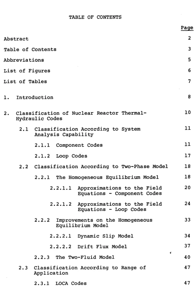
TABLE OF CONTENTS Page Abstract 2 Table of Contents 3 Abbreviations 5 List of Figures 6 List of Tables 7 1. Introduction 8
2. Classification of Nuclear Reactor Thermal- 10 Hydraulic Codes
2.1 Classification According to System 11 Analysis Capability
2.1.1 Component Codes 11
2.1.2 Loop Codes 17
2.2 Classification According to Two-Phase Model 18 2.2.1 The Homogeneous Equilibrium Model 18 2.2.1.1 Approximations to the Field 20
Equations - Component Codes
2.2.1.2 Approximations to the Field 24 Equations - Loop Codes
2.2.2 Improvements on the Homogeneous 33 Equilibrium Model
2.2.2.1 Dynamic Slip Model 34
2.2.2.2 Drift Flux Model 37
2.2.3 The Two-Fluid Model 40
2.3 Classification According to Range of 47 Application
2.3.1.1 2.3.1.2
Evaluation Model Codes ... Best Estimate Codes ...
48 49
3. Two-Phase Heat Transfer Models ... 3.1 Heat Transfer Regimes and Correlations
... 55 ... 57 4. Fuel 4.1 4.2 4.3 Rod Models ... Fuel Region ... Fuel-Clad Gap ... Clad Region ... 5. Numerical Methods . 6. Summary and Conclusions 6.1 Summary ... 6.2 Conclusions 6.2.1 Component Co 6.2.2 Loop Codes . ... 85 ... 85 ... 100 des ... 100 ,el e e e e . e e e e l e l . 1 0 5 .. 107 References Appendix 1 Appendix 2 Appendix 2 - References ... 112 117 127 REPORTS IN REACTOR THERMAL HYDRAULICS RELATED TO THE MIT ENERGY LABORATORY ELECTRIC POWER PROGRAM ...129
66 70 74 76
Abbreviations
The following abbreviations are referenced in this report:
ATWS: Anticipated Transients Without Scram COBRA: Coolant Boiling in Rod Arrays
DBA: Drift Flux Model DSM: Dynamic Slip Model
EPRI: Electric Power Research Institute
FLECHT: Full Length Emergency Cooling Heat Transfer HEM: Homogeneous Equilibrium Model
LOFT: Loss of Flow Transient LOCA: Loss of Coolent Accident MWR: Method of Weighted Residuals NSSS: Nuclear Steam Supply System RIAs: Reactivity Insertion Accidents RETRAN: RELAP4 - TRANsient
TRAC: Transient Reactor Analysis Code UHl: Upper Heat Injection
LIST OF FIGURES
No. Page
1 Coolant Centered and Rod Centered 13
2 Lateral Heat Conduction 16
3 Control Volumes for Subchannel Analysis 21 4 Geometry for Mass, Momentum and Energy Equations 26
5 Flow Path Control Volume 28
6 Lumped Parameter Simplification of Multi- 28 dimensional Flow Regimes
7 A Downcomer Representation in RELAP4 31 8 Schematic of RELAP4 Model of a Large PWR 32
9 PWR LOCA Analysis 50
10 BWR LOCA Analysis 51
11 Heat Transfer Regimes Traversed in Blowdown 54 12 Flow and Heat Transfer Regimes in Rod Array 55
with Vertical Flow
13 Heat Transfer Regimes at Fixed Pressure 56 14 Effect of Quality on Calculated Boiling Curve 61
LIST OF TABLES
No. Page
1.1 List of Reviewed Thermal-Hydraulic Codes 9 2.1 Cases Where 1-D HEM is not Acceptable 40 2.2 Two-Phase and Single-Phase Comparison with 42
Respect to the Flow Equations
2.3 Two-Phase Flow Model Description 45
2.4 ATWS in BWRs and PWRs 53
3.1 Heat Transfer Regime Selection Logic 67 3.2 Heat Transfer Correlations - Pre-CHF 68 3.3 Heat Transfer Correlations - Post-CHF 69 4.1 Approximations Made to the Equation of Heat 75
Conduction
6.1 Component and Loop Codes Comparisons 86 6.2 Models and Methods Used in Some Thermal- 89
Hydraulic Codes
99 6.3
1. Introduction
Numerous computer codes have been written to calculate the thermal-hydraulic characteristics of the reactor core and the primary loop under steady-state and operational transient conditions as well as hypothetical accidents. New versions of some of these codes are still to come. The main purposes of the continuing effort in the development of such computer codes have been improved computational effectiveness and improved ability to predict the response of the core and the primary loop. Therefore, efforts have been continued to incorporate
the recent models and methods of analysis in the areas of both hydrodynamics and heat transfer in two-phase flow to the extent that their prediction are reasonably reliable. For example, such a step by step development has been effected in the various versions of COBRA and RELAP Computer Programs.
The code users are therefore confronted with the need to develop criteria to choose the most appropriate version to handle a specified case. This is a two pronged decision since it requires not only an evaluation of the models and methods used in each code but also a comparison between the results and experimental data to observe how well these data are predicted.
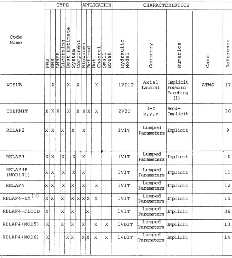
An attempt is made here to address the first step, i.e., comparison of the models and methods. To accomplish this, a study was made on the physical models and numerical methods which have been employed in the WOSUB, RETRAN, TRAC and THERMIT as well as various versions of COBRA and RELAP as listed in Table 1-1.
Table 1-1
List of reviewed thermal hydraulic codes.
Name of Code COBRA-I COBRA- I I COBRA-III COBRA-IIIC COBRA-IIIP COBRA-IV-I COBRA-DF COBRA-TF RELAP2 RELAP3 RELAP3B-MOD101 RELAP4 RELAP4-MOD5 RELAP4-MOD6 RELAP4-MOD7 RELAP 4-EM RELAP5 WOSUB RETRAN TRAC THERMIT Reference Number 1 2 3 4 5 6 7 8 9 10 11 12 13 14 14 15 16 17 18 19 20
These codes, especially COBRA and RELAP series, are well known thermal hydraulic computer codes and have been extensively used in the nuclear industry. WOSUB and RETRAN introduce a
new treatment for the hydrodynamics modeling. TRAC and THERMIT have gone further by applying the most advanced existing treat-ment of the phase flow, namely, three-dimensional,
two-fluid, non-equilibrium model.
In the comparison that follows, both the advantages and drawbacks are noted in each code and ultimately it is attempted
to assess the capability of each code for handling a specified case.
2. Classification of Nuclear Reactor Thermal-Hydraulic Codes The existing thermal hydraulic codes may be classified under several categories as follows:
1) Capability of the system analysis
This contains two different classes of codes, namely, system component codes and loop codes. Basically, the hot
channel or the fuel behavior codes are system component codes; however, some of these codes are extended to other situations far removed from subchannel (one channel) geometry. Integration of the down comer, jet pumps (in BWR's), bottom flooding, UHI and the like models into a component codes, makes itta vessel code. As distinct from the loop codes which are devised to analyze the whole primary side including reactor core and the secondary side, a variety of codes ranging from hot channel to vessel codes are called system component codes in this report.
2) Type of two-phase flow modeling
This part deals with the mathematical models used in thermal hydraulic codes to calculate the characteristics of the two-phase flow either in the reactor core or in the primary loop. The two pertinent methods in this respect, namely,
the homogeneous equilibrium model and the two-fluid model fall in this category.
3) Range of application
Since the capability of each code to handle flow and fuel rod calculations depends upon the mathematical models used to represent the physical situations as well as the
numerical methods employed, codes can be classified in these respects into steady-state, transient and accident analysis
(such as LOCA) codes. Naturally, the more demanding codes in this respect are ATWS and LOCA codes.
4) Type of application
Codes may also be classified based upon their types, i.e., Best Estimate (BE) type and Evaluation Model (EM) type. The latter group are basically devised for the purpose of licensing.
The type of nuclear reactor for which thermal hydraulic codes are devised (such as PWR, BWR and LMFBR) may be another category. A detailed discussion concerning each mentioned category is presented in the following sections.
2.1 Classification According to System Analysis Capability 2.1.1 Component Codes
of fluid passing axially along the parallel rod arrays. Such analysis is difficult to conduct due to the degree of freedom associated with parallel rod array and the two-phase flow and heat transfer involved in nuclear reactors. In addition, radial and axial variations of the fuel rod power generation exacerbates this situation.
Assumptions have been made to simplify the task of model-ing the hydrodynamics and heat transfer characteristics of the rod arrays.
Generally, there are three pertinent methods (2 1)used in rod bundle thermal hydraulic analysis of the nuclear reactor
core as well as heat exchangers, namely, (a)-subchannel analysis, (b)-porosity and distributed resistance approach and finally
(c)-benchmark rod-bundle analysis which uses a boundary fitted coordinate system.
The first approach is widely used in the subchannel codes such as COBRA, FLICA, HAMBO and THINC. Whereas the second approach is employed in THERMIT.
The subchannel approach will be more elaborated upon here, while a discussion in detail of these three concepts is
pre-sented in Ref 21.
In the subchannel approach, the rod array is considered to be subdivided into a number of parallel interacting flow
subchannels between the rods. The fluid enthalpy and mass velocity is then found by solving the field or conservation equations
for the control volume taken around the subchannel.
I I I I - - - -.- \ G 1 7 1 8 I 9 I 10
-O
0-00
6 1 7 ! 8 1 9 1 10'C> IC> fY61
I I I I :/ (a) 1 ;12 I 3 14 }15,-
-
r
-I-
-
-Ir_ _ . -. J -t-('):0,0
'r -,IIU',1
'iQ9V
I I _-)
IQI
I) 0.'1
iz
- ,
(b)Fig. 1 [22] (a) Coolant centered subchannel and conventional subchannel numbering. (b) Rod center system with subchannel
boundaries. - axis of I sy'rmetry
1~
I
wS _ _ ---\\I-
L-_ _
defined by lines of "zero-shear stress" between rods (Fig. l-b) seems to be a well-defined control volumes, it has become
customary to consider a coolant centered subchannel as a con-trol volume (Fig. -a). The number of the above-mentioned
control volumes axially is as many as the number of the channel length intervals.
Unlike the benchmark rod-bundles approach, the subchannel approach does not take into account the fine structure of both
**
velocity and temperature within a subchannel. In other words, there are no radial gradients of flow and enthalpy in the subchannels but only across subchannel boundaries. There-fore, the flow parameters such as velocity, void fraction,
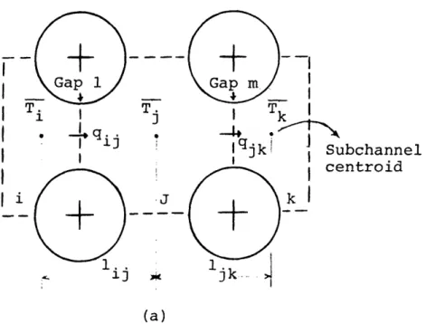
and temperature are averaged over the subchannel area. Further-more, the averaged values are assumed to be located at the sub-channel centroid. The following example elaborates the latter assumption. (48)
The transverse heat conduction in the fluid passing through the subchannels shown in Fig. 2-a becomes
T. - T.
q"ij= k. 1 [1.a3
13
* This model was first introduced in the Italian subchannel, code (CISE (23). It is especially preferred in modeling the strict annual two-phase flow condition, due to its resemblance to the annual geometry.
** An excellent discussion concerning the fine structure of the flow field within the coolant region is presented in Ref. (24).
and
T. - T
q jk= kjk J 1jj Il.b]
ljk
where q", k, T and 1 are heat flux, thermal conductivity,
averaged temperature and finally centroid-to-centroid distance between the adjacent subchannels respectively. Assuming
identical fuel rods, the centroid located averaged subchannel temperature seems to be a valid assumption for subchannel j. However, for subchannels i and k, it is expected that the averaged temperatures are located closer to the gap 1 and
gap m respectively. This is also the case for the temperatures shown in Fig. 2-b. The centroid located averaged temperature is a valid assumption for low conductivity coolants and high P ratios, whereas, it is a dramatic assumption for high
D *
conductivity coolants and tight rod bundles.
* A discussion in detail and a suggested method to correct the centroid located averaged values are presented in reference 25.
I Gap 1 I i I TI -I
I
I * I , I ij ibchannel =ntroid Ili_
i
. . 13 ljk-.,
(a)(
-a I -(b)Fig. 2 Lateral heat condition.
iJ
2.1.2 Loop Codes
Analysis of the whole primary system during transient conditions and hypothetical accidents such as loss of coolant, pump failure and nuclear excursions, necessitates modeling the whole loop components such as pipes, pressurizer (in PWR's),
pumps, steam generator, jet pumps (in BWR's), valves and reactor vessel. Also, the effects of the secondary system need to be considered.
The thermal hydraulic behavior of the reactor core during the course of a transient is tied to the core nuclear character-istics through the reactor kinetics. HIence, the reactivity
feedback should be considered in the process of the primary loop modeling.
The RELAP series of computer programs are the well-known transient loop codes which have been extensively used in the nuclear industry. These codes are basically devised to analyze transients and hypothetical accidents in the nuclear reactor loop of LWR's and mainly consist of four major parts as follows:
(1) a thermal hydraulic loop part, (2) a thermal hydraulic core part, (3) a heat conduction part,
(4) a nuclear part.
In these codes, the primary system is divided into volumes and junctions. The fluid volumes serve as control volumes, describe plenums, reactor core, pressurizer, pumps and heat exchangers. Each connection between volumes may be specified as a normal junction, a leak or a fill junction. A fill
junc-tion as its name implies, injects water into a well-specified volume. By definition, volumes specify a region of fluid within
a given set of fixed boundaries, whereas junctions are the common flow areas of connected volumes.(10) Any fluid volumes may be associated with a heat source or a heat sink, such as
fuel rods or the secondary side of a heat exchanger, respectively. While RELAP2 is able to handle only three control volumes with a fixed set of pipes connecting these volumes, representing the whole primary loop, RELAP3B and RELAP4 are capable of handling as many as 75 volumes and 100 junctions or even more, at the
expense of more computer core.
2.2 Classification According to Two-Phase Model 2.2.1 Homogeneous Equilibrium Model
Flow characteristics in component and loop codes are cal-culated through solving the field or conservation equations written for the well specified control volumes. The basic assumption made in modeling the two-phase flow is representing the two-phase by a pseudo single phase. This method of model-ing is also known as homogeneous equilibrium model (HEM). The HEM is extensively used in the thermal hydraulic codes. The homogeneous assumption implies that the phase velocities are equal and flow in the same direction, also the phase distribu-tion is uniform throughout the control volumes. The equilibrium assumption requires the phase to be at the same pressure and temperature.
The one dimensional HEM codes use an approximate set of
.*To do this, only the array sizes in the COMMON blocks should be increased.
field or conservation equations for the mixture in conjunc-tion with the constitutive relaconjunc-tions. The differential form of the conservation equations written for a mixture is as
(26) follows:
Local mixture continuity equation:
Pm + * m (P V ) = 0 [1]
3t
Local mixture momentum equations:
+ v +vm = Om [2]
7t PmVm [ m m] (Vm m
where the product V V gives an array of nine components. This product can be written as
VmVm = (Vi)m (Vk)m (i,k = 1,2,3,)
The surface stress tensor, T , is made up of the pressure and the normal and the shear stresses
T=P I
-m m
where T is the viscous stress tensor and T is a unit tensor. m
Local mixture energy equation:
mt (U + 1/2 V V ) + [VPm (U + 1/2 V )V ] = [3]
-[V (q - [T-V])] + pg-V +
m m m
where qm is heat flux, Qm is the body heating term and Um is the internal energy.
These balance equations need to be accompanied by the constitutive equations for Tm' qm, and Qm' the equation of
2.2.1.1 Approximation to the field equations -Component Codes
Approximations which are made in solving the conserva-tion equaconserva-tions in the component codes using the homogenous equilibrium model for the two-phase flow will be discussed in this section.
Basically, none of the existing subchannel codes use such a generalized three dimensional set of field equations as are given by Equations 1, 2 and 3. Rather simplifying assumptions are made in these equations. For example, in most of the COBRA versions, flow is assumed to have a
predominantly axial direction and all the "lateral" flow is lumped into one lateral momentum equation. The reason for such treatment may be justified by considering the
none-orthogonal characteristics of subchannel arrangement (Fig. 3) which do not allow treatment of the lateral or transverse momentum equations as rigorously as the axial momentum
equation. It is assumed that the interaction between two adjacent subchannels in the transverse direction is through two distinct processes,* namely, diversion cross-flow and turbulent mixing. Axial turbulent mixing between nodes is ignored.
The first process, diversion cross-flow is assumed to exist due to local transverse pressure difference in the
adjacent subchannels. Such a process transfers mass, momentum
*A more general classification is given in Ref. (27) and is referenced in the model making process of WOSUB (17). Also see Ref. (47) for basic notation in subchannel analysis.
Exact control volume for transverse mom. equi
Control volume for axial mom., equation
/
Fig. 3[21] Control volume: subchannel ana
and energy with the assumption that the cross flow loses its sense of direction when it enters a subchannel(4) Unlike the HEM versions of COBRA, WOSUB which is essentially devised for analysis of ATWS in BWRs does not account for diversion
cross flow.
The second process, turbulent mixing is assumed to be caused by both pressure and flow fluctuation. In this process, no net mass transfers, only energy and momentum are involved. This is due to the assumption of the equi-mass model.* The magnitude of the turbulent mixing term is determined either by some correlations or by a physical model that includes empirical constant.
All the COBRA versions account for a single phase
turbulent mixing while the two phase turbulent mixing term was added in the versions following COBRA-II, since COBRA-I does not account for this term.
It should be mentioned that forced flow mixing which is caused by some rod spacing methods such as a wire wrap or diverter vanes is taken into account, especially in those codes which are capable of analyzing fluid flow in LMFBRs such as COBRA-IIIC and COBRA-IV-I. Recently, a wire wrap model has been added(2 8 ) to COBRA-III-P which makes it capable of handling LMFBR flow analysis.
*The equi-volume model which is based on the change of same volume of flow is used in the MIXER code. For further detail
The steady-state versions of COBRA, namely, COBRA-I, COBRA-II and COBRA-III do not have any model for forced diversion cross flow.
A more complete form of transverse momentum equation is employed in COBRA-IIIC, COBRA-IIIP and COBRA-IV-I which includes the time and space acceleration of the diversion cross flow.
As a correction to the homogenous flow assumption, a one dimensional slip flow model which accounts for nonequal
phase velocities, is considered in all the COBRA series up to and including COBRA-IV-I. A subcooled void calculation is also added to these codes. However, COBRA-I and the explicit scheme of COBRA-IV-I (to be described) do not have a subcooled void option.
In the COBRA codes, the energy equation has been further simplified by assuming the turbulent mixing and convection heat transfer as the unique mechanisms for internal energy exchange. In such treatment, it is assumed that(2 9 )
-- no heat is generated within the fluid, -- changes in kinetic energy is small, -- no work against the gravity field.
Neglecting the time change of local pressure, , limits these codes to transients with times that are longer than the sonic propagation time through the channel. (4)
Unlike the previous versions, the COBRA-IV-I momentum equations account for the momentum flux term.
Further simplifications to the axial momentum equation have been made by neglecting surface tension contribution. This requires equal phase pressures. This basic assumption in addition to the assumed equal phase temperatures are the result of the thermodynamic equilibrium assumption.
2.2.1.2 Approximations to the field equations --Loop Codes
Assumptions made to solve the field equations in the loop codes using HEM are discussed here. Except for RELAP5, which is the latest publicly available version of RELAP series, the remaining versions use the HEM for their hydrodynamic
modeling. Therefore, a set of conservation equations written for a mixture (Equations 1, 2, & 3) is applicable for theoreti-cal considerations. For the practitheoreti-cal purposes, approximations have been made to this generalized set. The RELAP codes,
generally have a lumped parameter structure in which the
spatial effects are integrated over the control volume for the conservations of mass and energy. For example, the mass
balance in its differential form is
p = V-(p) [4]
at
Integrating over the control volume
-i
v
at
dr
=fjf
V- (pV)d-r [5]Now applying the divergence theorem to the right hand side of Equation [5], we get:
JJ
-T
ftV.(PV')dT= fT
pV nds V V v v or n-.(pV)ds + t d = 0 [6] s VUsing M as the existing mass in the volume J at J
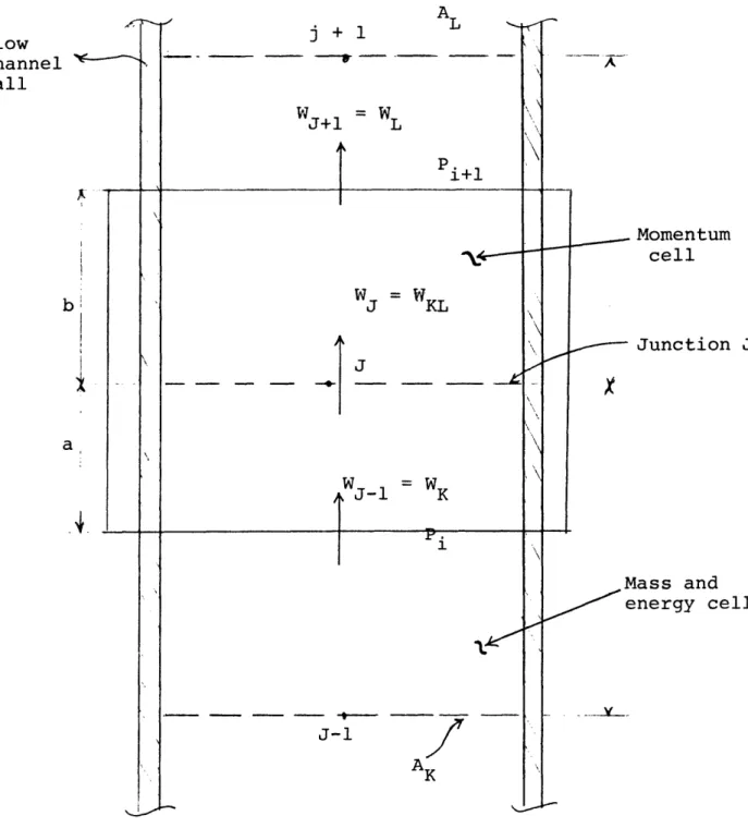
time ti and considering the term -ni .(pSV)i = W. which is equal to the inflow from side "i" into volume J (Fig. 4), the mass balance reduces to
[7]
dt M = E W..
dt 3 i=l 13
Similarly, a simplified form of the energy equation which has been used in RELAP2 and various MOD's of RELAP3 is
as follows:
n
dt= Wij. .h. .+Q [8
i=l ij1 1 j
where U. is the internal energy of volume J, hij is the enthalpy of fluid flowing from side i into volume j and finally Qj is the heat input to volume j.
The effect of kinetic, potential and frictional energies are neglected in Equation [8]. However, the RELAP4 energy equation accounts for kinetic and potential energy changes.
Unlike the mass and energy equations, the momentum equa-tion is written for a shifted control volume as shown in Fig. 4. This method minimizes the extrapolation of boundary conditions. The final form of the momentum equation used in various MOD's of RELAP3 is as follows:
j + 1 A WJ+1 = WL pi+l J -l-J-1 AK A X Momentum cell Junction J lass and energy cell
Fig. 4 Geometry for mass, momentum and energy quations.
Flow channel wall a W = WKL
----
~IJ
CJ-1 W1 L dW.
c(L d = P P + AP + Pdz kjWj j I
144gc dt i+lj 1 4 4 [9]
Pj
However, like the energy equation, an improved form of the momentum equation is implemented in RELAP4 which takes the
form: (30) dW. I It = (P +P ) (P+P ) - F F < -1-> z <-3- <-4--> <-5.-> < K L f> 6-L . L. L. L.
I
dP -I1
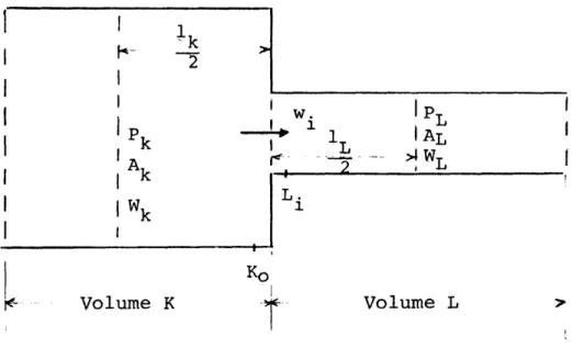
d(vW) - dF - KK A [10] soK o K 1 < 7--8- > <8 <--9 > -- > dWtIt is assumed that the junction inertia term, I dt in equa-tion [10] or the corresponding term d in equation [9] represents the rate of change of momentum everywhere in the selected control volume J. (Fig. 5) In equation 10, I is the geometric "inertia" for the flow path and also,
W. = flow rate in junction J, Pk = Pressure in volume K,
Pkgj = gravity head contribution for volume K, F = friction terms,
v = velocity, A = flow area.
The significance of each term in equation [10] is as follows: Term 1 represents the rate of change of momentum,
Term 2 and 4 represent the pressure drop between two volumes, Terms 3 and 5 represent gravity,
Terms 7 and 8 represent the friction and pressure drop associated with expansion and contraction.
I
w. IP 1 AL Lr.
. WL L. 1 Ko Volume K Volume LFig. 5 Flow path control volume.
K
-L
t
. J '
Fig. 626] Lumped parameter simplification of multidimensional flow- regimes.
-I I Pk IA I k I Wk I 1k -7 ! ! !-I
I
i
Mt
Term 9 represents the momentum flux or spatial acceleration term. Comparing Equations 9, used in RELAP3, and 10, used in RELAP4, it is obvious that the major difference is inclusion of the momentum flux term in Equation 10. The momentum flux term for a homogeneous volume becomes
L VLWL-WkVk
d(VW) = _ _
k A A
Although the inclusion of the momentum flux term has improved the momentum equation, there are some cases in the loop modeling that the code user has to ignore this term. (For example, when the given control volume, J, connects into more than two control volumes, as illustrated in Fig. 6; where the
double-ended arrows indicate junction). A similar case might be encountered in the lower plenum modeling when the flow is
highly three dimensional. In such cases, it is quite difficult to define the control volume boundaries for the momentum balance at each junction These examples clarify the inability of a
lumped parameter approach to model multidimensional regions. This is also the case in calculating the friction factor and heat transfer coefficient which by definition are(4 8)
du )dz
f = dr w) [11]
and
q =-k dT w =h(Tw-Tb) [12]
dr w
where and u are the viscosity and velocity of the flow and subscripts w and b represent values evaluated at wall and bulk
respectively,
It is clear from equations 11 and 12 that the deriva-tives are evaluated at the channel wall. However, since a lumped parameter approach doesn't account for velocity and
temperature profile, therefore, the above mentioned derivatives do not make sense. It is this reason which necessitates an input specified friction fractor for the codes using this approach.
The junction inertia term is another term in the
momentum equation (Equations 9 and 10) which becomes rather ambiguous in modeling the complex geometries. The junction inertia arises from an approximation in the momentum equation to the temporal inertia term as follows:(30)
x2 1 dw _ dx 2 dx dw
___
dx
dx
1I
[13]J
AX x)T A(x) dt l dw ( I dtwhere x = center of control volume 1 and x2 = center of control volume 2, and I is the geometric inertia for the flow path defined as:
I -(2 dx [14]
1
The geometric inertia for a homogeneous volume, Fig. 4,
a b
becomes I = 2A + 2A , however for complex geome,trics,
K L
the inertia term may be determined by using a simplified
(30)
respect is that the inertia of a junction is composed of two independent contributions, one from each connecting
volume. For example, Fig. 7 could represent a downcomer region. If we assume that Junction 1 communicates primarily with Junction 3, then with respect to the mentioned basic
assumption, the geometric inertia will be:
Ij = Ijl + Ij2 + Ij3 [15] or
L1 L2 L1
I j =2A- + 2 + 1
1 A2
3
Where L1 is the effective length of both Junctions 1 and 3 and the effective length of junction 2 is assumed to be 2L2.
f' '-
0
L1 I , - - : II
I L2I
1A
I
= Junction numberO
--- = Flow PathFig. 7(30) - A Downcomer Representation in RELAP4
A schematic of RELAP4 model of a PWR is presented in Fig. 8. It illustrates the complexity of accounting for all volumes and junctions in a LWR plant.
Steam rs sexis Stwnim gensra second side
Fig. 8[30] Schematic of RELAP4 model of a large PWR.
Stearn
0leam
menerator
.condary de
2.2.2 Improvements on the Homogeneous Equilibrium Model By retaining more field equations, a more realistic
approach to analysis of severe transients has become possible in reenct codes. The increased number of field equations enable a code to analyse transients in which the situation is far
beyond the capability of the rigid assumption of equal phase velocities and temperatures. In this respect, countercurrent two-phase flow and vapor-liquid phase separation during
small break transients and emergency core coolant delivery are notable examples.
Since in a non-homogenous flow slip exists between the two phases, there is a relative motion of one phase with respect to the other. This relative motion arises due to density and/or viscosity differences between phases where usually the less dense phase will flow at a higher local velocity than the more dense phase, except for the
gravity dominated flow(1 8 ) The general effect of slip is to lower the void fraction below the homogeneous value.
V
The slip or hold up ratio, s = g should not be VL
confused with the slip velocity VsL = VL - Vg, or drift velocity, a concept which is used in the drift flux model.
Unlike the one-dimensional HEM, a non-homogeneous, one dimensional flow calculation for a two-phase flow in thermodynamic equilibrium, involves the solution of one
equation of state and five differential equations: a
mixture energy equation and one continuity and one momentum equations for each phase as it is done in RELAP5.
2.2.2.1 Dynamic Slip Model
Simplified assumptions have been made to reduce the number of conservation equations while retaining the
improvements over HEM codes. This is done in WOSUB and COBRA-DF by using the concept of diffusion or drift flux model, and in RETRAN by introducing the dynamic slip model.
RETRAN computer code is basically developed from the RELAP series of codes. It is a one-dimensional code which solves four field equations written for a fluid volume
as follows: Mixture continuity, Momentum, Energy equation, and time dependent behaviour of the velocity difference, obtained by subtracting the momentum equations written
for each phase. This additional momentum equation reads:
SD (1 1 1 P 1
g DX DX P9 g X a Pk cc9P
AgL BgL sL ° [16]
where V,p,a,P represent velocity, density, void fraction and pressure respectively. Also AgL represents the surface area between vapor and liquid phase per unit volume and BgL
phases.
In deriving equation (16), the following assumptions have been made:
1) The wall friction is nearly equal for the two-phase.
2) The momentum exchange between phases due to mass exchange is small.
In addition to inclusion equation (16) in RETRAN, some improvements have been made in the field equations used in RELAP4, as follows:
1) Additional term in the mixture momentum
equation with respect to the momentum flux. Mixture momentum flux:
ax [A (agPg (V2)g) + al (V2 ) 1] =
a
+a VsL l 9Plg AAdditional Term
2) Additional term in energy equation which accounts for the time rate of change of kinetic energy,
at [ U2 [pA(-)].
3) Using a flow regime dependent two-phase flow friction multiplier.
2.2.2.2 Drift Flux Model
Unlike RETRAN, COBRA-DF which is a vessel code and uses the drift flux model, employs five field equations to determine phase enthalpy, density and velocity*. This code is used
exclusively for examination of upper heat injection of water during a LOCA in a PWR.
Vapor diffusion or drift flux model is another step toward modeling a non-homogeneous non-equilibrium flow. The basic concept in this model is to consider the mixture of the two-phase as a whole, rather than treating each phase separately. The DFM is more appropriate for the mixture where dynamics
of two components are closely coupled, however, it is still adequate where the relatively large axial dimension of the
systems gives sufficient interaction time (26)
In this model in addition to the three field equations written for the mixture, there is a diffusion
* THOR which is developed at BNL (31) uses the DFM and accounts for thermal non-equilibrium of the dispersed phase only.
equation written for the dispersed phase which reads:
ap O -t -+
[17]
gt + V(agpg Vm) = r - V (gpg Vgj) [17
where r is the phase change mass generation, Vgj and Vm are
g gm
the drift velocity and mixture velocity respectively.
WOSUB which is a BWR rod bundle computer code uses the DFM and solves four field equations written for a subchannel control volume, as follows:
1) continuity equation for mixture
2) continuity equation for vapor. This equation reads:
at (Pg9ai)i+A (P gJg) i = Ap gii + Pgi qgi [18]
where J = vapor flux g
qgi = vapor volume flow to subchannel i
T. = vapor volume generation in subchannel i per unit volume
Equation 18] indicates the fact that the temporal and spatial increase in the mass of vapor in subchannel i is due to vapor generation in the subchannel and vapor addition from the adjacent subchannels. The vapor volume generation term, , appears in Equation
[16] due to using the DFM. This term is part of the code constitutive package. It is modeled in
Y to the heat flux:
i-TAp h q [19]
v fg
where T is a coefficient depending upon coolant
condition, Ph is the heated perimeter and q" is heat flux in the fully developed nucleate boiling region, and A is the flow area. 'The effect of
subcooled boiling non-equilibrium condition is considered in the final form of .
3) Mixture axial momentum equation: This is the only momentum equation considered in the code. Therefore it is clear that WOSUB is strictly one dimensional. This may be justified by considering the fact that the intention of creating WOSUB, has been analysing the flow characteristics in encapsuled PWR bundles as well as BWR bundle geometry 1 7) in which, based on a channelwise node, the flow is predominately one dimensional. Nevertheless, the transverse effects are not totally forgotten. In fact a natural turbulence exchange mechanism is considered. Furthermore, vapor diffusion accounts for the tendency of diffusion vapor in the higher velocity regions.
These effects are considered in the momentum equation which is given by(1 7 ):
ap
~ 9LP (-I)P) + P +P aGz
az az )e+ az)ac + t)fr at
[h ( az d )t [20]
The last two terms stand for the axial momentum transferred into subchannel i and the turbulent shear stress, respectively. It is also evident that these two terms which connect the subchannel to its neighboring subchannels stem only from flow and pressure fluctuation and not transverse pressure difference as was discussed in Section
2.2.1.1.
4) Mixture energy equation which contains the inflow of enthalpy from adjacent subchannels.
Generally, the dynamic slip model, as it is used in RETRAN, has advantages over both slip ratio correlations, as used in most versions of COBRA, and DFMI, as used in WOSUB, as follows (1 8 )
1) The slip correlations are based on
steady-state data whereas the application is for transients. 2) They highly rely on empiricism which may
3) The slip velocity VsL = V - VL can only
assume positive values, hence the possibility of rising liquid and falling vapor cannot be predicted.
2.2.3 The Two-Fluid Model
The inability of the simplified methods to treat the multidimensional, non-equilibrium separated and dispersed
flows necessitates a better modeling of the two-phase flow. Anticipated reactor transients and postulated accidents like LOCA specially require a more realistic
treatment.
Those cases in which a one-dimensional HEM is not acceptable are tabulated in Table 2-1.
TABLE 2-1(32)
CASES WHERE 1-D HEM IS NOT ACCEPTABLE
Multidimensional Effects
Downcomer region Break flow entrance Plena Steam separators Steam generators Reactor core Non-Equilibrium Effects ECC injection Subcooled boiling Post-CHF transfer ECC heat transfer Low-quality blowdown Reflood quench front
Phase
Separation Small breaks Steam generator
Horizontal pipe flow Counter current flow PWR ECC bypass
The most flexible approach in modeling these cases
is through using a two-fluid, full non-equilibrium concept, which is the most sophisticated model employed so far in
treating the two-phase flow.
The derivation of the field equations in their general tensor form is quite involved. A detailed derivation is presented in Ref. 33. A short-hand representation for the
two-fluid model is 2V2T or UVUT which stands for unequal phase velocities and temperatures - whereas lVlT or EVET is used for HEM.
The unknowns and equations in this model are summarized in Table 2-2.
Table 2-2
Two Phase and Single Phase Comparison with Respect to the Flow
Equations
Case Unknowns # of Unkn. Type of Euations # of Egu.
Single V 3 Conservation of Mass 1
Phase P 1 " of Momentum 3
Flow T 1 " of Energy 1
p 1 Equation of State 1
6 6
a(void fra.) 1 Liquid Balance Equ. 1
V 3 Vapor " "
g
Two* V1 3 Liquid Mom. " 3
Phase P1 1 Vapor " " 3
Flow Pg 1 Liquid Energy 1
P 1 Vapor " " 1
T1 1 Equation of State 2
T 1 in Each Phase
g
12 12
* Table 2-3 gives a more detailed description of various approaches to modeling the two phase flow.
The two-fluid concept is employed in the advanced thermal hydraulic codes such as COBRA-TF, from BNWL, TRAC, KACHINA*, SOLA-FLX, SOLA-DF from LASL and finally THERMIT, which is developed at MIT under EPRI sponsorship.
TRAC is the state-of-the art primary loop analysis code. It employs a three-dimensional 2V2T model for the vessel and a one-dimensional drift flux model for the rest of the primary loop. The reactivity feedback is accounted for through coupling the point kinetic equations to the thermal hydraulic model.
The same concept of volume and junction defined for RELAP series is used in TRAC as well. A cylindrical coordinate system is used in TRAC for modeling the three-dimensional reactor vessel. This doesn't satisfy the purpose of a common reactor core analysis with its square array pattern governed by the bundle design. THERMIT which is a vessel code, is basically the cartesian version of TRAC. Hence, the same
field and constitutive equations used in TRAC is employed in THERMIT as well. A core or a fuel pin analysis in THERMIT essentially is based on treating a whole bundle cross-section
as one node where the local details have been smeared throughout the cross-section. Therefore, neither TRAC nor THERMIT account for a turbulent mixing process. Devising a subchannelwise
version for THERMIT using a coolant centered control volume
* K-FIX and K-TIF are two versions of KACHINA developed at LASL. The first stands for fully Implicit Exchange numerics and the second for Two Incompressible Fields.
has been initiated at MIT. This version will include a turbulent mixing model.
A summary of the aforementioned two-phase flow models is present in Table II-3. The notations and a description for specifications used in this Table are as follows:
a) A partial non-equilibrium model, Tk Tsat, assumes one phase is at saturation, temperature of the other (k) phase computed.
b) The notations T,q,r,M and E stand for viscous stress, conduction heat transfer, interphase
mass, momentum and energy exchange respectively.
c) The notations: Vr, VG - V, VG - J stand for relative velocity, diffusional velocity and the drift term respectively.
A glance at this table shows clearly that although the 2V2T model imposes no restriction on the flow condition such as velocity or enthalpy, however it contains the
largest number of constitutive equations and it seems that the empiricism which enters in these equations is introduced at a more basic level than the less complicated models such as 1V1T approach.
IH W It r-m CN ,_-m I Q) Hl Ero ro 0 U) a 0 0 Ql r-a) 0 w~
I (N -I rd E-or 0 .HQ -0' U) 0I o 1b d 0 o
2.3 Classification According to Range of Application 2.3.1 LOCA CODES
The major task of thermal-hydraulic LOCA codes is analysis of the severe cases that are encountered by the reactor core or the primary loop during the period of a loss of coolant accident. The four phases of a LOCA, for a PWR double ended cold leg break, in order of occurrence are as follows:
1)*- A blowdown phase which generally lasts for 30 seconds, with 2200 psia initial pressure, and ends when ECCS starts
to work.
2)- About sixty seconds after break initiation ECC fills the lower plenum and reaches the bottom of the core (Refill Phase). 3)- The refill phase is followed by a REFLOOD phase which lasts for about 150 seconds, during which the core is fully flooded and quenched by the coolant.
4)- Long-term cooling then follows.
It has become customary to call a code a LOCA code even if it is capable of describing only the first phase of the four aforementioned phases. At the same time two codes that are capable of handling the blowdown, may be entirely
different with respect to their type. For example, one can be a component code whereas the other a loop code. To avoid any
* This step is divided in two periods according to Ref. 31, namely: a) Adiabatic Liquid Depressurization, b) The Blowdown Period.
confusion, a classification is necessary with respect to the code's application and type, in addition to the
physical models and numerical methods. A usual way to classify the LOCA codes is by categorizing them into two groups as follows.
2.3.1.1 Evaluation Model Codes
The first group contains those codes which employ a conservative basis for their physical models. Such
conservatism is mandated to satisfy the NRC acceptance
criteria. These codes are called the EM-codes for Evaluation Model. They constitute the WREM package which has the capa-bility to analyse the postulated LOCA with ECC injection in
(35) accordance with current commission acceptance criteria The codes which constitute the WREM package (36) are the
existing computer programs which have been modified to comply with the USNRC criteria. Most of the RELAP series of computer codes are a LOCA Licensing code such as RELAP4-MOD5 and
RELAP5-MOD7. Whereas RELAP3B-MOD101 is essentially devised to analyse ATWS and RELAP4-MOD6 and RELAP5 are not based on conservative correlations. RELAP4-EM is the only version of RELAP which is specifically modified to comply with
acceptance criteria.
The present EM codes comprise an assembly of codes run sequentially. Each member of the sequence is a
stand-alone code developed for some special application. With this respect, RELAP4-EM in conjunction with RELAP4-FLOOD(3 6 )
and TOODEE2(3 7 ) constitute the WREM package which perform the PWR LOCA analysis. Also a combination of RELAP4-EM and MOXY-EM(3 8 ) constitute the WREM package for a BWR LOCA analysis. The respected procedure for the above mentioned analysis are presented in Fig. 8 and 9.
2.3.1.2 Best Estimate Codes
Most of the LOCA codes lay in this category. The basic physical models used in these codes ely on the best estimate assessment rather than conservative correlations. Unlike the EM-codes, the BE-codes are mostly devised as one large system code consisting of various functions previously performed via the separated stand-alone codes. This guarantees the proper compatibility and continuity between the various calculational phases. As an example, the multi-purpose loop code TRAC can be used for the analysis of the whole phases of a LOCA namely, blowdown, refill
and reflood. Unlike the EM-codes which mostly use a homo-geneous equilibrium model in conjunction with a lumped parameter approach for their analysis, the best-estimate codes are much more demanding and the most recent BE-codes employ the state-of-the-art physical models. Therefore they
U w Z 0 D UC~ E-4 0 E O D =r Ep Q z 0 ,< 4 I U] E4 U E- f .1 h r= E- U O U E- U 0 pOP P4 U) Ln cn r- H ., 0 E-H 4 Er D E4 U Q 0 0 w 1Y ¢0 0 I Ir II 5I F:14 w P4 O O 0 E-o 0 H I p: 1-4 H h N ., CNJ 0 CN C 12 z :R pq 0 ccn i-1 z 0 0 -:: PQ W E-1 U H H Z W H I6 jI 'N r J t ol -- |
0 z H HOQ O z 0 H O H eqV 14 PI Eq 0 U o H z z O r EHH 0 < ! P4U C: H U) A Z *Hq U H U 0 d
p
0o
ml ,t Ln o Z 0 H P4 0 U U _D W P 2 0 H E-4 H 0W >-5 P 3 P4 Cl) W H U] W5: W Z E-4 F: H UEH ~D ] ~H K a $4 z z ::i
I ican be used to evaluate the degree of conservatism employed in the licensing (EM) calculations.
No codes have specifically been devised to handle the ATWS type of transients. In Table II-4 the causes and consequences of ATWS transients in both PWR's and BWR's are shown.
3. Two-Phase Heat Transfer Model
The energy balance of the field equations contains the contribution of the so-called wall heat transfer which accounts for the amount of heat transferred into or
out of the control volume through a combination of convection and conduction heat transfer. This requires models for the wall heat transfer.
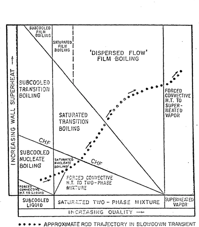
During hypothetical LOCA's, nearly all the two-phase heat transfer regimes are experienced by the coolant in the core of the NSSS, the steam generators, and the pipe
of the hydraulic loop (see Fig. 11). This interdependence of the hydrodynamics and the wall heat transfer, as shown in Fig. 12, is accounted for in the thermal hydraulic LOCA codes through using a two-phase heat transfer package.
These regimes are elaborated on in a pool boiling curve
drawn for a fixed pressure, and shown in Fig. 13. According to Fig. 13, the path ABCDEF is obtained in a temperature
ot -P O to k 0) 0) )4-0 O O a) -rq-Ha) f 0 c *H 0) U H UH k 4 U)m 4 04-Hr-H 4P rd a) >(D N -*H 0 --H 0 U0) ) 4 IN ,--I i ,-- a ·,E ,:1 " a) 4:3 ·- ):) *H . i, H r4 " 4 4 r : rd IN ·d ( d O -- ,H 4 U)-H -H O) r I .H) O . i 0 q r, . /L In l.. - .* . :O -I ,-I O O 0 I O . O ~ O-. k mu aoU) -) E$ r o OU (D O O O ·Oa O O,' ) OU ) 4 43 4 H I :> -to t 44 04J 43 t )0 ) ) *H 04 O ., nl - > 0::J > II ) O > IH-H-d - U 4J k k) a) 4 10-P- O ". O 4 O-k ¢ -H C 3 Z O Z UH O a O 0 r Q H U H # .. H , > k En t m 4. 4--H a) HH <. 3 sik P m4 k P3 * O O O k H) 0O 0 r 4 · U) 0) 0l) t7 0-01) U) 0 u > -i 4 U) 0 U 54 $ I H 04 M U) Q) QH *i 0) U H 54 4 rQ 0 P 04-H -O O O 'a O U En a) ro c Jm r. o ,- r4 CV U) O >) 0 > I 1) -1 (D (0 (00) a) E! 040) 5-4 *H ~ 5-1 C) 5-4 0 :: 0) a 4. 4.3 "O OH ( 0 ) 0 0) a) 0 0U 5-O U4 U r 4 r-i I i 44 0 .- ·0 -- 4 a) 5-4 ·H 0 4) --HO 4-3O) ,-4 I 0) ,-4 ol 3 q) -EC 0) to F. 04- Id 3 d H f (a 0) O 0 k c)-H k P4 H 4P 4 kU a) O r8 I 3-a 0-H I 0rI O',-I-P u O 0 O 0 -, Id ~U)0) I PO O- g UoH E a040H H, 04H 1'4 - -4 H 0 4J4J L R i- ,--Imd O , O O O CCfr U) U) (a 3U O O Pm"O E4 r u - (a (D I -I O - 0 EI 4 ( Q) -H 4k k Wl k 4 3.-) P4 5 UI k . O w 3u 0> n I t0 k 1 a D 04 44 P U) tr 2 k i c))* . ) - --I I > k > > mUU .,q 0 r *H -H 5.-ri d >i 4 .U) I ) 0 w .0)4it Id C 4u -H U (d a4w 4-Hk )O H4) O ) 0IW4-O Z 0404-U Ok Z U 0c4 ) 4- -H 0) E U4 5r - U) 4 rId k Id k 3 ) O aH - O Q)k u) ) UO a 0'~~~ _ 404rd 0) Od O 1 >1 -i,-.- 4 0 -H 0 ri En to w 0 m X En)-H0()a: ~-14-4 i-l (d 104 L 3 uz t 1f*1 u),B I 0) -H k 4 4 4J 4J -H 0I -H I I t .H to 4 0)00O k - -H -P 4. 0 ri :3 O 04 O 3 >0 : -iH H-04-I 4 U; to (0 En I CN
0)1
(l (d E-4 Itzr ,Ln 0 "-. . _ .- --- -- -C . _ --- . __SUBCOOLED
TRA
N5!
i O11
'
,
BO1LING
SUBCOOLED
NUCLEATE
BO Li NG
FORFC CONVECti LH.T. TO LlOUtD SUBCOOLED LIQUID'DISPERSED FLOW'
FILM
BOILING
S S '* -/0 oFORCED '~ · ~ CONVECTIVE oo H.T.ro
o SUPER-0\Io
SlEAlTESAT .
RATED
/
VAPOtTRAN
S!
T!
ON
BO LING
A · SAT! ED CLEATE 0 r.TS i.'O-,t? \'/~tx7~~C
__$ATU
S,
A .L. D7
,-'l
.O '-TRPt'
.fAS .- IIXTURE
SUPEH EA EVUPEOR' Iq ...i
r- CR.ASI,G QUALITTY-Fig. 11 Heat transfer regimes traversed in blowdown.
i i i i i '2; W. 04 Cl) CL-0 2 L)
cr
C,z
t3l
7-kn* * e a . APPROXIMATE ROD TRAJECTORY I,, SLO\'¥.DO'w'N TRANSIENT I
-II i _
- ___ -- _--_,__I __I
I( -,; I?.g ir-,.:, ;.. II ... . ... __. f ;i l I e -P. s E L. i qid Deficient ?ist, Sprcty or Disper s ed Annular or Film Slug ,Ch::rr, or Froth B3ubbl t Froth Sinjl..-P \',atr
L-C 'I, . I' ·- ., Ik23
cc).
.D0'
'. I I, P 9) P,, '0 . * I . ,I 9 IA
FI'. .Oiivetcti ll to upt:rhoJ 'icj St:.-rn ¢oivection end fRadiation to Soturoted LiquidCritical t4sut Flux
4( dryout) I Forced Convection Throulh li.lultd Flm .1 I [ Suhcooled l-Jiling (:nnve clion to .'ater Fig. 12 [19] to S teinI ond nvoct;on tio.n por Firn I uot Flux n oii.) n to Floa
Flow and heat transfer regimes in rod array with vertical upflow.
TreritJ f-r~ I':;I'L1 lle-jo Tron!.', !r r =· r ··: ·· -· ·--,r r· · -35i`. 2·r·. · 5` · · -.r. I-:i ·- · ,'r r·t ·· r. · f :·. ·: '." · · r -I I f I
I
Nuc!!;te 3ih I r ._ P 0 Ji- t-T VC O
a
j
I
t C C (SH Z,I./nljE) ,,b 'Xnl .V3H 33ViansI-,.
C', I-to,
n - (ACa 0 F. E .Ein asa) I-- w Q C e to, ar X X XIL Eo ._1 LL lfcontrolled surface as the temperature is increased. In general, the same path on cooldown process is not followed in the heat-up process by the boiling mechanics. For
example in a heat flux controlled surface, the path ABCC'F will be followed in which point c' indicates the new equilibrium state of the surface at the heat flux value qCHF
At steady-state operation conditions, a NSSS fuel rod is a heat flux-controlled surface with a non-uniform axial heat flux distribution. In this case a reduction of the heat flux may be traced on the curve of Fig. 13 by the path EC'D E'BA( 1 8 ).
Unlike the steady-state conditions, during a hypothe-tical LOCA it is not lear which mechanism prevails, since the fuel rods of NSSS's may behave as heat flux-controlled surfaces for some parts of the transient and as temperature controlled surfaces for other parts of the transient.
3.1 Heat Transfer Regimes and Correlations
The recent thermal hydraulic LOCA codes have increased their capability of the two-phase heat transfer assessment by inclusion of more distinct heat transfer regimes and using more realistic correlations for calculations of the heat transfer coefficient in each regime.
As was discussed in section 3.1, a stand-alone LOCA code is capable of handling only one phase of hypothetical LOCA's, whereas integrated LOCA codes such as RELAP4-MOD7 and TRAC have the capability of calculating both blowdown and refill/reflood phases of a LOCA. This capability is made possible through inclusion of the unique features of bottom flooding (in PWR) and top spray (in BWR) of reflood heat transfer, in the blowdown heat transfer package. Such features are quench front, rewetting and liquid entrainment. Also thermal radiation and dispersed flow film boiling are specially pronounced in reflood heat transfer and are treated explicitly in the reflood heat transfer packages*.
The heat transfer package which was used in the early versions of the RELAP series such as RELAP2, is used
extensively in the thermal hydraulic codes**. This package is used in various versions of RELAP3 as well as RELAP3B-MOD101. Later it was modified by replacing the quality by void fraction to determine the pre-CHF heat transfer
regimes and by treating the transition boiling explicitly in which case the heat transfer coefficient is calculated using the MC DOUNOUCH, MILICH and KING correlation. Also
* See REFLUX (3 9 ) package which is developed at MIT to analyse the reflood phase of a LOCA.
**This package is essentially adopted from the THETA hot-channel code.
the Berenson and Groeneveld correlations were added to the formerly existing Dougall-Rohsenow correlation in the film boiling regime. RELAP4-MOD5 and RETRAN use this modified version and a simplified form of this new
version was implemented in COBRA-IV-I. RELAP4-EM employs the new version with further modifications to satisfy the acceptance criteria. For example return to nucleate boiling is precluded once CHF happens. Also the GE
correlation is added to the CHF correlations as an
option to replace the Barnett correlation for BWR analysis. There are however several disadvantages associated with this package( 4 0 ).
1) There is no CHF scheme to consider CHF during flow reversal or stagnation, which are charactieristic of blowdown in large, cold leg breaks in PWR's.
2) Use of Thom's correlation up to a void fraction equal to 0.8 which corresponds to a quality equal to 0.42 at 2250 Psia, which is above the quality range for which this
correlation was verified.
3) Extensive use of correlations whose data base rely on tube or annular geometry, while their application is for rod bundle geometry.
4) Using the correlations which have a steady-state data base for transient conditions.
For this reason a heat transfer package called BEEST developed at MIT to overcome these drawbacks. BEEST(4 0 )
stands for BEst ESTimate heat transfer analysis. It is based on best estimate assessment rather than conservative correlations. Several tests of BEEST showed that it is able to construct the complete boiling curve where
different heat transfer regimes are smoothly connected (Fig. 14). The heat gransfer selection logic in this package is based on the comparison of the clad surface temperature with the two distinct temperatures on the boiling curve, namely the temperature at the minimum stable film boiling point, TMSFB, and the temperature at the critical heat flux point, TCHF (Fig. 13). This is
certainly an unambiguous, efficient and valid criterion for selecting the appropriate heat transfer regime. Once the regime is identified, the second step is to apply a chosen correlation for the heat transfer regime selected. The upflow and downflow heat transfer are treated separately through
using the void fraction. The transition boiling in this package is treated in a unique way. This treatment is based upon an interpolation between the Q"MSFB and Q" CHF (which are the heat flux corresponding to the TMSFB and TCHF) with
+4. 4 - I-LL CO de i1v iC)' IC0' 1
TwA
-~,,~. (°~)
40] Effect lty of on calculated qua boiling curve Fig. 14 [40] Effect of quality on calculated boiling curve
respect to the temperature ratio as follows*:
Q" TB = E Q"cF+ (l-E) QM CHF [21]
MSFB
where
E = (Twall TMSFB)/(TCHF TMSFB)
In equation (22), E may be interpreted as the fraction of wall area that is wet. BEEST uses the Biasi correlation for the CHF calculations. The Biasi correlation is
essentially a dry-out correlation. Therefore it is
appropriate for high flows and qualities where the vapor is a dominant factor leading to dry-out. For low flows and qualities the void-CHF correlation developed at MIT is used. The RELAP heat transfer package which was
discussed earlier uses the Barnett correlation as well as
* This concept was first introduced by W. Kirchner
(see Ref. 41), in the form of a Log-Log interpolation:
CHFTwall
TB ( T ) where
wall sat CHF
Log Q"C - Log QMSFB Log TCHF - Log TMSFB
Kirchner then applied his model in the heat transfer package of TRAC.
the modified Barnett and the B&W-2 correlations for the CHF calculations. In the pre-CHF regimes, the Chen correlation is used in the subcooled nucleate boiling, saturated nucleate boiling as well as forced convection vaporization. This correlation has predicted the
existing data with reasonable agreement( 3 8 ) as compared to the other correlations such as: Dengler-Addams, Schrock-Grossman, Bennett et al, Sani and finally
Guerrieri - Talty. The Chen correlation is applicable to flow regimes from slug flow through annular flow. While its data base is for low pressures ( 4 2 ), in most applications it is used at elevated pressures. Also, its dependence on the wall temperature which necessitates an alternative procedures, makes it less desirable.
The advantages of the BEEST heat transfer package namely, treating the upflow and downflow separately, using a once through heat transfer regime selection logic, using wall temperature as a heat transfer regime selection tool, using a best estimate assessment and incorporating the new improvements in heat transfer, has made it acceptable to the state-of-the-art LOCA codes. THERMIT uses BEEST with some modifications such as replacement of the void fraction calculated from DFM by that calculated in THERMIT. TRAC heat transfer packages is also very similar to BEEST. In fact it can be considered as an improved version of BEEST
with the following additions:
1) Adding two options to the CHF correlation namely, the Bowring and the Zuber Pool boiling correlations.
2) Inclusion of the thermal radiation contribution in the film boiling regime.
3) Using a horizontal film condensation to represent the low flow rates.
4) Inclusion of a vertical film condensation regime.
5) Considering laminar and turbulent flow correlations in steady-state calculation for forced convection to two-phase mixture.
A comparison of heat transfer selection logic and correlations used in different thermal-hydraulic codes is present in Tables 1.1, 1.2 and 1.3. The notations and
specifications used in these tables are as follows:
1) Thermodynamic quality is represented by h-hf
x =h where h represents enthalpy, whereas
fg W
X represents the true quality X = g where W Wf+W '
Wfw r
2) The notations , Tw, Tf, Tat P,G represent the void fraction, wall, fluid and saturated
temperatures, pressure and finally mass flux, respectively. The dimension of the pressure and mass flux are in terms of "Psia" and "lbm/hr-ft2
respectively.
3) The terms "High" and "Low" flow used in these tables are in accordance with the flooding correlation which read
1 1
.-1 2
J + mJg = K [23]
f g
where for turbulent flow m is equal to unity and Jf and Jg are dimensionless velocities:
1 1
* 2 2
f = Jf f [ gD(pf-P g)]
f =J f1 [24]
Jg = J pg [gD (pf-pg)]
where D is pipe diameter and K is the flow criteria. For example, in low flow region according to Ref. 40, this criterion is * 1 * 1 Jf 2 - Jg 2 <1.36 for upflow 1[25] Jf 2 + Jg 7 <3.5 for downflow f 2 + Jg
![Fig. 1 [22] (a) Coolant centered subchannel and conventional subchannel numbering.](https://thumb-eu.123doks.com/thumbv2/123doknet/14450911.518585/16.940.222.713.79.887/fig-coolant-centered-subchannel-conventional-subchannel-numbering.webp)
![Fig. 3[21] Control volume:](https://thumb-eu.123doks.com/thumbv2/123doknet/14450911.518585/24.933.155.867.90.1103/fig-control-volume.webp)

![Fig. 8[30] Schematic of RELAP4 model of a large PWR.](https://thumb-eu.123doks.com/thumbv2/123doknet/14450911.518585/35.915.130.863.236.781/fig-schematic-relap-model-large-pwr.webp)