Publisher’s version / Version de l'éditeur:
Vous avez des questions? Nous pouvons vous aider. Pour communiquer directement avec un auteur, consultez la première page de la revue dans laquelle son article a été publié afin de trouver ses coordonnées. Si vous n’arrivez pas à les repérer, communiquez avec nous à PublicationsArchive-ArchivesPublications@nrc-cnrc.gc.ca.
Questions? Contact the NRC Publications Archive team at
PublicationsArchive-ArchivesPublications@nrc-cnrc.gc.ca. If you wish to email the authors directly, please see the first page of the publication for their contact information.
https://publications-cnrc.canada.ca/fra/droits
L’accès à ce site Web et l’utilisation de son contenu sont assujettis aux conditions présentées dans le site
LISEZ CES CONDITIONS ATTENTIVEMENT AVANT D’UTILISER CE SITE WEB.
Proton Exchange Membrane Fuel Cells: Materials Properties and Performance,
pp. 343-426, 2009-05-01
READ THESE TERMS AND CONDITIONS CAREFULLY BEFORE USING THIS WEBSITE.
https://nrc-publications.canada.ca/eng/copyright
NRC Publications Archive Record / Notice des Archives des publications du CNRC : https://nrc-publications.canada.ca/eng/view/object/?id=ad5cdedb-ea40-464d-a145-bf63fc0cbd9a https://publications-cnrc.canada.ca/fra/voir/objet/?id=ad5cdedb-ea40-464d-a145-bf63fc0cbd9a
Access and use of this website and the material on it are subject to the Terms and Conditions set forth at
Physical modeling of materials for PEFCs: a balancing act of water and
complex morphologies
Physical Modeling of Materials for
PEFCs: A Balancing Act of Water
and Complex Morphologies
Michael H. Eikerling and Kourosh Malek
CONTENTS
6.1 Introduction ...345
6.1.1 Energy Conversion in Polymer Electrolyte Fuel Cells ...345
6.2 Challenges for Materials and Operation ...346
6.3 Physical Theory and Molecular Modeling of Materials ...348
6.3.1 The Membrane ...348
6.3.2 The Catalyst Layers ...349
6.4 Complex Morphology and the Role of Water ...350
6.4.1 The Role of Water ...350
6.4.2 The Hierarchy of Scales ... 352
6.5 Structural Organization and Dynamic Properties of Ionomer Membranes ...353
6.5.1 Status of and Directions in Membrane Research ...354
6.5.2 Structure and Dynamics in the Membrane ...356
6.5.3 Molecular Modeling of Self-Organization ...360
6.5.3.1 Atomistic Simulations ...360
6.5.3.2 Mesoscale Coarse-Grained Simulations ...363
6.6 Water Sorption in PEMs ... 369
6.6.1 Structure of Water in PEMs: Classiication Schemes ... 369
6.6.2 Phenomenology of Water Sorption ... 371
6.6.3 Thermodynamic Model of Water Sorption ... 372
6.7 Proton Transport from the Bottom Up ... 381
6.7.1 Proton Transport Phenomena in Membranes ... 381
6.7.2 Pore-Scale Models of Proton Conduction ...383
6.7.3 Proton Mobility near the Polymer–Water Interface ...385
6.7.4 Network Model of Membrane Conductivity ... 391
6.7.5 Electro-Osmotic Drag ... 394
6.9 Ionomer in Catalyst Layers: Structure Formation and
Performance ...404
6.9.1 Challenges for Design and Operation of Catalyst Layers ...404
6.9.2 Multiscale Modeling Scheme of Catalyst Layers ...407
6.9.3 Mesoscale Simulations of Self-Organization in Catalyst Layers ...409
6.9.4 Main Results of Macrohomogeneous Catalyst Layer Models ... 413
6.9.5 Water Management in Catalyst Layers ... 415
6.10 Concluding Remarks ...420
Symbols ... 424
Greek Symbols ...426
6.1 Introduction
6.1.1 Energy Conversion in Polymer Electrolyte Fuel Cells
The powerfulbiological machinery of energy conversion proceeds via redox reactions in aqueous media that involve electron and proton transfer between molecular entities.1,2 Nature devised concerted sequences of these processes that generate electrochemical potential gradients across cell membranes and thereby enable the storage and the release of electrical energy.
Polymer electrolyte fuel cells (PEFCs) represent the most versatile member of the family of fuel cells.3,4 Due to unrivaled thermodynamic eficiencies of direct conversion of chemical energy into electrical energy, high energy densities, and ideal compatibility with hydrogen as a fuel, PEFCs are widely considered a primary solution to the global energy challenge.4–7 They could replace internal combustion engines in vehicles and supply energy to a plethora of power-hungry portable and stationary applications. The success-ful introduction of PEFC hinges, however, on the development of advanced materials and the engineering of cells and stacks that optimize power den-sities and voltage eficiencies. Moreover, fuel cells compete with existing energy conversion technologies in terms of their range of viable operating conditions, stability, and overall system cost.
Under normal operation of an H2/O2 fuel cell, anodic oxidation of H2 (or other hydrocarbons or alcoholic fuels)—that is, H2→ 2H+ + 2e–—produces protons that move through the polymer electrolyte membrane (PEM) to the cathode, where reduction of O2 (i.e., ½ O2 + 2H+ + 2e– → H2O) produces water. The overall redox process is H2 + ½ O2 → H2O. The electronically insulating PEM forces electrons produced at the anode through an external electric cir-cuit to the cathode to perform work in stationary power units, drive trains of electric vehicles, cell phones, laptops, etc. The maximum obtainable work from the controlled progression of electron and proton transfer processes in PEFCs corresponds to the Gibbs free energy difference, ∆G, between prod-uct state (H2O) and reactant state of the redox couple (H2/O2). Direct alcohol fuel cells follow the same thermodynamic principles; the redox couples are (CH3OH/O2), (C2H5OH/O2), etc. and the product state involves H2O and CO2.
The thermodynamic eficiency of the cell is given by the ratio of ∆G over the reaction enthalpy ∆H,
εth= ∆ = − ∆ ∆ ∆ G H T S H 1 ,
where ∆S is the reaction entropy.
The portion ∆Q = ∆H – ∆G = T∆S of ∆H is transformed into heat. Ideal theo-retical eficiencies eth are determined by the types and amounts of reactants and by the operating temperature. Fuel cells have an eficiency advantage over
combustion engines because the latter are subdued to the Carnot limitation. High thermodynamic eficiencies are possible for typical fuel cell reactions (e.g., eth = 0.83 (at 25°C) for H2 + 1/2O2 → H2O(l)). The electrical potential differ-ence between anode and cathode, Eeq = –∆G/n
tF, which is also called the
elec-tromotive force or open-circuit voltage, drives electrons through the external metal wiring. Here, nt is the number of electrons transferred in the overall reaction (nt = 2 for the reactions in an H2/O2 fuel cell, as speciied previously).
6.2 Challenges for Materials and Operation
Chemical reactions and thermodynamic considerations of PEFCs are seem-ingly straightforward. The challenges for optimizing fuel cell operation are hidden, however, in the ine microscopic details of structures and processes in their materials. The multilayered design of a single PEFC, depicted in Figure 6.1, includes a proton-conducting PEM sandwiched between anode and cathode. Each electrode compartment comprises an active catalyst layer (CL), which accommodates inely dispersed nanoparticles of Pt on a carbo-naceous substrate; a gas diffusion layer (GDL); and a low ield (FF) plate that serves at the same time as a current collector (CC) and a bipolar plate between neighboring cells in a fuel cell stack.
Flow F ie ld Flow F ie ld C atalyst L ayer C atalyst L ayer G as T ransp or t L ayer G as T ransp or t L ayer Polymer Elect roly te Membran e Anode + O2, Air Water H2, Fuel Electrical Load Net Reaction: H2 + ½ O2 H2O H+ H2 2H+ + 2e– ½ O H2O 2 + 2H+ + 2e– e– e– – Cathode FIGURE 6.1
Schematic depiction of seven-layer structure and basic processes in polymer electrolyte fuel cells under standard operation with hydrogen and oxygen.
Fuel cell operation entails (1) coupled proton migration and water luxes in the PEM, (2) circulation and electrochemical conversion of electrons, pro-tons, reactant gases, and water in CLs, and (3) gaseous diffusion and water exchange via vaporization/condensation in pores and channels of CLs, GDLs, and FFs. All components of an operating cell have to cooperate well in order to optimize the highly nonlinear interplay of these processes. It can be estimated that this optimization involves several 10s of parameters.
In general, the fuel cell voltage E is a complex function of the working cur-rent density j0; that is, E = f(j0). This relationship is sensitive to material struc-tures, cell design, and operation conditions. Irreversible voltage losses due to mass transport by diffusion and convection of reactant gases and product water in diffusion media, migration of protons and electrons in conduction media, nonuniform distributions of reaction rates, and limited kinetics of thermally activated electrocatalytic processes at fuel cell electrodes reduce E relative to Eeq, thereby causing the diminished voltage eficiency e
V = E/
Eeq. The major objectives of worldwide research efforts in the development of advanced materials and the engineering of cells and stacks is to maximize fuel cell eficiency,
εfc=ε εth⋅ V= −eq
− +
nFE nFE T S∆ ,
and power density, P = j0E, at given cost and lifetime of the cell.
Concentrating on the operation of the so-called membrane electrode assembly (MEA), E includes irreversible voltage losses due to proton conduc-tion in the PEM and voltage losses due to transport and activaconduc-tion of elec-trocatalytic processes involved in the oxygen reduction reaction (ORR) in the cathode catalyst layer (CCL):
E j( )0 =Eeq−R ( )j j0 0− ( )j0 − ( ).j0
PEM ηCCL ηother (6.1)
In general, the membrane resistance RPEM should be considered as a func-tion of j0, as indicated in Equation (6.1). Nonuniform distribution of water in PEMs due to improper water balance can lead to nonlinear effects in RPEM(j0).8 Under extreme conditions, PEM dehydration on the anode side can give rise to a limiting current density in E(j0). The term hCCL(j0) = h(z = 0) = h0 accounts for irreversible voltage losses in the CCL. The remaining contributions to E = f(j0) in Equation (6.1), lumped together in the term hother(j0), account for parasitic losses due to
limited diffusion and nonuniform distribution of reactants in porous gas diffusion media and low channels7,9–12;
ohmic losses in electronically conducting media; methanol crossover13–15;
contamination of the catalyst by impurities16; and
electrocatalytic losses due to CO poisoning on the anode side17–19 because of adsorbed reaction intermediates of the oxidation reactions in direct alcohol fuel cells, or due to the intrinsically slow kinetics of the oxygen reduction reaction.20,21
At the systems level, eficiency considerations include further detrimental factors including fuel pretreatment, fuel consumption, etc.
6.3 Physical Theory and Molecular Modeling of Materials This chapter gives an overview of the state of affairs in physical theory and molecular modeling of materials for PEFCs. The scope encompasses systems suitable for operation at T < 100°C that contain aqueous-based, proton-conducting polymer membranes and catalyst layers based on nano-particles of Pt.
As discussed in Eikerling, Kornyshev, and Kulikovsky,11 the theoretical framework fulills an integral function in linking the various disciplines in fuel cell research. At the fundamental level, theory helps to unravel complex relations between chemical and morphological structures and properties, bridging scales from molecular to macroscopic resolutions. Understanding these relations supports the design of novel, tailor-made fuel cell materials. In fuel cell diagnostics, theory relates ex situ properties of materials to their in situ fuel cell performance; it helps in identifying root causes of nonop-timal fuel cell operation, which in many cases are not amenable to direct measurements. Theory provides valuable input for cell and systems optimi-zation. Approaches in engineering lead to uncontrollable results if they are based on oversimpliied structural models and unsettled understanding of fundamental physics. For instance, it would be pointless to study water man-agement in a PEFC without appropriate structural pictures of PEMs, CLs, GDLs, and CCs. All these structural elements have to cooperate well in a properly balanced cell.
The materials of greatest interest in view of fundamental understanding and design are the polymer electrolyte membrane and the catalyst layers. They fulill key functions in the cell and at the same time offer the most compelling opportunities for innovation through design and integration of advanced materials.
6.3.1 The Membrane
To a large degree, the PEM determines the operational range of a fuel cell (i.e., the feasible temperatures, pressures, and humidiication requirements).
Peculiar properties of the PEM—namely, being gas tight, highly proton con-ductive, and electronically insulating—are of fundamental importance for the fuel cell principle (i.e., the spatial separation of partial redox reactions on anode and cathode sides).
The membrane should be a medium with high concentration and mobility of protons. Moreover, membranes should be mechanically and chemically stable over desired operation times. Fuel cell lifetime requirements range from 3,000 to 5,000 h for car applications up to 20,000 h for bus applications and up to 40,000 h for stationary applications. Notwithstanding the wide range of these overall lifetimes, they have to be accomplished under widely varying operating conditions. Whereas fuel cells for automotive applications need to be compatible with operating temperatures from –40 to 100°C and a wide dynamic power range, stationary applications are much less demand-ing in this respect but require the longest lifetimes.
PEMs can contribute to a signiicant fraction of irreversible voltage losses during fuel cell operation due to their resistance to proton transport and the crossover of reactant gases. The crossover of unreacted fuel from anode to cathode is a major problem of direct alcohol fuel cells because PEMs that contain large volume fractions of liquid water easily dissolve and transport polar alcohol molecules like methanol or ethanol. The voltage losses in PEMs can be particularly harmful if PEFCs are operated outside their benign range of operation—that is, under conditions that are too hot (T > 90°C) or too dry. In addition to voltage losses incurred directly in PEMs, structure and pro-cesses in the polymer electrolyte affect water management in PEFCs in all components and at all scales.
6.3.2 The Catalyst Layers
The catalyst layers (the cathode catalyst layer in particular) are the power-houses of the cell. They are responsible for the electrocatalytic conversion of reactant luxes into separate luxes of electrons and protons. Catalyst layers include all species and all components that are relevant for fuel cell opera-tion. They constitute the most competitive space in a PEFC. Fuel cell reac-tions are surface processes. A primary requirement is to provide a large, accessible surface area of the active catalyst, the so-called electrochemically active surface area (ECSA), with a minimal mass of the catalyst loaded into the structure.
The generation of electric current in modern catalyst layers proceeds at nanoparticles of Pt that are randomly dispersed on a porous carbon sub-strate with pores of nanoscopic dimension (1–10 nm).22,23 A certain fraction of larger pores (10–100 nm) is needed for the supply of gaseous reactants and the removal of product water. Overall, current catalyst layers thus possess a random composite structure with bifunctional porosity. The distribution of water in these dual porosity networks plays a major role in determining the interplay of transport and reaction.
Electrochemical reactions occur only at Pt particles at which electrons, protons, reactants, and liquid water meet. This demands interpenetrat-ing percolatinterpenetrat-ing networks of C/Pt, Naion–ionomer, and pores. Major con-straints of this design are: (1) statistical limitations of the Pt utilization due to the random three-phase morphology, and (2) nonuniform reaction rate distributions due to the high thickness (~10 mm) in relation to characteristic diffusion lengths of reactant molecules. These conditions cause ineficient utilization of Pt and problematic voltage losses; those due to oxygen reduc-tion in the CCL (~400 mV) diminish cell eficiency by 30–40% at desired operating current densities of j0 1 A cm–2. An increase by a factor of 10 in
the ECSA of Pt reduces losses by 60–120 mV.
Pt is, however, an expensive and limited resource. For a 60 kW fuel cell vehicle, the cost of Pt would be over $2,400 at current cost and loading of Pt. Even worse, replacing combustion engines in all existing vehicles by fuel cell drive systems at no penalty in power would exceed the known reserves of Pt. Catalyst layer design, therefore, strives to reduce the Pt loading markedly at no penalty in the fuel cell voltage.
The previous discussion asserts that design, fabrication, and implementa-tion of stable and inexpensive materials for membranes and catalyst layers are the most important technological challenges for PEFC developers. A pro-found insight based on theory and modeling of the pertinent materials will advise us how fuel cell components with optimal speciications can be made and how they can be integrated into operating cells.
6.4 Complex Morphology and the Role of Water
Two common threads will connect the various aspects considered in this chapter: the pivotal yet double-edged role of water for the operation of PEFCs and the hierarchy of scales that has to be considered in theoretical model-ing, physicochemical characterization, and materials design, as illustrated in Figure 6.2.3,5,7
6.4.1 The Role of Water
From the operational point of view, the major challenge is to understand the versatile role of water for structure and processes in fuel cells. As the main prod-uct of the reaction, the presence of water is unavoidable in any type of fuel cell running on hydrogen, methanol, or other hydrocarbon-based fuels. In PEFCs in particular, water molecules determine the interactions between molecular components, which control the self-organization phenomena during structural formation in PEMs and CLs.22 These phenomena inluence the phase segrega-tion, the adhesion properties between nano- and mesoscopic phase domains, and the stability of the self-organized structures in these materials.
Au: pls supply missing symbol
In the hydrated ionomer membrane, liquid-like water acts as the pore for-mer, pore iller, and proton shuttle.5,24 The water distribution and the random network morphology of aqueous pathways determine proton conduction at mesoscopic to macroscopic scales in PEMs and CLs. In the porous CLs, the liquid water saturation determines the interplay between electrochemical con-version of reactants, vaporization exchange of water, and transport of reactants and products to and from the catalyst sites via diffusive and convective lux.
Hydrophobic Polymer
MembraneCatalyst Membrane Layer Catalyst Layer Microporous Layer Microporous Layer Gas Transport
Layer Gas Channel Flow FieldPlate Fuel CellStack Single FuelCell Platinum Particle Ionomer Ionomer Coating Carbon Particle Catalyst Particle Agglomerates of Catalyzed Carbon Particles Macroscale Mesoscale Distance Scale, m Molecular Scale, Nonoscale
Random Compos., Effective Properties Fueling Options Lifetime, Aging Water Handling Distributions of
Species and Reactions
Fabrication and Optimization of MEAs. Engineering of Cells & Stacks Characterization and Operation of MEAs 100 10–1 10–2 10–3 10–4 10–5 Distance Scale, m 10–6 10–7 10–8 10–9 O2 O2 H2 O2 H2 H+ H2O 10–10 Self-organization, Adhesion Electrocatalysis:
Structure & Kinetics Proton Conductors: Molec. Mechanisms Carbon Particle Proton Water – + SO3– FIGURE 6.2
The hierarchy of scales that determine structural properties, physical processes, and perfor-mance of PEFCs. Relevant phenomena are indicated.
A poorly balanced water distribution in the fuel cell can severely impair its performance and cause long-term effects due to structural degradation. If PEMs or CLs are too dry, proton conductivity will be poor, potentially lead-ing to excessive joule heatlead-ing, which could affect the structural integrity of the cell. Too much water in diffusion media (CLs and GDLs) blocks the gas-eous supply of reactants. As these examples show, all processes in PEFCs are linked to water distribution and the balance of water luxes.
Establishing the links between microstructure and water balance in fuel cell materials and components depends on fundamental understanding and knowledge of parameters for the following major aspects:
How does the local water content in fuel cell media depend on the materials’ microstructure and the operating conditions?
By which mechanisms does it attain local equilibrium?
What are the mechanisms and the transport coeficients of water luxes (diffusion, convection, hydraulic permeation, electro-osmotic drag)? What are the mechanisms and the rates of phase changes between
liquid water, water vapor, surface water in porous substrates, and strongly bound interfacial water in PEMs?
What are the rates of transfer of water across interfaces between dis-tinct fuel cell media (e.g., between PEM and CL)?
6.4.2 The Hierarchy of Scales
Figure 6.2 illustrates the hierarchy of scales in PEFCs that encompasses 10 orders of magnitude, from angstroms to meters. This igure highlights the physical phenomena that must be addressed in fuel cell modeling. Obviously, a well-devised hierarchy of approaches in physical theory and molecular mod-eling is needed in order to understand how structural details and processes at all resolutions determine the operation of PEMs and CLs in operating PEFCs.
Molecular-level studies of mechanisms of proton and water transport in PEMs require quantum mechanical calculations; these mechanisms deter-mine the conductance of water-illed nanosized pathways in PEMs. Also at molecular to nanoscopic scale, elementary steps of molecular adsorption, surface diffusion, charge transfer, recombination, and desorption proceed on the surfaces of nanoscale catalyst particles; these fundamental processes control the electrocatalytic activity of the accessible catalyst surface.23 Studies of stable conformations of supported nanoparticles as well as of the processes on their surface require density functional theory (DFT) calculations, molec-ular dynamics studies of reaction pathways, and kinetic modeling of reac-tivities based on Monte Carlo simulations or mean ield approximations.
At the mesoscopic scale, interactions between molecular components in membranes and catalyst layers control the self-organization into nanophase-segregated media, structural correlations, and adhesion properties of phase
domains. Such complex processes can be studied by various theoretical tools and simulation techniques (e.g., by coarse-grained molecular dynamics sim-ulations). Complex morphologies of the emerging media can be related to effective physicochemical properties that characterize transport and reac-tion at the macroscopic scale, using concepts from the theory of random het-erogeneous media and percolation theory.
Finally, conditions for operation at the device level can be deined and bal-ance equations for involved species (i.e., electrons, protons, reactant gases, and water) can be formulated on the basis of fundamental conservation laws of continuum mechanics and luid dynamics. Therefore, full relations among structure, properties, and performance could be established; this in turn would allow predicting architectures of materials and operating conditions that optimize fuel cell operation. These relations would permit studies of oper-ational aspects related to voltage eficiency, power density, catalyst utilization, water handling, and lifetime/degradation issues. Some progress along these lines has been made over the last decade. However, due to the structural com-plexity of materials and the subtlety of interrelated functional requirements, a plethora of formidable challenges remains to be addressed in the future.
In this chapter, we will mainly address the vital topics in theoretical mem-brane research. Speciically, we will consider aqueous-based proton conduc-tors. Our discussion of efforts in catalyst layer modeling will be relatively brief. Several detailed accounts of the state of the art in catalyst layer research have appeared recently.7,25,26 We will only recapitulate the major guidelines of catalyst layer design and performance optimization and discuss in some detail the role of the ionomer as a proton-supplying network in catalyst lay-ers with a conventional design.
6.5 Structural Organization and Dynamic Properties of Ionomer Membranes
In this section, we describe how modeling and computational tools can be used to investigate the self-organization phenomena in hydrated poly-mer electrolyte membranes.22 It is expected that such studies will generate basic knowledge for design and fabrication of novel, functionally optimized materials for PEFCs. The currently used PEMs exhibit random morpholo-gies. Tailoring their physical properties in view of optimized performance of PEFCs is a multiscale problem.
The bulk of experimental data and modeling results on structure and prop-erties of PEMs has shown that PEMs are not represented well as a homoge-neous electrolyte solution or as a rigid porous rock.4,5,7,8 This implies that simple volume-averaging techniques or macroscopic models of lux in porous media cannot be applied straightforwardly to PEMs. Water in PEMs fulills a versatile role as the pore former, the pore iller, and the proton shuttle. The
ingredients for building a sound theoretical framework of transport proper-ties and fuel cell performance of PEMs demand an appropriate structural picture of the phase-segregated membrane morphology and understanding of the mechanism by which water equilibrates with the membrane matrix.
In the main body, this section presents recently employed mesoscale com-putational methods that can be utilized to evaluate structural factors dur-ing fabrication of PEMs. These simulations provide density distributions or maps and structural correlation functions that can be employed to analyze the sizes, shapes, and connectivities of phase domains of water and polymer; the internal porosity and pore size distributions; and the abundance and wetting properties of polymer–water interfaces.
6.5.1 Status of and Directions in Membrane Research
Aqueous-based polymer electrolyte membranes are the archetypal materi-als employed as proton conductors in fuel cells.27 Over the last 30 years, Naion ionomer, designed at E. I. DuPont de Nemours in the mid-1960s, has survived as the material of choice due to its high durability and good perfor-mance in PEFCs. Other perluorosulfonic acid (PFSA) ionomer membranes, such as Flemion• (Asahi Glass), Aciplex•, and Dow (Dow Chemicals), have been tested extensively as well. These PFSA ionomers vary in chemical structure of polymeric backbones and side chains; ion exchange capacity (IEC), which is deined as the total number of chemical equivalents for ion exchange (i.e., acid head groups, -SO3H) per unit weight of the dry resin; and thickness.
For instance, the Dow experimental membrane and the recently intro-duced Hylon• Ion E83 membrane by Solvay–Solexis are “short side chain” (SSC) luoropolymers, which exhibit increased water uptake, signiicantly enhanced proton conductivity, and better stability at T > 100°C due to higher glass transition temperatures in comparison to Naion.28,29 The membrane morphology and the basic mechanisms of proton transport are, however, similar for all PFSA ionomers mentioned. The base polymer of Naion, depicted schematically in Figure 6.3, consists of a copolymer of tetraluoro-ethylene, forming the backbone, and randomly attached pendant side chains of perluorinated vinyl ethers, terminated by sulfonic acid head groups.30–33
The “catch-22” of these systems is their dependence on liquid water as the working luid. In contact with water, hydrophobic and hydrophilic polymer constituents self-organize into phase-segregated random structures that bear water-illed pathways for the transport of protons. In state-of-the-art PEMs, the evaporation of weakly bound water at temperatures exceeding 90°C extinguishes the favorable proton transport through bulk-like water. Moreover, in an operating PEFC, parts of the PEM close to the anode side attain a poorly hydrated state at high current densities due to the electro-osmotic drag effect.1,5,7,8,28,34,35 This incurs critical current density effects in the fuel cell voltage.7,8
The excellent prospects of PEFCs as well as the undesirable dependence of current PEMs on bulk-like water for proton conduction motivate the vast research in materials synthesis and experimental characterization of novel PEMs.36–41 A major incentive in this realm is the development of membranes that are suitable for operation at intermediate temperatures (120–200°C). Inevitably, aqueous-based PEMs for operation at higher temperatures (T > 90°C) and low relative humidity have to attain high rates of proton trans-port with a minimal amount of water that is tightly bound to a stable host polymer.33,37,40,42,43 The development of new PEMs thus warrants efforts in understanding of proton and water transport phenomena under such condi-tions. We will address this in Section 6.7.3.
Membrane research is a rather diverse ield, exploiting perluorinated iono-mers, hydrocarbon and aromatic polyiono-mers, and acid-base polymer complexes. Polyether and polyketo polymers with statistically sulfonated phenylene groups such as sPEK, sPEEK, and sPEEKK or polymers on the basis of benz-imidazole have been tested as well. Recent reviews on membrane synthesis and experimental characterization can be found in the literature.36,38,39,41,44
Notwithstanding water being a genuine proton shuttle that nature relies on for vital functions in living organisms, tremendous progress has been made in the development of water-free proton conductors, which operate robustly at elevated temperatures where electrocatalytic reactions at electrodes run fast. As reported by Sossina Haile,37 the intermediate temperature “super-protonic” conductor, CsH2PO4, has advanced from a laboratory curiosity to a viable fuel cell electrolyte. The superprotonic phase exists between 230 and
0.6 nm 1.5 nm 10 nm Random Phase Separation Assembly into Fibrils CF2 CF2 CF2 CF2 FC O CF2 FC O CF2 CF2 CF3 SO3 CF2 – H– FIGURE 6.3
Schematic depiction of the structural evolution of polymer electrolyte membranes. The pri-mary chemical structure of the Naion-type ionomer on the left with hydrophobic backbone, side chains, and acid head groups evolves into polymeric aggregates with complex interfa-cial structure (middle). Randomly interconnected phases of these aggregates and water-illed voids between them form the heterogeneous membrane morphology at the macroscopic scale (right).
260°C and rapid proton transport there is believed to emerge from the high degree of polyanion rotational disorder. Another promising example of pro-ton conductors for high-temperature operation are polybenzimidazole (PBI) polymer membranes doped with phosphoric acid, which can operate efi-ciently up to 200°C without any humidiication.45 Results of Brian Benicewicz at Rensselaer Polytechnic Institute have demonstrated very good perfor-mance and durability in PEFCs and direct methanol fuel cells (DMFCs).
6.5.2 Structure and Dynamics in the Membrane
Numerous experimental techniques have been employed to understand the morphology and dynamics of polymer and water in hydrated ionomer membranes at different time and length scales. Techniques that have been applied include small-angle and wide-angle x-ray scattering (SAXS, WAXS), small-angle neutron scattering (SANS),46–53 quasi-elastic neutron scatter-ing (QENS),54–56 infrared (IR) and Raman spectroscopy,57,58 time-dependent Fourier transform infrared (FTIR) spectroscopy,59 nuclear magnetic resonance (NMR),60,61 electron microscopy,62 positron annihilation spectroscopy,63 scan-ning probe microscopy,64 scanning electrochemical microscopy (SECM),65 and electrochemical impedance spectroscopy.66,67 Recent reviews on the application of experimental techniques have been conducted.33,44,68
Based on the analysis of WAXS data, Longworth and Vaughan69,70 pro-posed a cluster model of ion aggregation in polyethylene ionomers. A ther-modynamic theory of ion aggregation in organic polymers was proposed by Adi Eisenberg in 1970.71 In the early 1980s, T. D. Gierke and colleagues at DuPont de Nemours developed the irst morphological models of hydrated Naion membranes, using information derived from SAXS data.46,72,73 The so-called Gierke model describes the PEM as a random network of inverted spherical micelles with nanoscopic dimension that are conined by anionic head groups of the polymeric side chains. Aqueous pathways consisting of these inverted spherical micelles and aqueous necks are embedded in an inert and structureless polymer host.
This oversimpliied random network model proved to be rather useful for understanding water luxes and proton transport properties of PEMs in fuel cells.7,8,24,30 It helped rationalize the percolation transition in proton conduc-tivity upon water uptake as a continuous reorganization of the cluster net-work due to swelling and merging of individual clusters and the emergence of new necks linking them.24
Later, G. Gebel and his colleagues at the CEA (Centre d’Études) in Grenoble, France, developed a more reined structural picture on the basis of small (SANS, SAXS) and ultrasmall angle x-ray scattering data (USAXS). They iden-tiied cylindrical or lamellar-like polymer aggregates of elongated hydropho-bic polymer backbones as the prevailing structural motif at the nanometer scale that form the membrane skeleton.51,74–79 These aggregates are lined on their surfaces by the anionic side chains, surrounded by water and protonated
Au: spelled out IR as infrared— correct?
water clusters. Schmidt-Rohr and Chen’s recent simulations of small-angle scattering data of hydrated Naion support a tubular-structure model.80 The suggested structure consists of an array of parallel cylindrical but otherwise randomly packed ionic water channels, embedded within a locally aligned polymer matrix. Introducing crystallites of hydrophobic polymer as physical cross-links was found to be crucial for reproducing the scattering data. The authors demonstrated that other structural models failed to explain peculiar details of experimental scattering curves.
Figure 6.3 illustrates the three major levels in the structural evolution of Naion-type membranes: from the primary chemical architecture of the ionomer to the random heterogeneous membrane morphology at the mac-roscale. Self-organization of polymer backbones upon hydration leads to the formation of a hydrophobic skeleton that consists of interconnected elongated ibrillar aggregates.74–79 Dissociation of hydrophilic acid groups (-SO3H) releases mobile protons into the aqueous subphase that ills the void spaces between aggregates. Polymeric side chains, which bind the hydrated anions (-SO3–), remain ixed at the surface of hydrophobic polymer aggre-gates, where they form a charged, lexible interfacial layer relative to which protons and water molecules move.
The structure of this interface determines the stability of PEMs, the state of water, the strength of interactions in the polymer/water/ion system, the vibration modes of side chains, and the mobilities of water molecules and protons. The charged polymer side chains contribute elastic (“entropic”) and electrostatic terms to the free energy. This complicated interfacial region thereby largely contributes to differences in performance of membranes with different chemical architectures. Indeed, the picture of a “polyelectro-lyte brush” could be more insightful than the picture of a well-separated hydrophobic or hydrophilic domain structure in order to rationalize such differences.81
The simple water channel models74,75,80 can explain the ionomer peak and the small-angle upturn in the scattering data of the unoriented samples as well as of the oriented ilms. Interestingly, the helical structure of backbone segments82 is responsible for the stability of the long cylindrical channels.83 The self-diffusion behavior of water and protons in Naion is well described by the water channel model. The existence of parallel wide channels at high water uptake favors large hydrodynamic contributions to electro-osmotic water transport and hydraulic permeation.
The study of the dynamical behavior of water molecules and protons as a function of the state of hydration is of great importance for understanding the mechanisms of proton and water transport and their coupling.33 Such studies can rationalize the inluence of the random self-organized polymer morphol-ogy and water uptake on effective physicochemical properties (i.e., proton conductivity, water permeation rates, and electro-osmotic drag coeficients).
Pulsed ield gradient (PFG)-NMR experiments have been employed in the groups of Zawodzinski and Kreuer to measure the self-diffusivity of water
in the membrane as a function of the water content.84,85 From QENS,54–56 the typical time and length scales of the molecular motions can be evalu-ated. It was observed that water mobility increases with water content up to almost bulk-like values above l ~ 10, where the water content l = nH2O/ nSO3H is deined as the ratio of the number of moles of water molecules per moles of acid head groups (-SO3H). In Perrin et al.,86 QENS data for hydrated Naion were analyzed with a Gaussian model for localized translational dif-fusion. Typical sizes of conining domains and diffusion coeficients, as well as characteristic times for the elementary jump processes, were obtained as functions of l; the results were discussed with respect to membrane struc-ture and sorption characteristics.86
NMR relaxometry is the most suitable technique to investigate the proton motion in the range of 20 ns to 20 ms.87 The NMR longitudinal relaxation rate,
R1, measured over three orders of magnitude of Larmor angular frequencies,
w, is particularly sensitive to host–water interactions and thus well suited to study luid dynamics in restricted geometries. In polyimide membranes, a strong dispersion of R1 was found that closely followed a power law—R1 :
wa—in the low-frequency range (correlation times from 0.1 to 10 ms). This is
indicative of strong attractive interactions of water with “interfacial” hydro-philic groups of the polymeric matrix (good wetting behavior).
Variations of R1 with l suggest a two-step hydration process: solvation and formation of disconnected water clusters centered on polar head groups, followed by the formation of a continuous hydrogen-bond network. On the other hand, in Naion, weak variations of R1 with w have been observed at low frequency, which is typical of a nonwetting behavior.61 At low l, R
1 depends logarithmically on w, suggesting bidimensional diffusion of protons in the interfacial region between polymer and water.
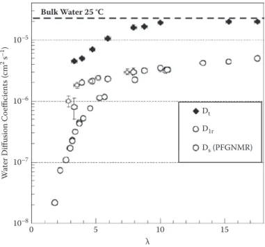
QENS studies on the dynamics in PEMs suggest that water and protons attain microscopic mobilities that are similar to those in bulk water. The experimental scattering data include two components, which correspond to “fast” (a few picoseconds) and “slow” (>100 ps) motions. The latter indicates the existence of the hydronium ion as a long-lived entity in Naion.87 The local and long-range diffusion coeficients of water, probed by QENS, range from Dt = 0.5 × 10⁻⁵ cm2 s–1 to Dt = 2.0 × 10⁻⁵ cm2 s–1 and Dlr = 0.1 × 10⁻⁵ cm2 s–1 to D
lr = 0.6 × 10⁻⁵ cm2 s–1 for water contents in the range of l ≈ 3–18.55 The diffusivity of protons in hydrated Naion 117, obtained from QENS data, is DH3O+ ≈ 0.5 × 10⁻⁵ cm2 s–1 at l = 15 and 300 K.55 The corresponding values of water and proton diffusivities in bulk water are 2.69 × 10⁻⁵ cm2 s–1 and 0.62 × 10⁻⁵ cm2 s–1, respectively.68
The reduction of the long-range diffusivity, Dlr, by a factor of four with respect to bulk water can be attributed to coninement and random mor-phology of the nanoporous network (i.e., effects of connectivity and tortu-osity of nanopores). For comparison, the water self-diffusion coeficient in Naion measured by PFG-NMR is Ds = 0.58 × 10⁻⁵ cm2 s–1 at l = 15.84,85 Notice that PFG-NMR probes mobilities over length scales > 0.1 mm. Comparison
of QENS and PFG-NMR studies thus reveals that the local mobility of water in Naion is almost bulk-like within the conined domains at the nanometer scale and that the effective water diffusivity decreases due to the channeling of water molecules through the network of randomly interconnected and tortuous water-illed domains.55
Figure 6.4 shows that long-range diffusivities of water in Naion mem-branes measured by QENS, Dlr, are equal to self-diffusivities determined by PFG-NMR, Ds, at l > 10. In well-hydrated membranes, the major geometric constraints for water mobility due to the phase-segregated, random network morphology of aqueous domains unfold at the scales probed by QENS, which is up to several tens of nanometers. This tells us that there are no restrictions of mobility arising between the nanometric and the micrometric scales when the membrane is suficiently hydrated. At low hydration, the difference between the two diffusion coeficients, Dlr and Ds, can be attributed to the lamellar struc-ture of Naion at the nanometric scale, as revealed by NMR relaxometry.87
The important impact of these experimental insights for molecular model-ing is that the development of structure versus property relations of PEM
10–5 Bulk Water 25 °C Dt D1r Ds (PFGNMR) 10–6 10–7 W at er D iff usion Co efficient s ( cm 2 s –1) 10–8 0 5 10 λ 15 FIGURE 6.4
Local (Dt) and long-range (Dlr) diffusion coeficients of water in Naion membrane probed
by QENS, illustrating the enhanced water dynamics with increasing hydration level of the membrane. Self-diffusivity of water in Naion probed by PFGNMR and self-diffusivity of bulk water (dashed horizontal line) are given for the sake of comparison. (We gratefully acknowl-edge permission of the authors to adopt this igure from Jean-Christophe Perrin, PhD thesis, 2006, Université Joseph Fourier, Grenoble, France.)
does not require multiscale approaches going all the way to the macroscopic scale. Rather, the main job is done if one arrives at the scale of several 10s of nanometers. Notably, operation at low hydration emphasizes even more the importance of (sub)nanoscale phenomena controlled by explicit interactions in the polymer–water–proton system.
6.5.3 Molecular Modeling of Self-Organization
Transport properties of hydrated PFSA ionomer membranes Naion strongly depend on nanophase-segregated morphology, water content, and state of water. In an operational fuel cell, these characteristics are indirectly deter-mined by the humidity level of the reactant streams and Faradaic current densities generated in electrodes, as well as the transport properties of cata-lyst layers, gas diffusion layers, and low ields.4,5,7,8,11,12,30,34
Despite satisfactory experimental evidence for cylindrical or ribbon-like shapes of backbone aggregates in Naion membranes, understanding of how transport properties are correlated with the microstructure is still lacking. Computer simulations at meso- to microscale and down to atomistic levels can complement experiments in understanding the processes of structural formation in Naion.5,88–96 The dilemma that molecular simulations are fac-ing is that suitable methods should allow includfac-ing microscopic details of chemical architecture and molecular interactions, while they should still capture the structure-related transport properties at long time and length scales.90,97 The length and time scales of full atomistic simulations, based on classical or ab initio molecular dynamics schemes, are usually limited by excessive computational demands.
Computational modeling approaches that have been developed to under-stand the structure and transport properties of water and protons in swollen Naion membranes89–91,98–104 include quantum mechanical,102–105 classical,91–94,97–101 and coarse-grained89,90 methods.
6.5.3.1 Atomistic Simulations
The earliest fully atomistic molecular dynamic (MD) studies of a simpliied Naion model using polyelectrolyte analogous103,106 showed the formation of a percolating structure of water-illed channels, which is consistent with the basic ideas of the cluster-network model of Hsu and Gierke.72 The irst MD simulations using a representation of the perluorosulfonate ionomer molecules by oligomers were performed by Vishnyakov and Neimark.93 In order to ensure a rapid approach to equilibrium, an annealing procedure was employed by applying a sequence of isobaric–isothermal (NPT) and canonical (NVT) simulation runs. By using a coarse-grained, united atom representation for the CFx groups in both the luorocarbon backbone and the side chains, Vishnyakov and Neimark improved the computational efi-ciency in their studies.
Au: pls supply missing word(s) between “membranes” and “Nafion”
Au: inserted “mo-lecular dynamic” as explanation of MD Au: should “analogous” be “analogs”?
United-atom force ields have the advantage that larger systems can be simulated compared to all-atom force ields. For instance, Urata et al.107 have simulated systems of united atoms CFx containing 12,000–25,000 atoms for 1.3–2.5 ns. A possible drawback that may arise from this representation is that the results do not account accurately for the role of backbones in control-ling morphology and transport. The all-atom approach is computationally more demanding, but it is required to establish rigorous benchmarks that can validate subsequent coarse-grained simulations.
Based on a structural analysis of the microphase-separated morpholo-gies, Vishnyakov and Neimark93 developed a similar structural picture of Naion to that obtained using earlier polyelectrolyte or oligomeric models. As a major new idea based on their molecular dynamics studies, they pro-posed that in the suficiently hydrated membrane, the continuous passage of protons and water molecules is effected by temporary bridges between water clusters that form and break dynamically on a time scale of 100 ps. However, this conjecture is dificult to reconcile with conductivity data and with the structural models discussed in Section 6.5.2 because it supplants the permanent percolating network of water pathways by transiently linked but otherwise disconnected water pools. Such a structural picture has impor-tant implications for water uptake as well. This peculiar model could be an artifact of the short oligomeric units that are have been used in these MD simulations.
Elliott et al.103 applied classical MD simulations to study the dynamics of small molecules in a model Naion membrane for l = 1, 3.8, and 9.7. They observed water segregation into “bound” water associated with the sul-fonate groups and more loosely attached “free” water.
Urata et al.107 used an explicit all-atom description of the fully dissociated side chains and a united-atom representation of backbones. Angular and torsional potential parameters and partial atomic charges were obtained from hybrid DFT and molecular orbital calculations. These authors observed that the sulfonate groups aggregated and shared water molecules at low l and that strong interactions with charged sulfonate groups suppressed the dynamics of water. At high l, frequent exchange occurred between bound and free water molecules. Moreover, the structure factors were calculated and compared with scattering data, showing that the molecular models give smaller ionic cluster sizes than those determined experimentally for PFSA membranes.
In a series of papers, Dupuis and co-workers99–101 simulated the effect of temperature and membrane hydration on membrane nanostructure and mobility of water and hydronium ions using classical MD simulations with DREIDING108 and modiied AMBER/GAFF109 force ields. In qualitative agree-ment with previous MD simulations, they showed that increasing l causes the sulfonate groups to drift apart. In their simulations, most of the water mol-ecules and hydronium ions are bound to the sulfonate groups at l < 7. This indicates that the simulation overestimates sulfonate–water interactions. Au: brought about
(“effected”) or receives impact of (“affected”)?
These studies showed that sulfonate groups surrounding the hydronium ion at low l sterically hinder the hydration of the hydronium ion. The inter-facial structure of sulfonate pendants in the membrane was studied by ana-lyzing structural and dynamical parameters such as density of the hydrated polymer; radial distribution functions of water, ionomers, and protons; water coordination numbers of side chains; and diffusion coeficients of water and protons. The diffusion coeficient of water agreed well with experimental data; for hydronium ions, the diffusion coeficient was found to be 6–10 times smaller than the value for bulk water.
Cui et al.98 performed similar analyses to those of Dupuis and co-workers. The side chain–side chain radial distribution functions (RDFs) reported by Cui et al. show remarkable qualitative deviation from those in Zhou et al.101 It is of note that the united atom approach used by Cui and co-workers ignored electrostatic interactions between CF2 groups of the polymeric backbone. This can lead to a poor description of the hydrated structure in the regions close to the polymeric backbones, unlike the all-atom force ield used in Zhou et al.101 For the sake of limited computational resources, Cui et al. used a relatively short representation of Naion ionomer chains consisting of three monomers as compared to the ten monomers used by Vishnyakov and Neimark91,93 or Urata et al.107 It can be expected that struc-tural correlations will strongly depend on this choice.
Jang et al.92 have used an all-atom approach in their MD simulation of phase segregation and transport in Naion at l = 16. It was shown that blocky Naion ionomers with highly nonuniform distributions of side chains on the polymer backbones form larger phase-segregated domains compared to systems with uniform distributions of side chains on the backbones. Water diffusion coef-icients at 300 and 353 K were found to agree well with experimental values.
In a recent effort, Elliot and Paddison104 applied QM/MM calculations (using the ONIOM110 method) to understand the effects of hydration on the local struc-ture of PFSA membranes. The calculations were performed on fragments of an SSC PFSA ionomer with three side chains. Full optimizations of the oligomeric fragment was carried out at the B3LYP/6-31G**:HF/3-21G** level with six to nine water molecules added. They reported a lowest energetic state with six water molecules. With more water molecules added, the energetic preference for uni-form hydration (interconnected water clusters) disappeared. The optimized structures of two oligomeric fragments at l = 2.5 showed that the structure with kinked backbone was energetically preferred (~37 kJ mol–1 lower in energy) over the one in which the luorocarbon backbone was fully extended.
Paddison and Elliott concluded that the conformation of the backbone, the side chain lexibility, and the degree of association and aggregation of the side chains under low hydration determine the formation of protonic species (Zundel and/or Eigen ions).104 These calculations for single ionomer chains do not account for ionomer aggregation. Therefore, they insuficiently repre-sent the membrane morphology and correlation effects between backbones, side chains, protons, and water.
6.5.3.2 Mesoscale Coarse-Grained Simulations
None of the architectures described before and used in atomistic molecular dynamic simulations is able to predict the structure-related properties of the membrane at long time (>10 ns) and length (>10 nm) scales. Mesoscale mod-els are needed to bridge the gap between the chemical structure of the poly-mer and the phase-segregated morphology of the self-organized membrane. The irst attempt for mesoscale simulations of hydrated Naion was based on a hybrid Monte Carlo (MC)/reference interaction site model (RISM).96 This method uses a combination of an MC routine and rotational isomeric state (RIS) theory developed originally by Flory.111 Later, Khalatur, Talitskikh, and Khokhlov96 used a highly coarse-grained representation in which each CF
2 or CF3 moiety was represented by a united atom, with a uniform distribution of side groups along the backbone.
The outcome of these calculations was that the water and polar sulfonic acid groups were found to be segregated into a three-layer structure with a central water-rich region and two outer layers of side groups strongly associ-ated with water molecules. In agreement with experiments,73 Khalatur and colleagues found a linear dependency of microscopic swelling on l, attrib-uted to the swelling of the voids between the ibrils.
Coarse-grained (CG) models based on dynamic self-consistent mean ield (SCMF) theory have recently been developed to study the structure of hydrated ionomers at varying l.89,90 Each side chain and backbone is con-structed of a number of CG segments (beads), which represent groups of several atoms. The interaction parameters and bead sizes were computed using classical atomistic MD method. In the SCMF approach, the density distributions of the mesoscopic beads, r(r), evolve under the inluence of a slowly varying external potential, U(r), relative to which polymer chains are equilibrated instantaneously. The main assumption of SCMF theory is that the external potential acting on the ideal system generates a density distribu-tion that matches that of the interacting system. The free energy funcdistribu-tional consists of terms for the beads in the external potential with the addition of a Gaussian coil-stretching term and it incorporates a Flory–Huggins type of mean ield mixing energy.
The bead–bead interaction parameters are generated using classical atomis-tic MD or they can be calculated from Flory–Huggins parameters.89,90,111–113 In general, variation of the hydration level at a ixed temperature leads to struc-tural reorganization of the phase-separated morphology.89,90 Simulations suggested that, at low water content (l < 6), the isolated hydrophilic domains are spherical, while at higher water content (l > 8), they deform into ellipti-cal shape. Because these levels of water content are signiicantly larger than the values required experimentally for achieving high bulk-like proton conductivity, it was concluded that there may be proton transport through water-depleted regions by interfacial diffusion or through a second ionic phase.
Another method applied to predict the mesoscopic structure of hydrated Naion membranes was dissipative particle dynamics (DPD), based as well on a CG model for Naion ionomer.112–114 In DPD simulations, the time evolu-tion for a set of interacting particles is governed by Newton’s equaevolu-tions.36,37 The total force acting on a particle entails contributions from a conservative force, a dissipative force, a pair-wise random force, and a binding spring force. Conservative interactions are parameterized on the basis of Flory– Huggins parameters. In agreement with SAXS measurements, Yamamoto and Hyodo114 showed in DPD simulations that the size and separation of ionic clusters increased approximately linearly with l. They also performed Lattice–Boltzmann (LB) simulations of water luxes in the membrane based on the morphologies generated by DPD. They showed that the permeability of the porous structure, extracted from Darcy’s law, increases with water con-tent and depends strongly on the pressure gradient, luid viscosity, and grid resolution.115
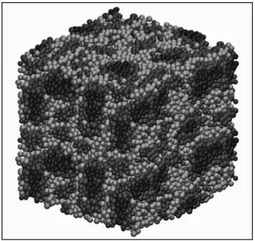
Recent DPD simulations by Vishnyakov and Neimark116 and Malek et al.117 provide the microsegregated structure of hydrated Naion at various l. A typi-cal structure obtained is depicted in Figure 6.5. By increasing l, the morphology
FIGURE 6.5
Snapshots of the inal microstructure at l = 9 (RH ≈ 94%), predicted by DPD calculations. Naion backbones are shown in red, the irst side-chain beads are shown in yellow, and the second side chain beads, water and hydronium ions are shown in blue. (M. Malek et al. Journal of Chemical
Physics 129 (2008) 204702.)
Au: pls revise; no color insert in book Au: inserted
λ—correct? Also, book has no color insert
of the membrane shows a percolation-type transition from isolated hydro-philic clusters to the three-dimensional network of randomly interconnected water channels. Very recently, Wu et al.118 applied extensive DPD simulations to study the morphologies of Naion, SSC, and 3M PFSA membranes at vari-ous hydration levels and ionomer equivalent weights. These DPD simulations suggested that 3M PFSA membranes exhibit larger water clusters compared to SSC membranes at the same water content. It was also shown that longer side chains lead to the formation of larger aggregates of sulfonate groups and consequently to larger water clusters, with cluster sizes varying from 2 to 13 nm for 5 < l < 16.118
In spite of many computational advantages, DPD and SCMF methods are not able accurately to predict physical properties that rely upon time correla-tion funccorrela-tions (e.g., diffusion), making them less applicable to extract struc-ture-related transport properties of phase-segregated membranes.
An alternative mesoscale approach for high-level molecular modeling of hydrated ionomer membranes is coarse-grained molecular dynamics (CGMD) simulations. One should notice an important difference between CGMD and DPD techniques. CGMD is essentially a multiscale technique (parameters are directly extracted from classical atomistic MD) and it has a different force ield handling scheme. Moreover, the angular and dihedral interactions in CGMD, which are ignored in DPD simulations, account for the conformational lexibility of ionomer molecules more appropriately.
In CGMD simulations, a model of the molecular system is deined in which spherical beads with predeined subnanoscopic length scale replace groups of atoms. Thereafter, parameters of renormalized interaction ener-gies between the distinct beads are speciied. In hydrated ionomer mem-branes, polar, nonpolar, and charged beads are distinguished in order to represent water, polymer backbones, anionic side chains, and hydronium ions.119 Interactions between beads could be determined by force matching procedures from atomistic interactions120,121 or from experimental structural correlation functions.119
In Malek et al.,117 clusters of four water molecules are represented by polar beads. Clusters of three water molecules and a hydronium ion correspond to charged beads. Each of these beads has a radius 0.43 nm and thus a volume of 0.333 nm3. A folded ionomer chain is shown in Figure 6.6. A side chain unit in Naion ionomer has a molecular volume of 0.306 nm3, which is comparable to the molecular volume (0.325 nm3) of a four-monomeric unit of polytetraluoroethylene PTFE (-[-CF2-CF2-CF2-CF2-CF2-CF2-CF2-CF2-]-. Each of the four monomeric units and each side chain (represented by a charged bead) are coarse-grained as spherical beads of volume 0.315 nm3. A coarse-grained chain of 20 apolar beads, as illustrated in Figure 6.6, replaces the hydrophobic backbone. This model, considered in Malek et al.,117 is the longest backbone chain in a CG mesoscale simulation so far.
Au: inserted “of the”
The interactions between nonbonded uncharged beads in CGMD simula-tions are modeled by the Lennard–Jones (LJ) potential:
U r r r LJ ij ij ij ( )= − 4 12 6 χ α α ,, (6.2)
where the effective bead radius (aij) is assumed as 0.43 nm for all beads at
which the interbead potential is zero. The strength of interactions cij could
assume ive possible values, ranging from weak (1.8 kJ/mol) to strong (5 kJ/ mol). Charged beads i and j interact via coulombic interactions:
U r q q r i j el i j ( )= . <
∑
(6.3)Interactions between chemically bonded beads in ionomer chains are mod-eled by harmonic potentials for the bond length and bond angle:
V r K r r V r K bond bond 0 angle angle ( ) ( ) ( ) [c = − = 1 2 1 2 2 oos( ) cos( )] ,θ − θ0 2 (6.4)
where the force constants are Kbond = 1,250 kJ mol–1 nm–2 and Kangle = 25 kJ mol–1, respectively.117,119 r
0 and q0 are the equilibrium bond length and angle, respectively. 119
FIGURE 6.6
Membrane simulations were performed with l = 4, 9, and 15.117 The meso-scopic structure of the hydrated membrane is visualized in Figure 6.7, reveal-ing a sponge-like structure similar to structures obtained by other mesoscale simulations.114–116 Together with hydrophilic beads of side chains, water beads form clusters that are embedded in the hydrophobic phase of the backbones. The detailed structural analysis indicates that the hydrophilic subphase is composed of a three-dimensional network of irregular channels. The typical channel sizes are from 1, 2, and 4 nm at l = 4, 9, and 15. This corresponds roughly to linear microscopic swelling.
The site–site RDF obtained from CGMD simulations matches very well to those from the atomistic MD simulations,117,120 as shown in Figure 6.8. The
3% wt W 6% wt W 19% wt W
FIGURE 6.7
Snapshots of the inal microstructure in hydrated Naion membrane at different water con-tents. Hydrophilic domains (water, hydronium, and side chains) are shown in green, while hydrophobic domains are shown in red.
Au: pls revise; no color insert in book 20 10 g (r) 0 0 1 r (nm) Atomistic-MD CG-MD 2 FIGURE 6.8
Site–site W–W radial distribution function obtained from CGMD simulation and compared with that of the atomistic MD simulation using the force-matching procedure.
RDF between the side chain beads and the other components of the mixture shows that side chains are surrounded with water and hydrated protons. The autocorrelation functions exhibit similar dependences on bead separa-tion at all l, even at very low relative humidity (RH), thus indicating a strong clustering of side chains due to the aggregation and folding of polymer backbones.122 The degree of ordering of water near polymer–water interfaces decreases with increasing l.117
So far, CG approaches offer the most viable route to the molecular mod-eling of self-organization phenomena in hydrated ionomer membranes. Admittedly, the coarse-grained treatment implies simpliications in structural representation and in interactions, which can be systematically improved with advanced force-matching procedures; however, it allows simulating systems with suficient size and suficient statistical sampling. Structural correlations, thermodynamic properties, and transport parameters can be studied.
Applied to PEMs, the analysis of simulated conigurations furnishes the structural picture of the self-organized, phase-segregated morphology of water channels conined by polymer aggregates. Sizes, shapes, and network properties of aqueous channels are in line with the accepted structural mod-els inferred from scattering experiments.74,75,80 Diameters of water channels vary in the range of 1–4 nm, exhibiting a roughly linear increase from low to high water content. The average separation of side chains increases as well with water content, indicating a continuous structural reorganization of polymer aggregates upon water uptake. This could involve backbones slid-ing along each other in order to adopt more stretched conformations.
The side chain separation varies in a range of 1 nm or slightly above. The network of aqueous domains exhibits a percolation threshold at a volume fraction of ~10%, which is in line with the value determined from conductiv-ity studies.24 This value is similar to the theoretical percolation threshold for bond percolation on a face-centered cubic lattice. It indicates a highly inter-connected network of water nanochannels. Notably, this percolation thresh-old is markedly smaller, and thus more realistic, than those found in atomistic simulations, which were not able to reproduce experimental values.
The ultimate goals of molecular modeling studies for PEM materials based on fully atomistic or CG models are to develop predictive mod-els that can be used for membrane material selection and to rationalize dependence in transport properties of water and protons upon changes in the hydration level. Although experiments provide empirical insights into the structural evolution upon water uptake and the transport proper-ties, for the sake of material design we must understand how the chemi-cal architecture affects properties and performance at the device level. Any individual simulation technique described in this section falls short in making exact predictions for the morphology and effective properties of PEM materials. Coarse-grained representations of ionomer chains uti-lized in mesoscale simulation techniques provide a means to overcome length- and time-scale limitations of atomistic simulations; however, the
accuracy of results of SCMF, DPD, and CG simulations hinges on appro-priate choices in deining the bead structure and the interaction param-eters between beads.
The requirements for self-consistent approaches in molecular modeling and computational materials science are (1) an appropriate structural repre-sentation of the primary polymer architecture, (2) an adequate treatment of molecular interactions between components, (3) a suficient size (in the range of 20–50 nm) of the simulated system that allows addressing effects of nano-scale coninement and random network morphology on transport of water and protons, and (4) a suficient statistical sampling of structural conigura-tions or elementary transport processes for reliable determination of thermo-dynamic properties and transport parameters. With respect to (1), it is vital that the length of monomeric sequences of the ionomer exceed the persistence lengths of the polymer backbone, which are between 3 and 5 nm.80
Steric and electrostatic effects of charged side chains ixed at the backbone will signiicantly enhance the stiffness of ionomer molecules. Overly sim-plistic (often, too short) representations of the ionomer chains could lead to largely inaccurate predictions of structure and properties. Atomistic mod-els often fail in reproducing sizes and shapes of water clusters and poly-mer aggregates as well as in predicting percolation properties and swelling behavior of the hydrated membrane because the monomeric sequences they utilize are too short.
The list of competing requirements deines the need for a multiscale model-ing framework. Startmodel-ing with quantum mechanical calculations at atomistic scale, one is able to develop simulation methodologies for proton transport and the resulting local electrostatic interactions to derive appropriate force ields for molecular dynamics simulations addressing larger scales. Built upon atomistic MD calculations, a coarse-grained or mesoscale descrip-tion is able to capture essential parameters in synthesis, characterizadescrip-tion, and development of advanced membrane materials for PEFCs at the relevant time and length scales.
6.6 Water Sorption in PEMs
6.6.1 Structure of Water in PEMs: Classification Schemes
As much as the nanophase segregated morphology of Naion has been a controversial issue in the literature over several decades, understanding the structure and distribution of water in PEMs has stimulated many efforts in experiment and theory. Major classiications of water in PEMs distinguish (1) surface and bulk water,7,8,24,30 (2) nonfreezable, freezable-bound, and free water,123–125 and (3) water vapor or liquid water.126–128 Another type of water often discussed is that associated with hydrophobic regions.