Publisher’s version / Version de l'éditeur:
Vous avez des questions? Nous pouvons vous aider. Pour communiquer directement avec un auteur, consultez la
première page de la revue dans laquelle son article a été publié afin de trouver ses coordonnées. Si vous n’arrivez pas à les repérer, communiquez avec nous à PublicationsArchive-ArchivesPublications@nrc-cnrc.gc.ca.
Questions? Contact the NRC Publications Archive team at
PublicationsArchive-ArchivesPublications@nrc-cnrc.gc.ca. If you wish to email the authors directly, please see the first page of the publication for their contact information.
https://publications-cnrc.canada.ca/fra/droits
L’accès à ce site Web et l’utilisation de son contenu sont assujettis aux conditions présentées dans le site LISEZ CES CONDITIONS ATTENTIVEMENT AVANT D’UTILISER CE SITE WEB.
Proceedings of Forum Acusticum 2005, pp. 1-5, 2005-08-01
READ THESE TERMS AND CONDITIONS CAREFULLY BEFORE USING THIS WEBSITE. https://nrc-publications.canada.ca/eng/copyright
NRC Publications Archive Record / Notice des Archives des publications du CNRC :
https://nrc-publications.canada.ca/eng/view/object/?id=dff3acd2-36a3-402d-a17c-5e1452d64d00 https://publications-cnrc.canada.ca/fra/voir/objet/?id=dff3acd2-36a3-402d-a17c-5e1452d64d00
NRC Publications Archive
Archives des publications du CNRC
This publication could be one of several versions: author’s original, accepted manuscript or the publisher’s version. / La version de cette publication peut être l’une des suivantes : la version prépublication de l’auteur, la version acceptée du manuscrit ou la version de l’éditeur.
Access and use of this website and the material on it are subject to the Terms and Conditions set forth at
On the distribution of transverse vibration in a periodic rib stiffened
plate
On the distribution of transverse vibration in a
periodic rib stiffened plate
Nightingale, T.R.T., Bosmans, I.
NRCC-48149
A version of this document is published in / Une version de ce document se trouve dans:
Proceedings of Forum Acusticum 2005, Budapest, Hungary,
Aug. 29-Sept. 2, 2005, pp. 1-5
On the distribution of transverse vibration in a periodic rib stiffened plate
Trevor R.T. NightingaleNational Research Council Canada, Institute for Research in Construction, Building M-27, Montreal Road, Ottawa, Ontario, K1A 0R6 CANADA
e-mail: trevor.nightingale@nrc.ca
Ivan Bosmans
LMS International, Engineering Services Division, Interleuvenlaan 68, B-3001 Leuven, Belgium
Floors in lightweight framed construction typically consist of wood sheathing and a series of joists spaced at a regular interval. The resulting system is a complex periodic orthotropic plate rib structure with point connections. The ability to accurately estimate the vibration response of the floor sheathing is critical to being able to predict flanking transmission paths involving the floor. This paper begins by presenting vibration data for an isotropic (Plexiglas) periodic plate rib system excited by a single point force. The depth of the ribs was systematically changed to assess the sensitivity of vibration transmission. The measured plate structure is modelled using an analytical solution for an assembly of finite-sized plate strips coupled at a series of parallel junctions. The paper concludes with a discussion of the agreement between measured and predicted results.
1 Introduction
To model the sound isolation in buildings one must be able to accurately predict the transmission of vibration energy from the source to the flanking junction and then from the flanking junction to the point of radiation. In lightweight framed constructions it cannot be assumed that the vibration response of a floor or wall surface will be uniform. Typically, there will be a strong gradient in the vibration energy density especially if the direction of propagation is perpendicular to the framing elements e.g., when the joists are parallel to a flanking junction involving the wall and floor. In this direction the energy appears localised near the source
The vibration response of pure periodic structures has been studied and efforts made to model them using several different approaches. It is often assumed that the system is one-dimensional which can be considered as the special case of normal incidence for a plate/rib structure [1], or if an arbitrary angle of incidence is permitted then only bending waves are considered [2]. The resulting simplified theories indicated the presence of stop bands where the travelling wave is attenuated exponentially with distance and pass bands where the structure has minimal effect.
It is very doubtful that framed constructions would appear to be purely periodic. There are two reasons. First the spacing between framing members is only nominal – the actual spacing between adjacent members will depend on many factors including workmanship, whether the length of the wall or floor is an integral multiple of the framing spacing, etc. Secondly, the sheathing (oriented strand board or plywood in the case of a floor, or gypsum board in case of a wall) is not homogeneous and isotropic. So the
wavenumber in the sheathing plate will vary slightly from location to location. A shift in the wavenumber is equivalent to a shift in distance because the phase angle is the product of distance and wavenumber. Thus it would be highly desirable to have a model that can predict the vibration response of an orthotropic structure with arbitrarily spaced ribs. This paper presents a summary of such a model and measured and predicted vibration levels are compared.
2 Theoretical
Model
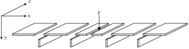
The ribbed plate is modelled as a number of plate elements coupled at a series of parallel junctions as shown in Figure 1. The plate to which the ribs are attached is considered to be formed from a series of smaller finite-sized plates defined by the plate/rib junctions. In this paper the portion of the plate between the ribs will be referred to as being the “bay”.
F
y x z
Figure 1: The ribbed plate is modelled by a series of finite-sized plates coupled at a number of parallel plate
junctions.
Thin plate theory is adopted so the effects of shear deformation and rotary inertia are not considered. Plate and ribs are treated similarly. Both are considered plate elements having a vibration response that can be described by a series expansion assuming simply supported boundary conditions along the plate edges perpendicular to the junction line as shown in Figure 2.
Forum Acusticum 2005 Budapest Nightingale, Bosmans
Z
X
Y
Simply supported boundary condition
Simply supported boundary condition
Arb itrar y bo unda ry c ondi tion Arb itra ry b ound ary c ondi tion v Lz
Figure 2: Boundary conditions applied to each plate. Uncoupled edges of the plate and ribs parallel to the z-direction are assumed to have free boundary conditions.
For a plate element parallel to the x-z plane, the solution is obtained by substitution of Eqn(1) into the equations of motion [3], [4]. t j z n x jk n
z
e
L
n
e
A
t
z
x
v
nπ
ω
=
∑
∞ =sin
)
,
,
(
1 (1)In the Eqn(1), v represents the plate displacement, An
the complex amplitude, kn the wavenumber in
x-direction and Lz the plate width in z-direction.
In the model each junction consists of two plates and a stiffening rib coupled by a junction beam. The boundary conditions at the junctions are described by equilibrium and continuity conditions for the equations of motion and are identical to those given elsewhere [5]. xp yp zp Fyp Fxp Fzp Mzp αzp ηp ζp ξp αzb ηb ζb ξb bay bay
junct ion beam
st iffening rib Lx
x0
y0
z0
Figure 3: Model of the joint showing forces, moments, and displacements used in the boundary conditions. The plate structure is driven by a point force normal to the plate surface, and as shown in Figure 1, the excitation is taken into account by introducing an additional junction at the driving point location. This helps evaluation of displacement and continuity conditions at the source.
In this paper the model approach will be referred to as “semi-modal finite plate” approach.
3 Measurement
Setup
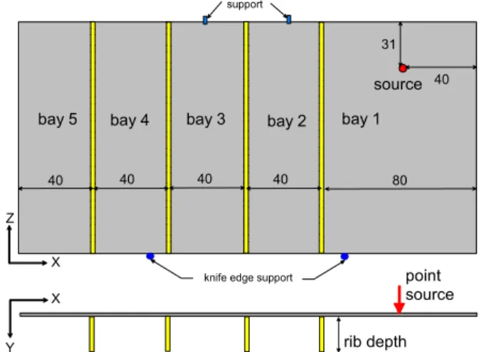
A simple well-defined structure was chosen for the initial evaluation of the model. Both the plate and the ribs were cut from Plexiglas, which is a homogeneous and isotropic material with well-characterized material properties [4]. The plate has dimensions 2.42x1.21m with a thickness of 11.9mm. This paper presents data for the case when four ribs were installed at the positions shown in Figure 4.
source bay 1 bay 2 bay 3 bay 4 support 40 31 80 40 40 40 40 point source rib depth
knife edge support
bay 5
Z
X
X
Y
Figure 4: Sketch showing the periodic structure used to evaluate the model. All dimensions are given in
centimetres.
Plexiglas ribs, 18.7 mm thick, divided the 1.2x2.4 m plate into five bays, four of which were nominally 40 cm wide and the bay containing the point source was 80 cm wide. Sixteen equally spaced bolts fastened each rib to the plate. This method has previously been shown to approximate a line connection [6] in the frequency range of interest (100-5000 Hz) when the screws are adequately torqued. The depth of the ribs was systematically changed to assess the effect of rib depth on propagation attenuation across the plate. The boundary conditions assumed in the model formulation are difficult to implement for the evaluation construction. The easiest to satisfy is the requirement for a free boundary at the uncoupled edge of a plate parallel to the global z-direction. This is achieved by mounting the plate vertically as shown in Figure 4. The simply supported boundary conditions for edges parallel to the x- and y-direction are very difficult to achieve and even more difficult to do without introducing indirect (flanking) transmission involving the mount. Flanking transmission will be most important at the high frequencies, while differences in the boundary condition will be most important at the low frequencies where there are low
Forum Acusticum 2005 Budapest Nightingale, Bosmans
order modes. Ensuring minimal flanking via the mounting was considered to be more important since flanking will potentially affect a considerably greater frequency range. Thus, to suppress flanking the specimen was rested on two knife-edge supports and the top edge supported at two points. It should be noted that this mount is expected to shift low-order modes of vibration for the ribs which plate and will introduce an error.
Velocity levels in third octave bands were measured in each bay using a scanning laser vibrometer – 138 points in each of the 40 cm wide bays and 276 points in the 80 cm wide bay. It was assumed that the internal loss factor of the plate could be approximated by the total loss factor when the plate did not have any ribs (i.e., that there were negligible losses at the four points supporting the plate). The power injection method was used to obtain loss factor estimates from measurements of plate average surface velocity and the injected power measured using an impedance head at the drive point.
4
Measured and Predicted Results
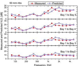
In this paper the accuracy of the semi-modal finite plate approach is gauged by comparing the measured and predicted velocity level difference (VLD) between the source bay (Bay 1) and each of the four receiving bays (Bays 2 through 5). Examination of the measured and predicted results using the finite plate model shown in Figure 5, Figure 6 and Figure 7 indicate that the prediction model successfully predicts the correct trend and magnitude. Results in the low frequencies are reasonably good despite the fact the test specimen boundary conditions Z=0 and Z=Lz are close to “free” when the model assumes “simply supported”. This effect is expected to become even less important and shift to lower frequencies as the dimension of the plate is increased in the z-direction.There are a number of important observations to be made from the measured VLD. The most obvious is that regardless of rib depth the VLD increases as the number of bays (and plate/rib junctions) separating source and receiver increases.
Closer inspection indicates that the greatest attenuation occurs at the first plate/rib junction; all subsequent junctions offer less attenuation. The same trend is also observed when all bays are the same width. This trend had also been observed in contour plots of wood joist floors [7]. 125 250 500 1k 2k 4k 0 10 20 300 10 20 300 10 20 300 10 20 30 35 Measured Predicted Frequency, [Hz] Bay 1 to Bay2 Bay 1 to Bay 3 Bay 1 to Bay 4 50 mm ribs Measured and Predicted VLD, [dB] Bay 1 to Bay 5
Figure 5: Measured and predicted VLD between source Bay 1 and indicated bay when the ribs are 50mm deep.
125 250 500 1k 2k 4k 0 10 20 30 0 10 20 30 0 10 20 30 0 10 20 30 40 Measured Predicted Frequency, [Hz] Bay 1 to Bay2 Bay 1 to Bay 3 Bay 1 to Bay 4 100 mm ribs Measured and Predicted VLD, [dB] Bay 1 to Bay 5
Figure 6: Measured and predicted VLD between source Bay 1 and indicated bay when the ribs are 100mm deep.
125 250 500 1k 2k 4k 10 20 30 40 50 10 20 30 40 50 10 20 30 40 50 10 20 30 40 50 Measured Predicted Frequency, [Hz] Bay 1 to Bay2 Bay 1 to Bay 3 Bay 1 to Bay 4 235 mm ribs Measured and Predicted VLD, [dB] Bay 1 to Bay 5
Figure 7: Measured and predicted VLD between source Bay 1 and indicated bay when the ribs are 235mm deep.
Forum Acusticum 2005 Budapest Nightingale, Bosmans
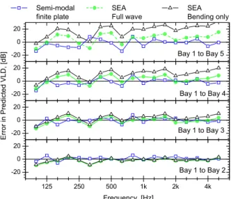
Unfortunately, the semi-modal finite plate model cannot be easily modified to turn-on or off a particular wave type to assess its importance. However, it is possible to compare the difference between measured and predicted results for two SEA predictions using proprietary SEA software [8] – one with all wave types considered, and the other where only bending is considered. In both cases the ribs are treated as plates. Figure 8 shows the error in VLD prediction for the 235mm deep rib case, also included is the error in the prediction for the semi-modal finite plate method.
-20 0 20 -20 0 20 -20 0 20 125 250 500 1k 2k 4k -20 0 20 Bay 1 to Bay 2 Bay 1 to Bay 3 Bay 1 to Bay 4
Semi-modal SEA SEA
finite plate Full wave Bending only
E rror in Predict ed V L D, [ d B ] Bay 1 to Bay 5 Frequency, [Hz]
Figure 8: Estimate of the standard error in the prediction over the building acoustics frequency range 100 through
5000 Hz. Data are given for the three rib depths. Examining the error in the prediction for the VLD between Bay 1 (source bay) and Bay 2 indicates that none of the methods have bias and all exhibit good agreement, although the finite plate model is slightly better. The important thing to note is that including wave types other than bending in the SEA model does not appreciably increase the accuracy of the VLD prediction between Bays 1 and 2. This is because attenuation at the first plate/rib junction is primarily due to bending.
Examining the errors in the predicted VLD for the other bays it can be seen that the SEA prediction for only bending waves begins to exhibit a bias – the VLD is consistently overestimated. With four junctions separating the source and receiver bays the error is typically 20 dB or more. Whereas, the SEA prediction that includes all wave types exhibits much better agreement with only a slight bias toward overestimation. This strongly suggests that there is high bending to bending attenuation at each junction which accounts for the high VLD at the first junction and that at successive junctions wave conversion from in-plane to bending plays prominently and is the dominant source for bending waves several junctions away from the source. The importance of in-plane waves for transmission paths involving several
junctions has previously been observed for buildings having reasonably homogeneous and isotropic construction [9]. 0 5 10 15 20 St andar d E rr or in Pr edict ion (1 00-5k Hz ), [ dB] Semi-Modal Finite Plate
Bay 1 to 2 Bay 1 to 3 Bay1 to 4 Bay 1 to 5
SEA Full Wave
SEA Bending Only
Figure 9: Estimate of the standard error in the predicted VLD for the three modelling approaches when predicting
the case with the 235mm deep beams. Figure 9 shows the standard error in the prediction for the range 100-5000 Hz for all three models when predicting the 235mm deep beam. From the figure it is evident that for all modelling approaches errors increase with increasing number of junctions between the source and receiving bays. The figure also shows that the semi-modal finite plate approach provides the most accurate prediction. If a standard error of approximately 7 dB can be tolerated then the SEA model where all wave types are considered would provide an adequate estimate for the first four bays. But the figure suggests that for subsequent bays the error will become quite large.
0 1 2 3 4 5 6 7 Stand ard Error in P rediction (100-5k H z ), [dB ] Rib: 50 mm
Bay 1 to 2 Bay 1 to 3 Bay1 to 4 Bay 1 to 5
Rib: 100 mm Rib: 235 mm
Figure 10: Estimate of the standard error in the prediction VLD for the semi-modal finite plate approach
for the frequency range 100 through 5000 Hz. Data are given for the three rib depths.
Forum Acusticum 2005 Budapest Nightingale, Bosmans
Figure 10 shows the standard error when the semi-modal finite plate approach is used to predict the VLD in the building acoustics frequency range (100 – 5000 Hz). The figure shows that the errors in the VLD prediction for the first bay are similar regardless of the depth of the rib. However, when there are two or more junctions separating the source and receive bays the error increases with both rib depth and number of junctions. For all rib depths, the most significant source of error occurs at the first junction where the level difference is due primarily due to attenuation of bending waves.
5 Summary
This paper has presented a prediction model that uses finite plates with a semi-modal approach to predict a periodic structure where the ribs needed not be perfectly periodic (i.e., spaced a uniform distance apart). The model is shown to accurately predict a homogeneous and isotropic periodic structure. Measured and predicted VLD’s showed that in general there is more attenuation at the first junction than at subsequent junctions. This is because transmission from bending to bending is weak at each junction while there is significant wave conversion from in-plane to bending due to the eccentric nature of the junctions. Consequently, a model that assumes pure bending will significantly overestimate the VLD when the source and receive bays are separated by several junctions. Surprisingly, a full wave model of the junction used in an SEA model produced quite good results although errors tended to increase much more rapidly with the number of junctions than was observed for the semi-modal finite plate model.
References
1 Jonas Brunskog, 2005, “A wave approach to structural transmission in periodic structures: Thin beam case,” Acta Acustica, Vol.91, pp. 91-102. 2 Y.K. Tso and C.H. Hansen, 1998, “The transmission of vibration through a coupled periodic structure,”
Journal of Sound and Vibration, Vol. 215(1), 63-79.
3 E. Rébillard and J.-L. Guyader, 1995, “Vibrational behaviour of a population of coupled plates:
hypersensitivity to the connexion angle”, Journal of
Sound and Vibration, 188(3), 435-454.
4 I. Bosmans 1998 Analytical Modelling of Structure-Borne Sound Transmission and Modal Interaction at Complex Plate Junctions. PhD Dissertation, KU Leuven, Belgium.
5 I. Bosmans, T.R.T. Nightingale, 2001,“Modeling vibrational energy transmission at bolted junctions between a plate and a stiffening rib," Journal of the
Acoustical Society of America, Vol. 109(3), pp.
999-1010
6 S. Schoenwald, T.R.T. Nightingale, 2000, "Measurement of structural intensity on plate structures," Canadian Acoustics, Vol. 29(3),
September, Proceedings Issue of Canadian Acoustics, pp. 102-103.
7 T. R. T. Nightingale, R. E. Halliwell, J. D. Quirt, 2002, “Effectiveness of toppings to control flanking transmission in lightweight constructions”,
Proceedings of Forum Acusticum, Sevilla 2002, RBA-CIB-009-IP, pp. 1-6.
8 Free SEA 0.91 (2004) Ennes Sarradj Technische Universitat Dresden, Germany
9 R.J.M. Craik and A. Thancanamootoo, 1992, “The importance of in-plane waves in sound transmission through buildings,” Applied Acoustics. 37, pp. 85-109.