Publisher’s version / Version de l'éditeur:
Special edition of the FS-World magazine on the 4th International Symposium on Tunnel Safety and Security (ISTSS), Spr, pp. 30-35, 2010-03-01
READ THESE TERMS AND CONDITIONS CAREFULLY BEFORE USING THIS WEBSITE. https://nrc-publications.canada.ca/eng/copyright
Vous avez des questions? Nous pouvons vous aider. Pour communiquer directement avec un auteur, consultez la première page de la revue dans laquelle son article a été publié afin de trouver ses coordonnées. Si vous n’arrivez pas à les repérer, communiquez avec nous à PublicationsArchive-ArchivesPublications@nrc-cnrc.gc.ca.
Questions? Contact the NRC Publications Archive team at
PublicationsArchive-ArchivesPublications@nrc-cnrc.gc.ca. If you wish to email the authors directly, please see the first page of the publication for their contact information.
NRC Publications Archive
Archives des publications du CNRC
This publication could be one of several versions: author’s original, accepted manuscript or the publisher’s version. / La version de cette publication peut être l’une des suivantes : la version prépublication de l’auteur, la version acceptée du manuscrit ou la version de l’éditeur.
Access and use of this website and the material on it are subject to the Terms and Conditions set forth at Emergency ventilation strategies in a roadway tunnel
Kashef, A.
https://publications-cnrc.canada.ca/fra/droits
L’accès à ce site Web et l’utilisation de son contenu sont assujettis aux conditions présentées dans le site LISEZ CES CONDITIONS ATTENTIVEMENT AVANT D’UTILISER CE SITE WEB.
NRC Publications Record / Notice d'Archives des publications de CNRC: https://nrc-publications.canada.ca/eng/view/object/?id=01beb57a-68a2-4724-8ae6-58f7ff811130 https://publications-cnrc.canada.ca/fra/voir/objet/?id=01beb57a-68a2-4724-8ae6-58f7ff811130
http://www.nrc-cnrc.gc.ca/irc
Em e rge nc y ve nt ila t ion st ra t e gie s in a roa dw a y t unne l
N R C C - 5 3 2 8 2
K a s h e f , A .
M a r c h 2 0 1 0
A version of this document is published in / Une version de ce document se trouve dans:
Special edition of the FS-World magazine on the 4th International Symposium on Tunnel Safety and Security (ISTSS), Spr, pp. 30-35, March 01, 2010
The material in this document is covered by the provisions of the Copyright Act, by Canadian laws, policies, regulations and international agreements. Such provisions serve to identify the information source and, in specific instances, to prohibit reproduction of materials without written permission. For more information visit http://laws.justice.gc.ca/en/showtdm/cs/C-42
Les renseignements dans ce document sont protégés par la Loi sur le droit d'auteur, par les lois, les politiques et les règlements du Canada et des accords internationaux. Ces dispositions permettent d'identifier la source de l'information et, dans certains cas, d'interdire la copie de documents sans permission écrite. Pour obtenir de plus amples renseignements : http://lois.justice.gc.ca/fr/showtdm/cs/C-42
1 Dr. Kashef is a senior research officer at the Fire Research Program at the National Research Council of Canada and an adjunct professor at Carleton University. Dr. Kashef has over 15 years extensive hands-on applying numerical and experimental techniques in a wide range of engineering applications including fire dynamics, tenability, heat transfer and smoke transport in the built environment and transportation systems. He is the author of numerous publications and is a member of ASHRAE, NFPA 502, PIARC WG 4 and a Registered Professional Engineer in the Province of Ontario.
Emergency Ventilation Strategies in a Roadway Tunnel
Ahmed Kashef
National Research Council of Canada, Institute for Research in Construction, 1200 Montreal Road, Bldg. M59, Ottawa, Ontario K1A 0R6 Canada
ABSTRACT
A research study was conducted at the National Research Council of Canada to evaluate the effect of different parameters on the performance of the emergency ventilation system in the event of a fire in a newly-constructed section of a road tunnel. The parameters included: tunnel cross-section width and height, tunnel slope, fire size and location, meteorological conditions, and mode of fans operation. This study aimed at assessing the ability of in-place emergency ventilation strategies to control smoke spread and minimize its impact on tunnel users using both numerical and experimental approaches.
In total, four field fire experiments and seven numerical simulations were conducted. The field measurements included the measurements of temperature, airflow speed and smoke optical density. Based on the study, recommendations were made to optimize the ventilation strategies in the tunnel section. This article presents the details of the study as well as the recommendations made.
INTRODUCTION
The provision of a safe egress route that is free of smoke and hot gases is the main objective for a tunnel Emergency Ventilation System (EVS). Methods of controlling contaminants and smoke from a fire in a tunnel using EVS include longitudinal airflow, smoke extraction and smoke dilution. In the event of a fire, the phenomenon of “backlayering” should be controlled. The backlayering phenomenon was defined as the situation in which the smoke moves against the airflow provided by the ventilation system upstream of the fire creating an environment that poses a danger to both tunnel users and emergency responders. Many parameters influence the smoke flow and its stratification. These include: heat release rate (fire size), tunnel length, cross-section and grade, traffic flow, meteorological conditions and fire protection systems. Establishing airflow requirements for roadway tunnels and consequently the capacity of the EVS is a challenging task due to the difficulty of controlling many variables (e.g. changes in traffic patterns and modifications to the tunnel).
This article describes the conducted in-situ fire tests and presents test measurements used to provide the initial and boundary conditions for the Computational Fluid Dynamics (CFD) simulations. The CFD simulations were conducted using a fire load of 20 MW [1]. Based on this study, optimized ventilation strategies were recommended for the investigated tunnel section.
The investigated tunnel section was 305 m long and runs from west to east. The section was composed of the existing tunnel and the new part, 232 m long, which extended up to the east portal and ran under a newly constructed building. The new tunnel section had 5 lanes with traffic flow from west to east. The clear height of the tunnel changes as the floor of the tunnel had an up-slope from west to east (Figure 1). The section is characterized with large cross-beams which obstructed the airflow from the wall vents and ducts of the EVS.
Figure 1. Investigated tunnel section.
Three sets of fans were used to provide ventilation in the investigated tunnel section. The tunnel first set (SET I) was located in the existing tunnel section (0 m and 72 m from west) and provided fresh air through ceiling vents. The new section had longitudinal ventilation scheme that included two sets of reversible fans (SET II and SET III). SET II and SET III supplied/exhausted air through wall louvers and ducts, respectively.
EXPERIMENTAL STUDY
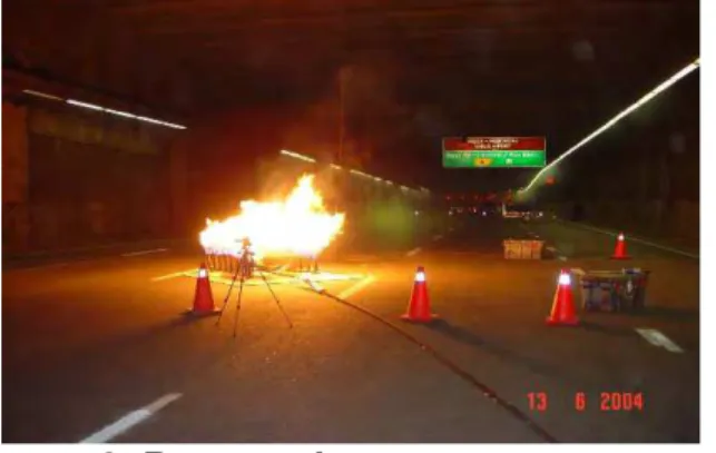
Four full-scale fire tests: “Test 1”, “Test 2”, “Test 3”, and “Test 4” corresponding to four emergency ventilation scenarios: “VentSc 1”, “VentSc 2”, “VentSc 3”, and “VentSc 4”, were conducted using a clean-burning, compact, portable propane burner that generated minimal visible smoke and was capable of producing up to 5 MW of heat output simulating a small vehicle. The burner was equipped with systems for immediate shutdown (Figure 2). Artificial smoke was added for visualization purposes. The fire size was varied depending on the ventilation scenario to limit the temperature at the tunnel ceiling to below 100°C. The four tests fire sizes were approximately: 2, 4, 3, and 4 MW, respectively. The four fire tests were conducted in about 9 h overnight to minimize traffic disruptions.
The instrumentation packages used in the on-site fire experiments were designed to be portable and readily set-up in a limited time frame. Six two-person teams conducted the four tests and recorded temperature and optical smoke density (SOD) measurements at three locations (Drops 1, 2 and 3) downstream of the fire with 26 points of measurements. The SOD indicated the level of smoke obscuration and hence the level of visibility in the tunnel.
Figure 2. Propane burner system.
Upstream was defined in the context of this article as the direction from which the traffic entered the tunnel.
A thermocouple tree of 12 thermocouples (5 vertical thermocouples and 7 ceiling thermocouples) was installed at the fire location, Drop 1 (Figure 3a). Two other thermocouples trees, each containing 7 thermocouples, were installed at Drops 2 and 3. SOD values were measured at 4 locations downstream of the fire at Drops 2 and 3, Figure 3c. Air speeds were measured at the fire location, east portal, Beams (B1, B2, B3), fan ducts, and at several cross-sections of the tunnel.
No backlayering was observed during the tests except for Test 1 and Test 4 where some smoke was observed close to the interface section between the old and new sections. However, the fire size was limited to 4 MW. The tests revealed strong turbulent flow conditions around the three beams as a result of the ventilation flows impacting on them. The full scale in-situ fire tests (Figure 4) concluded that VentSc 2, with the three sets of fans operate in supply mode, was the most effective scenario in eliminating smoke. Measured airflow values for Test 1, at the interface between the old and new tunnel sections, were relatively small (which was lower than the natural ventilation flow). This was most likely due to large pressure losses in the fans plenum. Maximum SOD values were measured close to the ceiling indicating that most of the smoke traveled close to the ceiling.
(a) Drop 1 (b) Drops 2 & 3 (c) Drops 2 & 3
Figure 3. Thermocouple tree and SOD measurements at Drops 1, 2 and 3.
(a) Maximum temperatures at Drop 2 (b) Maximum temperatures at Drop 1
(c) Maximum SOD at Drop 2 (d) Maximum SOD at Drop 3
(e) Average airflow speeds at East Portal
NUMERICAL STUDY
The study employed the Fire Dynamic Simulator (FDS) CFD model [5] for the simulation of the behavior of the smoke originating from fires in the tunnel section. Large fire sizes were not feasible for testing in the tunnel due to the risk of damage to the tunnel and its support systems. Therefore, a 20 MW gasoline pool fire (equivalent to a bus or truck on fire) was used to conduct all numerical simulations. It was assumed that the gasoline fuel (C16H34) was being burned with constant yields of CO (0.131) and Soot (0.360) [4]. RESULTS AND DISCUSSIONS
CFD Simulations of the EVS in the Supply Mode
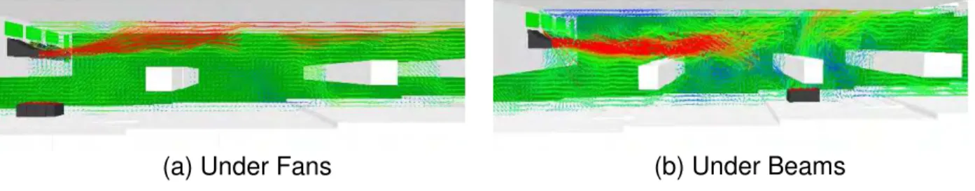
To investigate the performance of EVS operating in supply mode during large fires, Ventilation VentSc 2 was used in the numerical simulations of four fire locations. One at the interface of the old/new tunnel section (“Under Fans” fire scenario); under the second beam “Under Beams”; at a distance of 172 m from the west “DIST 172” and at a distance of 247 m from the west “DIST 247”.
“Under Fans”: Figure 5a shows the resulting velocity vector field due to the fire. The
figure shows less area of reversed flow exists under the beams. The resulting smoke surface is shown in Figure 6a and the associated visibility is shown in Figure 7a. The figures indicate that there was no backlayering in the old section of the tunnel and that all the smoke moved towards the east portal in the direction of the traffic. In this case, SET I created an air curtain that prevented smoke from moving upstream of the fire.
(a) Under Fans (b) Under Beams
Figure 5. Velocity vectors of different Fire Scenarios – VentSc 2.
Under Beams Fire Scenario: Figure 5b shows the resulting velocity vector field due to
the fire. The figure shows less area of reversed flow exists under the beams. The resulting smoke surface and the associated visibility are shown in Figures 6b and 7b. The figures indicate that there was no backlayering in the old section of the tunnel and that all the smoke moved towards the east portal in the direction of the traffic.
DIST 172 Fire Scenario: The resulting smoke surface is shown in Figure 6c and the
associated visibility is shown in Figure 7c. The figures indicate that backlayering of smoke occurs at a distance of about 70 m upstream of the fire in the area between the fire source and the last beam (B3).
(a) Under Fans (b) Under Beams
(c) DIST 172 (d) DIST 247
Figure 6. Smoke spread of different Fire Scenarios – VentSc 2.
DIST 247 Fire Scenario: In this case, the average airflow velocity at the fire was
predicted to be about 2 m/s (greater than the critical velocity to prevent smoke backlayering, 1.7 m/s). The resulting smoke surface and the associated visibility are shown in Figures 6d and 7d. The figures indicate that backlayering of smoke occurred at a short distance of about 30 m upstream of the fire as a result of the reversed airflow in this region. In this region, the average visibility Dropped to about 15 m.
(a) Under Fans (b) Under Beams
(c) DIST 172 (d) DIST 247
CFD Simulations of the EVS in the Exhaust Mode
As demonstrated in the previous section, operating the EVS in the supply mode produced untenable environment conditions upstream of the fire for the two fire scenarios: “Under Beams” and “DIST 172”. With the high ceiling at this section of the tunnel, the possibility of keeping smoke and hot gases at high elevations was investigated by operating the two sets of fans “SET 2” and “SET 3” in the exhaust mode for three fire locations: Under Beams, at 172 m and 247 m.
“Under Beams”: Fresh air was drawn to the fire location from upstream and
downstream of the fire. In this case, the ceiling jet flow is mainly directed towards the exhaust fans as a result of higher exhaust capacity. The resulting smoke surface and the associated visibility are shown in Figures 8a and 8b. The smoke and hot gases were kept at a level above the three Beams and a 20 m visibility or higher was maintained upstream of the fire.
(a) Smoke spread
(b) Visibility along the tunnel
Figure 8. Under Beam Fire Scenario.
“DIST 172”: The resulting smoke surface and the associated visibility are shown in
Figures 9a and 9b. The smoke was kept at a level above the three Beams with the visibility upstream of the fire maintained at 20 m.
(a) Smoke spread
(b) Visibility along the tunnel
Figure 9. DIST 172 fire scenario.
“DIST 247”: In this case, fresh air was mainly drawn to the fire location from upstream
of the fire. Downstream of the fire, airflow was primarily directed towards the east portal. At 72 m from west and due to the remote position of the fire from this location, most of the exhausted airflow was drawn from the old tunnel section impending airflow moving in the east-west direction. This, in turn, limited the ability of this ventilation scenario to remove smoke (Figure 10), and as a result the smoke layer descended below the three Beams, reducing the average visibility to lower than 20 and 15 m upstream and downstream of the fire, respectively.
(a) Smoke spread
(b) Visibility along the tunnel
CONCLUSIONS AND RECOMMENDATIONS
With the EVS Operating in the supply mode, four fire locations were simulated with one ventilation scenario. The performance of the ventilation fans in the supply mode was significantly affected by large pressure losses in the fans plenum and the large beams that obstructed the airflow and created strong turbulent flow conditions. Backlayering phenomenon was predicted for two fire locations close to the fans location. At locations further away from the exhaust fan, where the airflow speed was greater than the critical velocity, the supply mode may be used to maintain tenable conditions upstream of fire. To improve the performance of the ventilation fans in the supply mode, it was recommended to reduce airflow losses in the fans plenum and to increase and direct airflow in such a way as to avoid impacting on the large beams and losing momentum, e.g. using ducts that would better direct the flow away from the beams. Another possible remedial measure was to install jet fans under the beams to enhance the airflow in this section.
With the high ceiling of this section of the tunnel, the possibility of keeping smoke and hot gases at high elevations was investigated by operating the EVS in the exhaust mode. In this case, the activated ventilation scenarios were able to maintain a tenable environment in the tunnel upstream of the fire up to the fire source being located at 172 m from the west. At locations further away from the exhaust fan, the exhaust mode was not effective in maintaining tenable conditions in the tunnel new section.
REFERENCES
1. National Fire Protection Association, "NFPA 502 Standard for Road Tunnels, Bridges, and Other Limited Access Highways", 2008 Edition, NFPA, Quincy, MA. 2. Kashef, A., and Saber, H. H. “Simulation of Fires in the New Section under the
Palais Des Congrès of the Way B in the East Direction of the Ville-Marie Tunnel”, National Research Council Canada, Report B4540. January 2005.
3. Klote, J., and Milke, J., “Principles of Smoke management,” ASHRAE, Inc., 1791 Tullie Circle NE, Atlanta, GA 30329, 2002.
4. PIARC Committee on Road Tunnels, “Fire and Smoke Control in Road Tunnels” PIARC – World Road Association, 1999.
5. McGrattan, K. B., Baum, H. R., Rehm, R. G., Forney, G. P., Floyd, J. E., Hostikka, S., Fire Dynamics Simulator (Version 4), Technical Reference Guide (Technical Report NISTIR 6783), National Institute of Standards and Technology, Gaithersburg, Maryland, Sep. 2003.