Publisher’s version / Version de l'éditeur:
Vous avez des questions? Nous pouvons vous aider. Pour communiquer directement avec un auteur, consultez la première page de la revue dans laquelle son article a été publié afin de trouver ses coordonnées. Si vous n’arrivez pas à les repérer, communiquez avec nous à PublicationsArchive-ArchivesPublications@nrc-cnrc.gc.ca.
Questions? Contact the NRC Publications Archive team at
PublicationsArchive-ArchivesPublications@nrc-cnrc.gc.ca. If you wish to email the authors directly, please see the first page of the publication for their contact information.
https://publications-cnrc.canada.ca/fra/droits
L’accès à ce site Web et l’utilisation de son contenu sont assujettis aux conditions présentées dans le site LISEZ CES CONDITIONS ATTENTIVEMENT AVANT D’UTILISER CE SITE WEB.
Inter-noise 2006 [Proceedings], pp. 1-10, 2006-12-03
READ THESE TERMS AND CONDITIONS CAREFULLY BEFORE USING THIS WEBSITE. https://nrc-publications.canada.ca/eng/copyright
NRC Publications Archive Record / Notice des Archives des publications du CNRC : https://nrc-publications.canada.ca/eng/view/object/?id=1f53c0a2-a70c-4a85-a3ea-2de13035b907 https://publications-cnrc.canada.ca/fra/voir/objet/?id=1f53c0a2-a70c-4a85-a3ea-2de13035b907
NRC Publications Archive
Archives des publications du CNRC
This publication could be one of several versions: author’s original, accepted manuscript or the publisher’s version. / La version de cette publication peut être l’une des suivantes : la version prépublication de l’auteur, la version acceptée du manuscrit ou la version de l’éditeur.
Access and use of this website and the material on it are subject to the Terms and Conditions set forth at
On the drive-point mobility of a periodic rib-stiffened plate
http://irc.nrc-cnrc.gc.ca
O n t h e d r i v e p o i n t m o b i l i t y o f a p e r i o d i c r i b
-s t i f f e n e d p l a t e
N R C C - 4 5 6 0 9
N i g h t i n g a l e , T . R . T . ; B o s m a n s , I .
A v e r s i o n o f t h i s d o c u m e n t i s p u b l i s h e d i n
/ U n e v e r s i o n d e c e d o c u m e n t s e t r o u v e
d a n s : I n t e r - N o i s e 2 0 0 6 , H o n o l u l u , H a w a i i ,
D e c . 3 - 6 , 2 0 0 6 , p p . 1 - 1 0
INTER-NOISE 2006
3-6 DECEMBER 2006 HONOLULU, HAWAII, USA
On the drive-point mobility of a periodic rib-stiffened plate
Trevor R.T. NightingaleNational Research Council Canada, Institute for Research in Construction, Building M-27, Montreal Road, Ottawa, Ontario,
K1A 0R6 Canada
Ivan Bosmans
LMS International, Engineering Services Division, Interleuvenlaan 68, B-3001 Leuven,
Belgium
ABSTRACT
Floors in lightweight framed construction typically consist of wood sheathing and a series of joists spaced at a regular interval. The resulting system is a complex periodic orthotropic plate rib structure with point connections. The ability to accurately estimate the power injected by impact sources, and the resulting vibration response of the floor, is critical to being able to predict flanking transmission for sources of structural excitation, such as footfalls, washers, dryers, etc. This paper presents measured and predicted mobilities, and vibration levels, for a point-excited plate-rib system constructed from an isotropic material (Plexiglas). It begins by showing there is significant variation in the drive point mobility. The mobility is shown to be sensitive to the number of ribs on the plate in addition to the distance from the drive point to the nearest ribs. Thus, ordinary mobilities for an infinite plate and beam are inadequate to accurately model the system. An analytical solution for an assembly of finite-sized plate strips coupled at a series of parallel junctions is presented and used to model the plate-rib structure. There is good agreement between measured and predicted results for the drive point mobility as well as the vibration levels.
1 INTRODUCTION
To model the impact sound isolation in buildings one must be able to accurately predict the power injected by the source, the transmission of vibration energy from the point(s) of excitation to the flanking junction, and transmission from the flanking junction to the point of radiation. In lightweight framed constructions it cannot be assumed that the vibration response of a floor or wall surface will be uniform. Typically, there will be a strong gradient in the vibration energy density especially if the direction of propagation is perpendicular to the framing elements e.g., when the joists are parallel to a flanking junction involving the wall and floor. In this direction the energy appears localised near the source
The vibration response of pure periodic structures has been studied and efforts made to model them using several different approaches. It is often assumed that the system is one-dimensional which can be considered as the special case of normal incidence for a plate/rib structure [ ]1 , or if an arbitrary angle of incidence is permitted then only bending waves are considered [2]. The resulting simplified theories indicated the presence of stop bands (where the travelling wave is attenuated exponentially with distance) and pass bands (where the structure has minimal effect).
It is very doubtful that framed constructions would appear to be purely periodic. There are two reasons. First, the spacing between framing members is only nominal – the actual spacing between adjacent members will depend on many factors including workmanship, and the length of the wall or floor may not be an integral multiple of the framing spacing, etc. Secondly, the sheathing (oriented strand board or plywood in the case of a floor, or gypsum board in case of a wall) is not homogeneous and isotropic. Therefore, the wavenumber in the sheathing plate will vary slightly from location to location. A shift in the wavenumber is equivalent to a shift in distance because the phase angle is the product of distance and wavenumber.
Thus, it would be highly desirable to have a model that can predict the vibration response of an orthotropic structure with arbitrarily spaced ribs. This paper presents a summary of such a model and measured and predicted vibration levels are compared.
2 THEORY
The ribbed plate is modelled as a number of plate elements coupled at a series of parallel junctions as shown in Figure 1. The plate to which the ribs are attached is considered to be formed from a series of smaller finite-sized plates defined by the plate/rib junctions. In this paper the portion of the plate between the ribs will be referred to as being the “bay”.
F
y x z
Figure 1: The ribbed plate is modelled by a series of finite-sized plates coupled at a number of parallel plate
junctions.
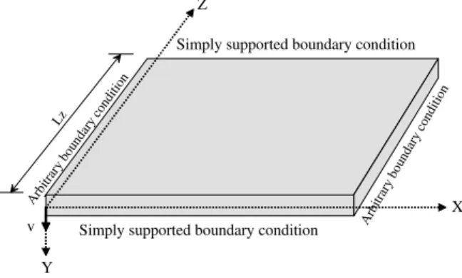
Thin plate theory is adopted so the effects of shear deformation and rotary inertia are not considered. Plate and ribs are treated similarly. Both are considered plate elements having a vibration response that can be described by a series expansion assuming simply supported boundary conditions along the plate edges perpendicular to the junction line as shown in Figure 2.
Z
X
Y
Simply supported boundary condition
Simply supported boundary condition
Arb itrar y bo unda ry c ondi tion Arb itra ry b ound ary c ondi tion v Lz
Figure 2: Boundary conditions applied to each plate.
Uncoupled edges of the plate and ribs parallel to the z-direction are assumed to have free boundary conditions. For a plate element parallel to the x-z plane, the solution is obtained by substitution of Eqn(1) into the equations of motion [3], [4]
t j z n x jk n z e L n e A t z x v n π ω ⎟⎟ ⎠ ⎞ ⎜⎜ ⎝ ⎛ =
∑
∞ = sin ) , , ( 1 (1)In the Eqn(1), v represents the plate displacement, An the complex amplitude, kn the
wavenumber in x-direction and Lz the plate width in z-direction.
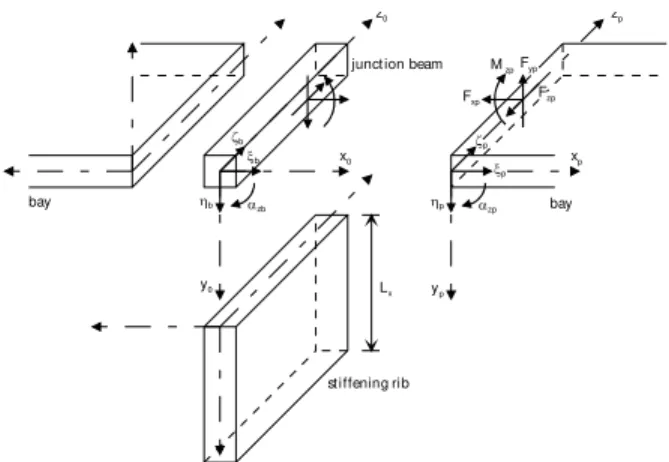
In the model each junction consists of two plates and a stiffening rib coupled by a junction beam. The boundary conditions at the junctions are described by equilibrium and continuity conditions for the equations of motion and are identical to those given elsewhere [5].
xp yp zp Fyp Fxp Fzp Mzp αzp ηp ζp ξp αzb ηb ζb ξb bay bay
junct ion beam
st iffening rib Lx
x0
y0
z0
Figure 3: Model of the joint showing forces, moments, and displacements used in the boundary conditions.
The plate structure is driven by a point force normal to the plate surface, and as shown in Figure 1, the excitation is taken into account by introducing an additional junction at the driving point location. This helps evaluation of displacement and continuity conditions at the source.
In this paper the model approach will be referred to as “semi-modal finite plate” approach.
3 MEASUREMENT SETUP
A simple well-defined structure was chosen for the initial evaluation of the model. Both the plate and the ribs were cut from Plexiglas, which is a homogeneous and isotropic material with well-characterized material properties [4]. The plate has dimensions 2.42x1.21m with a thickness of 11.9mm. Plexiglas ribs, 18.7 mm thick, nominally spaced 40 mm on center, divided the 1.2x2.4 m plate into bays as shown in Figure 4 and Figure 7. Sixteen equally spaced bolts fastened each rib to the plate. An examination of the structural intensity vectors suggested this number of bolts would adequately approximate a line connection [6] in the frequency range of interest (100-5000 Hz) with sufficiently torqued bolts.
source
bay 1 bay 2 bay 3 bay 4
44 31 80 40 40 40 40 point source rib depth point support bay 5 Z X X Y
Rib 2 Rib 3 Rib 4 Rib 5
Figure 4: Sketch showing the periodic structure used to evaluate the model. All dimensions are given in centimetres.
The boundary conditions assumed in the model formulation can be difficult to implement for the evaluated construction. The easiest to satisfy is the requirement for a free boundary at the uncoupled edge of a plate parallel to the global z-direction. This is achieved by mounting the plate vertically as shown in Figure 4. The simply supported boundary conditions for edges parallel to the x- and y-direction are difficult to achieve in practice. Gibbs and Shen [7] encountered similar difficulties and eventually decided to validate their calculation model with boundary conditions representing an intermediate case between clamped and simply supported. Even if it would be practically possible to create simply supported boundary conditions, it would be difficult to do so without introducing indirect (flanking) transmission involving the mount. Flanking transmission will be most important at the high frequencies where a high velocity level difference is expected across the plate. Differences in the boundary condition will be most important at the low frequencies where there are low order modes. Ensuring minimal flanking via the mounting was considered more important since flanking will potentially affect a considerably greater frequency range. Thus, to suppress flanking the specimen was rested on two knife-edge supports and the top edge supported at two points.
4 MEASURED AND PREDICTED VELOCITY LEVELS
In this paper the accuracy of the semi-modal finite plate approach is gauged by comparing the measured and predicted velocity level difference (VLD) between the source bay (Bay 1) and each of the four receiving bays (Bays 2 through 5) shown in Figure 4.
Velocity levels in third octave bands were measured in each bay using a scanning laser vibrometer – 138 points in each of the 40 cm wide bays and 276 points in the 80 cm wide bay. It was assumed that the internal loss factor of the plate could be approximated by the total loss factor when the plate did not have any ribs (i.e., that there were negligible losses at the four points supporting the plate). The power injection method was used to obtain loss factor estimates from measurements of plate average surface velocity and the injected power measured using an impedance head at the drive point. The depth of the ribs was systematically changed to assess the effect of rib depth on propagation attenuation across the plate.
Examination of the measured and predicted results using the finite plate model shown in Figure 5, and Figure 6 indicate that the prediction model successfully predicts the correct trend and magnitude. Results in the low frequencies are reasonably good despite the fact the test specimen boundary conditions Z=0 and Z=Lz are close to “free” but the model assumes “simply supported”. This effect is expected to become even less important and shift to lower frequencies as the dimension of the plate is increased in the z-direction.
The most important observation to be made from the measured VLD is regardless of rib depth the VLD increases as the number of bays (and plate/rib junctions) separating source and receiver increases. Closer inspection indicates that the greatest attenuation occurs at the first plate/rib junction; all subsequent junctions offer less attenuation. The same trend is also observed when all bays are the same width. This trend had also been observed in contour plots of wood joist floors [8]. A more detailed discussion of the measured and predicted VLD including the effect of periodicity can be found elsewhere [9].
125 250 500 1k 2k 4k 0 10 20 300 10 20 300 10 20 300 10 20 30 35 Measured Predicted Frequency, [Hz] Bay 1 to Bay2 Bay 1 to Bay 3 Bay 1 to Bay 4 50 mm ribs Measur ed and P redict ed V L D, [ d B ] Bay 1 to Bay 5 125 250 500 1k 2k 4k 10 20 30 40 50 10 20 30 40 50 10 20 30 40 50 10 20 30 40 50 Measured Predicted Frequency, [Hz] Bay 1 to Bay2 Bay 1 to Bay 3 Bay 1 to Bay 4 235 mm ribs M easu re d and Predi cted VLD , [dB] Bay 1 to Bay 5
Figure 5: Measured and predicted VLD between source Bay 1 and indicated bay when the ribs are 50mm deep.
Figure 6: Measured and predicted VLD between source Bay 1 and indicated bay when the ribs are 235mm deep.
5 MEASURED AND PREDICTED DRIVE POINT MOBILITY
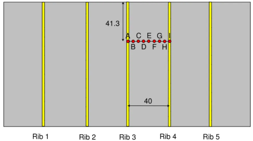
The Plexiglas plate-rib assembly used for velocity measurements was also used to evaluate the drive point mobility of a rib-stiffened plate. First, to be evaluated experimentally is the dependence of the drive point mobility on the location of excitation relative to the ribs. Figure 7 shows the configuration of the nine measurement points (labeled A through I) and the location of the five 235 mm deep ribs that stiffened the plate.
41.3 40 Rib 5 Rib 4 Rib 3 Rib 2 Rib 1 E A I B H C G D F
Figure 7: Sketch showing the periodic structure used to evaluate the model. All dimensions are given in centimetres.
The mobility at each of the nine points was measured in turn using a Wilcoxon F4 integrated shaker and impedance head. The force was applied via small indenter (6.6 mm diameter) to approximate the assumption of an infinitely small indenter implicit in the semi-modal finite plate approach which is based on thin plate theory. Estimates were corrected for the effect of the mass below force gauge (which is dominated by the mass of the mounting screw). This paper only considers the real part of the mobility because this is the component associated with power injection, and agreement between measured and predicted results were similar for both real and imaginary parts.
Figure 8 shows that the real part of the drive point mobility is a function of location. It is important to note that there are four measurement pairs (A&I, B&H, C&G, and D&F) which are symmetric about position E and have nominally identical distances (0, 5, 10, and 15 cm) to the nearest adjacent rib. There is no such symmetry and common distance to the perimeter of the ribbed-plate. 100 1000 1E-5 1E-4 1E-3 0.01 R e a l Pa rt o f M o bi lity , [ m /N s ] Frequency, [Hz] Thin Plate Thin Beam On Rib 3 (A) 5 cm (B) 10 cm (C) 15 cm (D) 20 cm (E) 15 cm (F) 10 cm (G) 5 cm (H) On Rib 2 (I) Measured 0.1 1 0.1 1 Meas ure d Mobi lity / Infin ite Pl ate Mob ili ty , [-]
Source Distance / Bending Wavlength, [-] 5 cm 10 cm 15 cm 20 cm 25 cm
Figure 8: Measured real part of the drive point mobility as a function of distance from a 235mm deep rib. Shown for comparison are estimates for infinite plates and beams of the same thickness from thin plate theory.
Figure 9: Normalised mobility as a function of the non-dimensional distance between the drive point and the
235mm deep rib.
There are three important observations to be made.
• The measured mobility is very similar for positions that have a nominally identical distance to an adjacent rib. Thus it is the distance to an adjacent rib that is most important in determining the mobility – the distance to the edge of the plate perpendicular to the ribs is of much less importance.
• For points near the center of the bay (Points D, E, & F, more than 15 cm from a rib), the mobility is reasonably approximated by that of an uncoupled infinite plate of the same thickness.
• As the distance to an adjacent rib decreases so does the mobility. For locations immediately above a rib (positions A and I) the measured mobility is reasonably approximated, below about 1000 Hz, by the mobility of an uncoupled infinitely long beam of the same depth and width as the rib. Above about 1000 Hz, the measured mobility increases with increasing frequency, and as suggested by the trend of the mobility for a point 5 cm away, will tend to the mobility of a an uncoupled infinite plate at high enough frequencies.
To examine the importance of source position relative to a stiffening rib the mobilities of Figure 8 were normalized by that of an infinite plate, and plotted as a function of the source distance normalized by the bending wavelength. The results are shown in Figure 9. There are two very important observations. First, when the ratio of the source distance to bending wavelength is greater than unity the plate can be considered as an infinite uncoupled plate because the ribs have minimal effect. Second, when this ratio is less than one-quarter (0.25) the
ribs play prominently and the mobility is considerably less than that of an uncoupled infinite plate. This had been observed by Lin and Pan [10] from theoretical calculations. For small enough values the mobility, as shown by Figure 8, will tend to that of a rib. For ratios between ratios 0.25 and 1.0, the normalized mobility will oscillate about unity (first greater than that of the infinite plate and then less, and so on) as it converges to unity. Measurement of bending wavenumbers on a wood joist floor [11] also suggest when the distance to joist was more than one-quarter bending wavelength the joists had little effect on the wavenumber measured parallel to the joists.
The measured results shown in Figure 8 and Figure 9 indicate that the mobility of a rib-stiffened plate cannot be adequately described by the two limits – infinite plate and infinite beam. The semi-modal finite plate approach is now evaluated as a method to predict the mobility of complex rib-stiffened structure shown in Figure 7. Because distance to the nearest adjacent rib is considerably more important in determining the mobility than the distance to the edge of the plate, the following figures show the average mobility for position pairs having nominally identical distances to a rib.
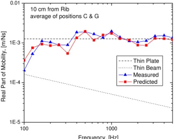
Figure 10 and Figure 11 show the semi-modal finite plate approach correctly predicts the magnitude and the trends of the mobility when the drive point is 20 and 10 cm from a rib, respectively. 100 1000 1E-5 1E-4 1E-3 0.01 R e a l Pa rt o f Mo b ili ty, [m/N s] Frequency, [Hz] Thin Plate Thin Beam Measured Predicted 20 cm from Rib position E 100 1000 1E-5 1E-4 1E-3 0.01 R e a l Pa rt o f Mo b ili ty, [m/N s] Frequency, [Hz] Thin Plate Thin Beam Measured Predicted 10 cm from Rib
average of positions C & G
Figure 10: Measured and predicted real part of the drive point mobility for a source (at position E) 20 cm from a 235mm deep rib. Shown for comparison are estimates for infinite plates and beams of the same thickness from
thin plate theory.
Figure 11: Measured and predicted real part of the drive point mobility for a source (at position C, or G) 10 cm
from a 235mm deep rib. Shown for comparison are estimates for infinite plates and beams of the same
thickness from thin plate theory.
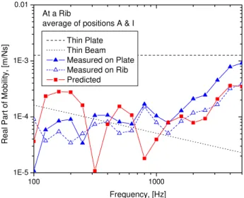
Results for the case with the drive point 5 cm from the rib, Figure 12, also show good agreement between measurement and prediction. Figure 13 shows the mobility measured when the plate is excited immediately above a rib, and when the rib is excited directly from below on the free edge. The measured mobility for the two cases is similar below about 1000 Hz, suggesting that at these frequencies the plate and rib are well connected. Above 1000 Hz the mobility measured above the rib on the plate is higher than that measured directly on the bottom of the rib, suggesting that the bolted connection between the plate and rib may not be adequate to ensure no relative motion along the surface of contact. Comparing these two measured mobilities with the predicted for a drive point on the plate directly above the rib, one can see that above
about 1000 Hz the prediction agrees quite well with the measurement made directly on the rib. This further supports the idea that there may have been relative motion at the plate rib junction in this frequency range. Below 1000 Hz the prediction is not good, particularly because the prediction exhibits significant dips in the mobility at 315 and 800 Hz which are not present in either set of measurements.
100 1000 1E-5 1E-4 1E-3 0.01 R e a l Pa rt o f Mo b ili ty, [m/N s] Frequency, [Hz] Thin Plate Thin Beam Measured Predicted 5 cm from Rib
average of positions B & H
100 1000 1E-5 1E-4 1E-3 0.01 R e a l Pa rt o f Mo b ili ty, [m/N s] Frequency, [Hz] Thin Plate Thin Beam Measured on Plate Measured on Rib Predicted At a Rib
average of positions A & I
Figure 12: Measured and predicted real part of the drive point mobility for a source (at position D, or H) 5 cm
from a 235mm deep rib. Shown for comparison are estimates for infinite plates and beams of the same
thickness from thin plate theory.
Figure 13: Measured and predicted real part of the drive point mobility for a source (at position A, or I) directly
above a 235mm deep rib. Shown for comparison are estimates for infinite plates and beams of the same
thickness from thin plate theory.
Reviewing all predictions it is evident that all predictions exhibit a dip in either the 315 or 400 Hz third-octave band and this dip is typically not present in the measurements. This needs further examination, but it is suggested that differences in the boundary conditions of the rib (assumed simply supported by the model, but measurement conditions were closer to free) are the cause. Effect of differences in the measured and predicted modal response of the rib will have the greatest effect on the accuracy of the drive point mobility when the point is located immediately above a rib, because measurements suggest for this position the mobility will be dominated by the rib.
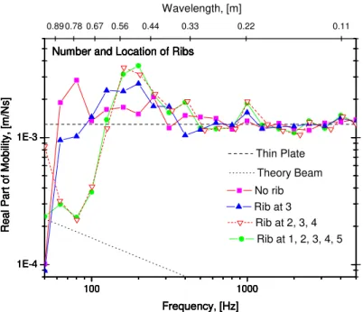
Figure 14 shows the measured drive point mobility at position E for varying number and location of 235 mm ribs. Comparing the mobility for the plate without a rib and when a rib is installed at position 3 (20 cm from drive point), one can see that there is a pronounced effect below about 250 Hz, but above this frequency there is much less. At 250 Hz, the ratio of distance to bending wavelength is about 0.5. Adding ribs at positions 2 and 4 (60 and 20 cm from the drive point, respectively) cause a significant change in the mobility below about 160 Hz. At 160 Hz, the ratio of source distance to bending wavelength is about to 0.4 for the closest added rib and about 1.0 for the farthest added rib. However, adding two more ribs at positions 1 and 5 (100 and 60 cm from the drive point, respectively, has very little effect except in the 50 Hz band.
100 1000 1E-4 1E-3 100 1000 1E-4 1E-3 100 1000 1E-4 1E-3 100 1000 1E-4 1E-3 100 1000 1E-4 1E-3 0.11 0.22 0.33 0.44 0.56 0.67 0.78 0.89 R e a l Part of Mobi lit y , [m/N s] Frequency, [Hz] Rib at 1, 2, 3, 4, 5 Number and Location of Ribs
R e a l Part of Mobi lit y , [m/N s] Frequency, [Hz] Thin Plate Number and Location of Ribs
R e a l Part of Mobi lit y , [m/N s] Frequency, [Hz] Theory Beam Number and Location of Ribs
R e a l Part of Mobi lit y , [m/N s] Frequency, [Hz] No rib Number and Location of Ribs
R e a l Part of Mobi lit y , [m/N s] Frequency, [Hz] Rib at 3 Number and Location of Ribs
Wavelength, [m]
Rib at 2, 3, 4 Number and Location of Ribs
Figure 14: Measured real part of the drive point mobility as a function of the number and location of the ribs. Shown for comparison are estimates for infinite plates and beams of the same thickness from thin plate theory.
As was observed by moving the drive point closer to a rib, the effect of the ribs is a function of the bending wavelength. There seems to be minimal effect due to removing or replacing a rib when the distance from the drive point is greater than about one-half bending wavelength.
6 DISCUSSION AND CONCLUSIONS
This paper has presented a prediction model that uses finite plates with a semi-modal approach to predict a periodic structure where the ribs needed not be perfectly periodic (i.e., spaced a uniform distance apart). The model is shown to predict the velocity and mobility of a homogeneous and isotropic periodic structure with good accuracy in most cases.
Measured and predicted results showed that very high velocity level difference (VLD) can be obtained in rib-stiffened structures and that in general there is more attenuation at the first junction than at subsequent junctions. This is because transmission from bending to bending is weak at each junction while there is significant wave conversion from in-plane to bending due to the eccentric nature of the junctions. Consequently, a model that assumes pure bending will significantly overestimate the VLD when the source and receive bays are separated by several junctions.
Measured results showed that the mobility of an uncoupled plate or beam provide reasonable upper and lower bounds on drive point mobility. The actual value is a function of the bending wavelength and the distance from the drive point to the nearest rib. Both measurements and predictions showed that if the ratio of the distance to the bending wavelength was less than 0.25 the rib would significantly lower the mobility. For ratios greater than 0.25 the mobility would be controlled by that of the plate and, for practical purposes, the mobility could be approximated by that of an uncoupled infinite plate of the same thickness. Similarly, the effect of adding or removing a rib from the plate was dependent on the distance to the drive point. However, because adding or removing a rib changes the modal response of the plate the sensitivity to source position appeared to be somewhat greater.
The measured and predicted results confirm that to adequately predict the power injected by one or more point forces and the resulting distribution of vibration energy in a rib-stiffened structure it is necessary to use a modeling approach that explicitly considers multiple arbitrarily located ribs. The approach presented here is one such example.
7 REFERENCES
[1] Jonas Brunskog, 2005, “A wave approach to structural transmission in periodic structures: Thin beam case,” Acta Acustica, Vol.91, pp. 91-102.
[2] Y.K. Tso and C.H. Hansen, 1998, “The transmission of vibration through a coupled periodic structure,” Journal of Sound and Vibration, Vol. 215(1), 63-79.
[3] E. Rébillard and J.-L. Guyader, 1995, “Vibrational behaviour of a population of coupled plates: hypersensitivity to the connexion angle”, Journal of Sound and Vibration, 188(3), 435-454.
[4] I. Bosmans 1998 Analytical Modelling of Structure-Borne Sound Transmission and Modal Interaction at Complex Plate Junctions. PhD Dissertation, KU Leuven, Belgium.
[5] I. Bosmans, T.R.T. Nightingale, 2001,“Modeling vibrational energy transmission at bolted junctions between a plate and a stiffening rib," Journal of the Acoustical Society of
America, Vol. 109(3), pp. 999-1010
[6] S. Schoenwald, T.R.T. Nightingale, 2000, "Measurement of structural intensity on plate structures," Canadian Acoustics, Vol. 29(3), September, Proceedings Issue of Canadian Acoustics, pp. 102-103.
[7] B.M. Gibbs and Y. Shen, 1987, “The predicted and measured bending vibration of an L-combination of rectangular thin plates,” Journal of Sound and Vibration, Vol. 112(3), pp. 469-485.
[8] T. R. T. Nightingale, R. E. Halliwell, J. D. Quirt, 2002, “Effectiveness of toppings to control flanking transmission in lightweight constructions”, Proceedings of Forum Acusticum, Sevilla 2002, RBA-CIB-009-IP, pp. 1-6.
[9] T. R. T. Nightingale, I. Bosmans, 2005, “On the distribution of transverse vibration in a periodic rib stiffened plate,” Proceedings of Forum Acousticum 2005.
[10] Tian Ran Lin, Jie Pan, 2006, “A closed form solution for the dynamic response of finite ribbed plates,” J. Acoust. Soc. Am. Vol. 119 (2), pp. 917-925.
[11] T.R.T Nightingale, R.E. Halliwell, G. Pernica, 2004, “Estimating in-situ material properties of a wood joist floor: Part 1 – Measurements of the real part of the bending wavenumber,” Journal of Building Acoustics, Vol. 11 (3), pp. 175-196.