ATLAS:
A Framework for Large Scale
Automated Mapping and Localization
by
Michael Carsten Bosse
Submitted to the Department of Electrical Engineering
and Computer Science
in partial fulfillment of the requirements for the degree of
Doctor of Philosophy in
Computer
Science and EngineeringMAssACHUSET 'ING
at the OF TECHNOLOG
MASSACHUSETTS INSTITUTE OF TECHNOLOGY
APR 15 2004
Feb 2004
LIBRARIES
@Massachusetts
Institute of Technology 2004. All rights reserved.Author ...
Department of Electrical Engineering
and Computer Science
Feb 2, 2004
C ertified by
...
Seth Teller
Associate Professor
Thesis Supervisor
C ertified by ...
John J. Leonard
Associate Professor
Th.i's Supcrvisor
Accepted by...
Arthur C. Smith
Chairman, Department Committee on Graduate Students
ATLAS:
A Framework for Large Scale
Automated Mapping and Localization
by
Michael Carsten Bosse
Submitted to the Department of Electrical Engineering and Computer Science
on Feb 2, 2004, in partial fulfillment of the requirements for the degree of
Doctor of Philosophy in Computer Science and Engineering
Abstract
This thesis describes a scalable robotic navigation system that builds a map of the robot's environment on the fly. This problem is also known as Simultaneous Local-ization and Mapping (SLAM). The SLAM problem has as inputs the control of the robot's motion and sensor measurements to features in the environment. The de-sired output is the path traversed by the robot (localization) and a representation of the sensed environment (mapping). The principal contribution of this thesis is the introduction of a framework, termed Atlas, that alleviates the computational restric-tions of previous approaches to SLAM when mapping extended environments. The
Atlas framework partitions the SLAM problem into a graph of submaps, each with
its own coordinate system. Furthermore, the framework facilitates the modularity of sensors, map representations, and local navigation algorithms by encapsulating the implementation specific algorithms into an abstracted module. The challenge of loop closing is handled with a module that matches submaps and a verification procedure that trades latency in loop closing with a lower chance of incorrect loop detections inherent with symmetric environments. The framework is demonstrated with several datasets that map large indoor and urban outdoor environments using a variety of sensors: a laser scanner, sonar rangers, and omni-directional video.
Thesis Supervisor: Seth Teller Title: Associate Professor
Thesis Supervisor: John J. Leonard Title: Associate Professor
Acknowledgments
First of all, I would like to thank my family, Steffi, Erika, and Carsten for their ongoing support and encouragement;
I want to thank my advisors, Seth and John, for all the emergency meetings,
advice, and for going easier on me at the end; My thesis committee, Eric and Leslie, for their invaluable comments on the early drafts; Paul, the best person I have ever worked with, for bringing out my productive side; Larry, for his writing tutelage and letting me crash at his place during the most difficult weeks of the writing; Elise's mother, for counseling me with regards to my writers' block; My friends, Erik, Chris and Matt, for brainstorming with me and letting me bounce so many ideas off of them; Jill and Bryt, for taking care of all the administrative details that had me running in circles;
And most of all, I thank my beloved, Elise, for standing by me even when I was at my most abject, for reading, organizing, and giving input on a topic she knows little about, and for her love.
Contents
1 Introduction
1.1 The Simultaneous Localization and Mapping Problem 1.2 C hallenges . . . .
1.3 Related Research . . . .
1.4 Atlas Fundamentals and System Overview . . . . 1.5 Working Hypothesis and Contributions . . . . 1.6 R oad M ap . . . . 2 Atlas Framework 2.1 Introduction . . . . 2.2 2.3 2.4 2.1.1 Basic Principles . . . . 2.1.2 Loop Closing and Uncertainty
Atlas Components . . . . 2.2.1 Uncertainty Projection . . . 2.2.2 Genesis . . . .
2.2.3 Map-Matching . . . .
2.2.4 Cycle Verification . . . .
2.2.5 Traversal with Competing Hy
Atlas Modules . . . .
2.3.1 Local SLAM . . . .
2.3.2 Map-Matching . . . .
Global Map Frame Optimization . .
otheses
2.5 Summary and Running Time Analysis
19 19 21 25 28 31 32 33 . . . 33 33 34 37 37 40 41 42 45 48 51 51 52 53
3 Atlas with 2D Laser Lines 3.1 Introduction ...
3.2 Line Feature Estimation . . . .
3.2.1 Line Splitting and Fitting . . . . .
3.3 Landmark Kalman Filter . . . .
3.3.1 Odometry Model . . . .
3.3.2 Advanced Odometry Model . . . .
3.3.3 Measurement Models and Processing
3.3.4 Robot Relocalization . . . .
3.4 Map Matching . . . . 3.4.1 Line Signature Strings . . . .
3.4.2 Repetitive Structure . . . .
3.4.3 Alignment Optimization . . . .
3.4.4 Summary . . . . 3.5 Experimental Results . . . .
3.5.1 MIT's Killian Court . . . .
Summary
3.5.2 Ten loops in a small-scale environment . . . .
4 Atlas with Wide Angle Sonar
4.1 Introduction . . . . 4.2 Sonar Features . . . . 4.2.1 Point Features . . . . 4.2.2 Line Features . . . .
4.3 RANSAC Data Association . . . .
4.3.1 Adjacency preprocessing . . . .
4.4 Multiple Vantage-Point Kalman Filter . . . . 4.4.1 Saved robot poses . . . . 4.4.2 Feature updates . . . . 4.4.3 Feature Initialization . . . . 4.4.4 Performance Metric . . . . 55 55 57 60 62 62 65 67 77 79 80 81 81 83 84 85 96 101 101 102 102 104 104 105 108 108 110 112 113
4.5 Map Matching and Signatures . . . .
4.6 Experimental Results: Killian Court
5 Atlas with 2D Laser Scan-matching
5.1 Introduction . . . .
5.2 Iterative Closest Point Scan-matching
5.2.1 Normals . . . .
5.2.2 Transformation Update
5.3 Pose Snapshot Kalman Filter
5.3.1 Relocalization . . . . . 5.3.2 Performance Metric . . 5.4 Map Matching . . . . 5.5 Experimental Results . . . . . 5.5.1 Killian Court . . . . . 5.5.2 Ten Loops . . . . 5.5.3 Victoria Park . . . . .
5.5.4 Pennsylvania Coal Mine
6 Atlas with Omnidirectional Video
6.1 Introduction . . . .
6.1.1 Atlas requirements . . . .
6.1.2 Assumptions . . . .
6.2 Relationship to Previous Work . .
6.2.1 Feature Geometry . . . . .
6.2.2 Chapter Summary . . . . .
6.3 Single View Geometry . . . .
6.3.1 Omnicam projection model
6.3.2 Image Points . . . . 6.3.3 Image Lines . . . . 6.3.4 Vanishing Points . . . . . 6.3.5 Line estimation . . . . . . . . . . . . 145 145 146 147 148 149 150 150 151 152 153 154 155 113 115 119 119 120 120 122 127 129 129 130 131 131 132 137 . . . . 141
6.3.6 RANSAC for Vanishing Points . . . .
6.3.7 Expectation Maximization for Vanishing Points
6.4 Multiple View Geometry . . .
6.4.1 Point Triangulation 6.4.2 Line Triangulation 6.4.3 Line Segment Matching 6.4.4 Bundle Adjustment . .
6.5 Local Mapping Data flow . . .
6.5.1 Preprocessing . . . . . 6.5.2 Feature Tracking . . . 6.5.3 Bundle Adjustment . . 6.6 Map Matching . . . . 6.7 Experimental Results . . . . . 6.7.1 Hardware Setup . . . . 6.7.2 Lounge Sequence . . . . 6.7.3 Library Sequence . . . . 6.7.4 Atrium Sequence . . . .
with Dynamic Programming
156 . . . . 158 . . . . 160 . . . . 160 . . . . 161 . . . . 162 . . . . 163 . . . . 166 . . . . 166 . . . . 168 . . . . 168 . . . . 169 . . . . 170 . . . . 170 . . . . 171 . . . . 172 . . . . 173
6.7.5 Tech Square with Omnibike . . . . 186
7 Conclusion 7.1 Sum m ary . . . . 7.1.1 Implementation Comparison . . . . 7.1.2 Connectivity Metric . . . . 7.2 Failure m odes . . . . 7.3 Future Work . . . .
7.3.1 Relocation with partial observability . . .
7.3.2 On-line map fusion . . . .
7.3.3 Global state estimation . . . .
7.3.4 Improved implementation of Atlas modules
7.3.5 Multi-robot Mapping . . . . 191 191 192 193 196 199 199 200 200 201 202
List of Figures
1-1 A graph of map-frames . . . . 2-1 2-2 2-3 2-4 2-5 2-6 2-7 2-8 3-1 3-2 3-3 3-4 3-5 3-6 3-7 3-8 3-9 3-10 3-11 3-12 3-13 Ambiguity condition . . . . The Dijkstra Projection using two different Dijkstra Shortest Path Tree . . . . Cycle Verification . . . . Hypothesis state transition diagram . . . .The spatial and topological evolution of an The spatial and topological evolution of an Algorithm Summary . . . .
Typical Laser Scan . . . . Line Parameterization . . . .
Line Splitting . . . .
source nodes. . . . .
. . . .
Atlas graph, Part
Atlas graph, Part
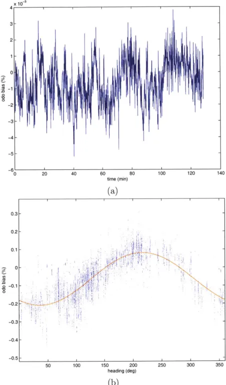
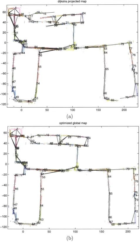
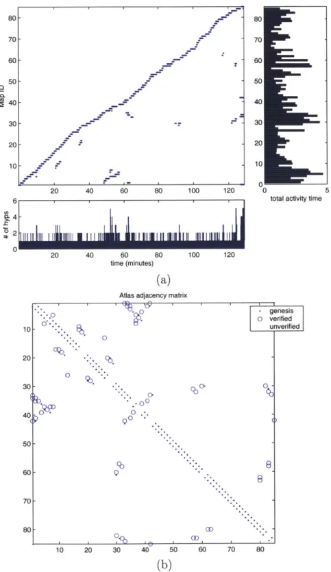
Seeding the robot position for a juvenile hypothesis . . Line Signature Elements . . . . Map-Matching as a search for a transformation between Killian Court topology . . . . Killian laser maps using uncorrected odometry . . . . . Uncorrected odometry bias . . . . Odometry trajectories . . . . Killian laser m aps . . . . Killian laser adjacency matrix . . . . Killian laser Kalman filter residuals . . . .
maps 29 36 38 40 44 48 49 50 54 I . II 56 58 61 78 81 84 88 89 90 91 . . . 92 . . . 93 . . . 94
3-14 Killian global optimization residuals . .9 Killian laser processor load . . . . Building 6 and odometry path . . . . . Tenloops laser maps . . . . Tenloops adjacency and map times . . Tenloops laser Kalman filter residuals Tenloops global optimization residuals
. . . . 95 . . . . 97 . . . . 98 . . . . 99 . . . . 100 . . . . 100 3-15 3-16 3-17 3-18 3-19 3-20 4-1 4-2 4-3 4-4 4-5 4-6 4-7 5-1 5-2 5-3 5-4 5-5 5-6 5-7 5-8 5-9 5-10 5-11 5-12 5-13 5-14 5-15 Sonar Features ... . ... . . . . .. . . . . 103
Sonar Point Matching . . . . 107
Sonar Line Matching . . . . 107
Killian sonar maps . . . . 116
Killian sonar adjacency matrix . . . . 117
Killian sonar Kalman filter residuals . . . 118
Killian global optimization residuals . . . . 118
Iterative Closest Point . . . . 121
Scan point normal . . . . 122
Scan-match Diagram . . . . 128
Killian scan-match optimized map . . . . 132
Killian scan-match adjacency and map times . . . . 133
Killian scan-match Kalman filter residuals . . . . 134
Killian global optimization residuals . . . . 134
Ten loops scan-match optimized map . . . . 135
Ten loops adjacency and map times . . . . 136
Victoria Park scan-match map . . . . 138
Victoria Park adjacency and map times . . . . 139
Victoria Park scan-match Kalman filter residuals . . . . 140
Victoria Park global optimization residuals . . . . 140
Mines scan-match optimized map . . . . 141
Mines scan-match processing time . . . . 142 94
5-16 Mines scan-match adjacency and map times
5-17 Mines scan-match Kalman filter residuals . . . . 144
5-18 Mines global optimization residuals . . . . 144
6-1 Omnicam Geometry . . . . 152
6-2 Projection of a 3-D line . . . . 157
6-3 Line ordering . . . . 163
6-4 Data Flow Diagram . . . . 166
6-5 Omnicam Hardware . . . . 171
6-6 Omnicam sample image . . . . 172
6-7 Lounge residual point errors . . . . 174
6-8 Lounge residual line errors . . . . 174
6-9 Lounge map match scores . . . . 175
6-10 Lounge plan view . . . . 176
6-11 Lounge oblique view . . . . 176
6-12 Lounge plan view of path . . . . 177
6-13 Lounge oblique view of path . . . . 177
6-14 Library residual errors . . . . 178
6-15 Library map match scores . . . . 179
6-16 Library plan view . . . . 180
6-17 Library oblique view . . . . 180
6-18 Library plan view of path . . . . 181
6-19 Library oblique view of path . . . . 181
6-20 Atrium reprojection errors . . . . 182
6-21 Atrium map match scores . . . . 183
6-22 Atrium plan view . . . 184
6-23 Atrium oblique view . . . 184
6-24 Atriun plan view of path . . . . 185
6-25 Atrium profile view of path . . . . 185
6-26 Camera mounted on bicycle . . . . 186
6-27 6-28 6-29 6-30 6-31 6-32 6-33 7-1 7-2 7-3
Omnibike residual point errors . . . .
Omnibike residual line errors . . . . . Omnibike map match scores . . . . . Omnibike oblique view . . . . Omnibike overlay plan view . . . . . Omnibike plan view . . . . Omnibike oblique path view . . . . .
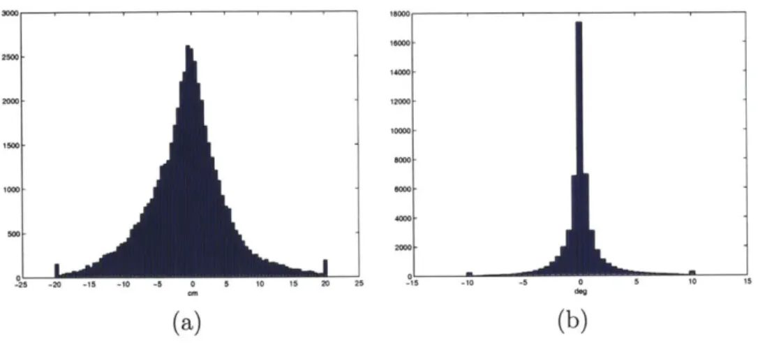
Killian Court robot pose comparison Pose Errors . . . .
Time Adjacency Matrix . . . .
. . . . 187 . . . . 187 . . . . 188 . . . . 189 . . . . 189 . . . . 190 . . . . 190 194 195 197
List of Tables
1.1 Related Research . . . . 26
2.1 Atlas hypothesis types . . . . 47
4.1 Map signature elements definitions . . . . 113
6.1 Image sequences for experiments. . . . . 171
7.1 Standard deviation of global robot pose errors. . . . . 193
Chapter 1
Introduction
The problem of simultaneous localization and mapping (SLAM) is to enable a mobile robot to build a map of its environment, while simultaneously using this map to navigate. This thesis addresses two key shortcomings of previous SLAM algorithms: scale and modularity. It demonstrates a SLAM algorithm that can cope with large-scale, cyclic environments, and a single, unified SLAM architecture that has been successfully applied to a variety of different input sequences, including laser, sonar, and omnidirectional video data.
1.1
The Simultaneous Localization and Mapping
Problem
The Global Positioning System (GPS) has revolutionized localization. Developed in the 1970s and 80s, GPS provides the user with an earth relative position and velocity estimate to sub-meter accuracy under certain conditions. However, knowing one's location in an arbitrary coordinate system has little value without a map that links these coordinates to a representation of the environment.
Together, a localization system and maps allow individuals to navigate success-fully. Nevertheless, there are limitations to the efficacy of the integration of maps and localization. OPS functions fully only in outdoor locations with good visibility
to satellites. It is not practical for use indoors, underground, underwater, in urban canyons, or on planets lacking GPS satellites. Maps are highly dependent on in-tensive human labor for their construction and are limited by the models used to represent the features of the environment on any given map. Thus, while localization and mapping are basic aspects of successful navigation, their effective integration and application remains a significant challenge in many areas.
In mobile robotics, localization and mapping are fundamental requirements for applications such as exploration, path planning, and dynamic object tracking. In order to effectively accomplish tasks in which they interact with their environments, robots need to know where they are. However, this knowledge of position is meaning-less without a map that relates the robot's location to its environment. Autonomous vacuum cleaners, supermarket floor washers, and tour guide robots [7] are examples of existing mobile robots that navigate based upon maps.
These maps can be provided to the robot ahead of time or simultaneously gener-ated by the robot while localizing. This latter form of mapping is both more desirable and more challenging. A priori maps often do not exist or are incomplete, inaccurate, or inadequate for a robot's needs, while robots with the ability to self-generate maps are able to explore previously unmapped areas. Furthermore, an internally generated map will generally be more up-to-date than one previously produced. The challenge ensues when a robot must localize concurrently with mapping. Individually, mapping and localization are straightforward tasks accomplished with bounded complexity. When coupled, the complexity growth of these tasks can escalate in an unbounded manner. Overcoming this hurdle is a key to expanding the future of mobile robotics. In the robotics community, the task of a robot building a map and simultaneously localizing from it is commonly referred to as Simultaneous Localization and Mapping
(SLAM). Most current SLAM implementations are limited by the size and type of
the environments they can handle. There are few existing algorithms that work well in large-scale environments; however, there are several notable active projects that seek to tackle large-scale mapping, including the mapping of abandoned coal mines
[55],
searching the ocean for explosive mines [43, 33], and capturing models ofentire cities [52].
This thesis approaches large-scale SLAM from a different perspective. Rather than develop a system in which all components are tightly integrated and therefore dependent upon each other, it is possible to separate the dependencies into modules. This method of operation allows for flexibility and variety in implementing SLAM so-lutions. This thesis proposes a system for encapsulating existing SLAM solutions for small-scale environments within a framework that allows them to be applied to large-scale SLAM problems. This modular framework also precludes a dependence upon a single choice for sensor or map representation, further facilitating the implementa-tion of different SLAM systems. To accomplish this, each of the major challenges to achieving real-time SLAM must be addressed.
1.2
Challenges
The challenges to achieving successful SLAM are varied and often interconnected. Sensor, model, and mapping variety have lead to a hodgepodge of methods for ap-proaching SLAM. The need to map large-scale environments complicates SLAM and further exacerbates issues such as coupled uncertainty, loop closing, and loop valida-tion. An effective large-scale SLAM framework must address these challenges.
Model variety makes SLAM more difficult. Differences in sensor measurement, robot dynamics, and map representation models convolute efforts to implement a unified and systematic approach to SLAM. Two basic classes of sensors, propriocep-tive and mapping, are utilized in SLAM. Proprioceppropriocep-tive sensors directly measure a robot's relative motion using gyroscopes, accelerometers, wheel odometers, and steer angle sensors. Robots like ground rovers and water surface crafts move only in 2D with rotations. Robots with 6 degrees of freedom (DOF) of motion capabilities, such as aircraft, helicopters, underwater vehicles, and hand-held cameras, can access more environments. Because proprioceptive sensors measure only relative motion of the robot, they lead to unbounded growth in localization error.
They can be used to correct the unbounded dead-reckoning errors of proprioceptive sensors by re-observing previously mapped features. These mapping sensors may be active or passive and measure bearing, range, or both. For example, a camera is a passive, bearing-only sensor, whereas a sonar ranger is an active, range-only sensor. The most useful sensors measure both range and bearing. A common example of a fully observable sensor is a laser scanner, which can measure all of the modeled degrees of freedom of an environment features from a single pose. However, sensors that observe only partial DOF of the environment's features require that multiple measurements from different positions be combined in order to obtain a complete view of structure in the scene. With mapping sensors it is necessary to interpret the data correctly, which means having an appropriate model for observations of features in the environment.
A final form of model variety inherent within SLAM is map representation. The
environment and the set of available sensors determine the choice of map representa-tion. Feature-based maps [47] work best in structured or sparse environments in two or three dimensions. Evidence grids [40, 46] are most effective in small unstructured
2D environments, particularly when using fully observable sensors [12].
Each particular implementation of SLAM will have its own criteria for determin-ing which models will be used. These criteria must take into account the types of sensors available and environment to be mapped. Given that the process of mapping environments with robots is not deterministic, uncertainties exist in all of the models described above. These uncertainties themselves must be modeled with probabilities and reasonable assumptions must be made on the chosen error distributions. If errors in sensor measurements, robot dynamics and map fidelity are kept small, then it is possible to use a Gaussian noise assumption with linearized models. Unfortunately, in the real world, models are nonlinear and errors are often large or not Gaussian. Although Gaussian distributions can be fit to nonlinear models when the errors are small, the linearizations are no longer accurate when these errors become large. Non-Gaussian errors include multi-modal errors that occur, for example, from mistakes in matching during data association.
Another major challenge in SLAM arises from the coupling of sensor and robot uncertainties. Coupling occurs when noisy sensor measurements are taken from un-certain robot poses. This coupling is most apparent between two mapped features.
If there were no uncertainty in the robot pose when mapping the features, then the
errors of the features would be independent from one another. However, since both features are mapped from the same uncertain robot, their errors are linked. For ex-ample when the robot makes a subsequent measurement on one feature, it improves the knowledge of the robot's pose and hence consequently improves also the posi-tion of the second feature. This coupling is represented, when using Gaussian error distributions, as non-zero off-diagonal covariance matrix elements which cannot be ignored.
Large scale environments exacerbate the obstacles to SLAM by increasing the computational requirements. Often SLAM algorithms do not have constant time complexity per update. (Other constant time SLAM algorithms exist; however, they either don't close loops
[39]
or make global linearization assumptions [56]) As new parts of the environment are mapped, their errors are coupled through the uncertain robot position to the errors of all the other mapped parts. Subsequently, when re-observing old parts of the map, all the coupled parts of the map will also need to be updated. Thus the computation required to process each measurement increases as the size of the map increases, unless some steps are taken to limit the coupling.As noted above, the map elements and the robot poses are statistically coupled, and even in the simple Gaussian case, all the cross-covariances need to be maintained. (The cross-covariances are significant even if the features are not co-visible). Since the estimated errors of all the map elements are correlated, processing each sensor measurement results in at least a quadratic growth in memory and computation as the size of the map increases. The challenge is to develop valid approximations such that not all correlations among robot and map elements need to be maintained. Ideally, the computational time should remain nearly constant per sensor measurement, and the memory required should grow nearly linearly with the size of the map.
close loops when revisiting previously mapped areas. The difficulty arises since the robot may take a long time and travel a significant distance before revisiting the area from which it started. Hence the open-loop uncertainty can be quite large and it will perhaps even be difficult for the robot to recognize that it is in a previously mapped region.
There are two algorithmic elements to loop closing. The first is data association, or, recognizing when a loop can be closed. The second element is incorporating the effects of a loop closure into the SLAM system state. The difficulty in data association is that the recognition of revisited areas in a particular environment is dependent upon both the growth of uncertainty in local mapping and the richness of the local map representation. A slower uncertainty growth enables the robot to traverse longer paths before a mismatch between two nearby ambiguous regions occurs. Additionally, richer maps are less likely to exhibit local symmetry and global ambiguity. The update of a loop closure event is also challenging, especially if the prior uncertainty is large. The update must be distributed in some manner around the loop if the map is to be expressed in a single coordinate system. The error accumulated around the loop is typically large and poorly modeled, therefore the process of distributing the residuals of the loop-closing constraint can lead to inconsistencies or tears in the map. Also, if all the map elements around an arbitrarily long loop must be updated, then the computational burden for processing sensor measurements can no longer be bounded
by a constant factor.
Loop closure validation is necessary to mitigate the errors associated with loop closing. There are two types of loop-closing errors: false positive matches and missed detected matches. False positive matches are situations in which the robot erroneously asserts that a loop has been closed; however, the inferred match is false. When the environment contains repetitive structure or local symmetries, the detected loop-closing map-matches may not be unique. Missed detections occur when a loop closure has been missed due to failure to successfully match the current map with a previously mapped area. Furthermore, the prior uncertainty of the robot before closing the loop may be too large to identify the correct match. Even when there is only one candidate
match, it is possible that the correct match has simply not been recognized yet and the lone existing match is incorrect. The challenge for the algorithm is to verify loop closure decisions before they are committed, to be certain that no mistakes are made.
1.3
Related Research
A review of related research reveals common issues in the field of SLAM. How various
methods address map and probabilistic representations, non-linearities, data associa-tion, scaling, and loop closing highlights the strengths and weaknesses of the different
methods. Table 1.3 summarizes the key references in terms of the aforementioned categories in a concise format. These previous research efforts will be referenced throughout the remainder of the thesis.
Probabilistic techniques have proven vital in attacking the large-scale simultane-ous localization and mapping problem. A variety of approaches have been proposed for representing the uncertainty inherent to sensor data and robot motion, including topological [30], particle filter [53, 39], and feature-based
[48]
models. Several success-ful SLAM approaches have been developed based on the combination of laser scan matching with Bayesian state estimation [27, 53]. All of these methods, however, encounter computational difficulties when closing large loops.The Kalman filter provides the optimal linear recursive solution to SLAM when certain assumptions hold, such as perfect data association, linear motion and mea-surement models, and Gaussian error models [48]. The convergence and scaling prop-erties of the Kalman filter solution to the linear Gaussian SLAM problem are now well-known (Dissanayake et al. [17]). Considerable recent research effort has been ex-tended toward mitigation of the 0(n2) complexity (where n is the number of features) of the Kalman filter SLAM solution. Efficient strategies for SLAM with feature-based representations and Gaussian representation of error include postponement [14], de-coupled stochastic mapping (DSM) [31], the compressed filter [26], sequential map joining [50], the constrained local submap filter [61], and sparse extended information filters (SEIFs) (Thrun et al. [56]; Thrun et al. [55]). Each of these methods employs
Researchers Map Rep. Nonlinear Data Association Scale
Coord. closing
Smith, Self, Cheesman [47] points EKF nearest no yes no
metric
Semantic Map [30] topological n/a n/a yes no no
semantic
yes
Gutmann & Konolige [27] laser scans full optim ICP except loops yes yes Sequential Map Joining [50] points & lines SP Map Joint Compatibility yes yes no
SEIFs [56] points EIF given yes yes no
FastSLAM [39] points particle filter given yes yes no
EKF
Sum of Gaussians [19] points Sum of bayesian no yes no
Gaussians
Choset's Voronoi [12] voronoi graph procedural n/a no yes yes
Postponement Filter [14] points EKF nearest no yes no
Compressed Filter [26] points EKF nearest yes yes no
Constrained Filter [61] points EKF nearest yes no yes
DSM [31] points EKF nearest yes yes no
Chong & Kleeman [11] points & lines EKF nearest yes no no
Atlas Laser Lines lines EKF nearest yes no yes
Atlas Sonar points & lines EKF nearest yes no yes
Atlas Scan-match scans EKF ICP yes no yes
Atlas Omni-video points & lines full optim nearest yes no yes 0d
a single, globally-referenced coordinate frame for state estimation. The Kalman filter can fail badly, however, in situations in which large angular errors and significant data association ambiguities invalidate the Gaussian error assumptions. The large-scale linearization inherent in methods that use a single, global coordinate system for error representation, such as SEIFs or DSM, will fail when closing large loops with unbounded linearization errors.
In outdoor and underground environments, several SLAM algorithms have been implemented for large scale datasets. Guivant and Nebot have published results for a dataset acquired in Victoria Park, Sydney, Australia, using the compressed filter [26], with an implementation that employs trees as "point" features. More recently,
Wang et ai. [60] and Hdhnel et al. [28] have achieved full 3D mapping of urban areas with dynamic objects using scan-matching. Thrun et al. [55] have demonstrated large-scale SLAM in a cyclic underground mine, also using scan-matching.
Some of the most successful experiments for autonomous loop closure in indoor environments have been performed by Gutmann and Konolige
[271.
One notable feature of their work is the use of a hybrid metrical/topological map representation:"A map is represented as an undirected graph: nodes are robot poses
with associated scans and links are constraints between poses obtained from dead-reckoning, scan-matching, or correlation. [27]"
One of the appealing aspects of a hybrid metrical/topological approach to mapping and localization [9, 30, 3, 12] is that uncertain state estimates need not to be referenced to a single global reference frame. The strategy of partitioning a large map into multiple smaller maps is intuitively appealing, both for its computational efficiency
and robustness. Chong and Kleeman [10] assert that ".. .. the local mapping strategy is devised ... to improve efficiency and to curb the accumulated 'inevitable errors'
from propagating to other local maps continuously." The hybrid metrical/topological approach models errors using Gaussian distributions only over local regions where linearization works well, rather than representing the entire environment with one
Gaussian distribution.
An alternative to the use of local linearization is the adoption of a fully nonlinear formulation of the SLAM problem, such as FastSLAM [39] or SLAM using a sum of Gaussians model
[19].
The computational requirements of these methods, however, remain poorly understood and uncharacterized in large cyclic environments. In future research, it may be possible to implement one of these techniques as the local mappingstrategy within the Atlas framework.
1.4
Atlas Fundamentals and System Overview
This thesis introduces a SLAM framework, termed Atlas, for the metaphor of a book with many adjacent maps. Atlas is a framework in which existing small-scale mapping algorithms are used to achieve real-time performance in large-scale, cyclic environ-ments. The approach does not maintain a single, global coordinate frame, but rather an interconnected set of local coordinate frames, analogous to atlas pages. The rep-resentation consists of a graph of multiple local maps of limited size. Each vertex in the graph represents a local coordinate frame (and a local map expressed with respect to that frame), and each edge represents the transformation between adjacent local coordinate frames. In each local coordinate frame, a map is built that captures the local environment and the current robot pose along with associated uncertainties. Together, the map and the coordinate frame within which it is defined are referred to as a map-frame. Figure 1-1 depicts a graph of map-frames in which two hypotheses maintain the robot position.
The spatial extent of each map is not predefined. Instead, Atlas limits the
com-plexity of each map. An intrinsic performance metric of the local SLAM processing
determines whether to transition to an existing adjacent map-frame or generate a new one. The map's complexity is easily bounded by placing a hard limit on the
b 1C / A
/
/
NFigure 1-1: A graph of three map-frames in which two maps (B and C) can express the current robot position (R).
maximum number of features that can be inserted into the map. The performance metric is based on the certainty of the current robot pose by measuring how well the current robot pose and map are consistent with the current sensor readings.
Atlas is a generic framework which incorporates a variety of techniques as the
local mapping module. The approach assumes that a suitable local SLAM algorithm exists that can produce consistent maps in small-scale (non-cyclic) regions with a fixed amount of computation for each new sensor observation. The local SLAM method may not incur an ever-growing computational burden, otherwise efficient global performance is not possible. For example with laser scan-matching, if local processing were based on the matching of a new sensor scan with all of the scans obtained in a local region, then local map complexity, which grows linearly with time, would not be bounded. Only a finite set of scans may be retained in any local
region to ensure that the local SLAM processing time can be bounded by a constant factor.
Each map's uncertainties are modeled with respect to its own local coordinate frame. The uncertainty of the edges (adjacency transformations) in the Atlas graph are represented by a Gaussian random variable and are derived from the output of the SLAM algorithm running in a local region. The framework limits the per-map computation by defining a measure of complexity for each map-frame, which is not allowed to exceed a threshold (the map capacity). Rather than operating on a single map of ever-increasing complexity, the Atlas framework simply switches its focus to a new or adjacent map-frame, when the current map frame grows too large or performs poorly.
The Atlas graph encompasses new edges to close cycles via an efficient map-matching algorithm. All the map representation based dependencies for map-matching two sub-maps are contained in an implementation specific module, the Map-Matching module, whereas the general framework indicates potential map matches for map-frames that fall within an approximate uncertainty bound of the current map. The framework computes these uncertainty bounds by integrating the coordinate trans-formations and associated error estimates along a path formed by the edges between adjacent map-frames. A background map projection process computes these paths and error bounds by using a variant of Dijkstra's shortest path algorithm [16].
The Atlas framework employs a verification step before integrating updates to the graph. The verification delays the acceptance of a map-match until additional map-matches are discovered that form a small consistent cycle in the graph. This procedure effectively increases the area of overlap considered to make sure that the map matches are not the result of ambiguous symmetries in the environment.
1.5
Working Hypothesis and Contributions
The Atlas framework abstracts and decouples the details of each sensor suite and environment characteristics from the mechanism for handling scale and loops. The
Atlas framework for large scale SLAM has been implemented for a variety of sensors
and tested in a variety of environments.
The first implementation uses extracted line features from a 2D scanning laser ranger on a B21 robot and models the environment as a collection of 2D line seg-ments. A second implementation utilizes line and point features measured by monau-ral ultra-sonic rangers. The third implementation again utilizes the laser ranger, but processes the raw laser data directly, using the technique of scan matching to relate data gathered from different positions without explicitly extracting any features from scans. A final implementation employs omni-directional video to model the environ-ment with vanishing directions, 3D lines, and 3D points. This impleenviron-mentation uses a 3D world model and batch optimization on each local map rather than a recursive navigation strategy.
These implementations have been tested in a variety of environments which can be categorized into three groups based on the type of robot and sensors employed. The first group (Sections 3.5, 4.6, 5.5) uses combinations of the laser and sonar sensors from a B21 robot traveling through the corridors of MIT's main campus. The second group (Section 6.7) also used the B21 robot, but mounted with an omnidirectional video camera. These data sets were also taken in and around MIT's campus, including the CSAIL Reading Room, the Building 200 Second Floor Lounge, the Atrium in the same building, and also along similar routes as Group One about the "Infinite
Corridor". Additionally, data sets from third party sources taken in Victoria Park, Sydney [41] and coal mines in Pennsylvania [55], (Section 5.5) were processed using the Scan-Match implementation.
address-ing of the Challenges described in Section 1.2. The issue of model variety is tackled through the modular framework where the details of the local SLAM module and Map-Matching module are abstracted from the general framework. Since the naviga-tion module need only work with a limited sub-map of the environment, it can employ non-scalable SLAM algorithms that fully address and model the coupled uncertainty among mapped features and the current pose. Similarly the sub-map approach can map large scale environments efficiently, since only a few submaps need to be ac-tive at any particular time. The Atlas framework allows constant time processing complexity under the condition that the open-loop uncertainty of the robot does not diverge. Atlas's Map-Matching module is employed to recognize loop closure events in large scale environments even when there are significant open loop errors. The
Atlas framework also validates detected loops before they are closed to address the
errors inherent in ambiguous environments.
1.6
Road Map
Chapter 2 will cover the details of the general Atlas framework whereas Chapters
3-6 cover details of specific implementations. The implementation using line features
extracted from a 2D laser scanner is described in Chapter 3. Chapter 4 covers the implementation using range measurements from sonar. Chapter 5 revisits the laser sensor, but processes the scans without extracting features by matching scans, and Chapter 6 presents the implementation for processing omnidirectional video. Chap-ter 7, the conclusion, compares the implementations, discusses failure modes, and presents future work.
Chapter 2
Atlas Framework
2.1
Introduction
The Atlas framework achieves SLAM through a modular approach. By providing flexible access to a variety of small-scale solutions, Atlas successfully accomplishes real-time, large-scale SLAM.
2.1.1
Basic Principles
The design of the Atlas framework rests on four basic principles: the elimination of a dependence on a global coordinate frame; the elimination of loop constraints; the elimination of predefined map extents, and the elimination of a dependence upon a
single lowlevel mapping sensor and navigation strategy.
The Atlas framework maintains no single, global coordinate frame, but rather, an interconnected set of local coordinate frames. Each frame contains a local map of limited extent, called a map-frame. Two coordinate frames are considered to be connected (adjacent) if their map-frames possess shared mapped structure. This adjacency is represented by a approximate coordinate transformation (ACT) between frames.
Local maps handle short sensor excursions; however, in an extended mapping task previously mapped regions will be revisited and loops need to be closed. After recog-nizing the closure of an extended loop, the composition of adjacency transformations is not constrained to be the identity transformation. This strategy is essential to achieving constant time performance in the Atlas framework since no global updates are required. (Nevertheless, the identity constraint can be applied off-line to refine the global arrangement of the multiple coordinate frames.)
The spatial extent of the map-frames is not predefined, but rather, determined by an intrinsic performance metric on the map-frame's associated map. Since the map complexity is bounded and the mapped features are in proximity to one another, the robot will exhibit a high performance metric when near the poses from which the features were mapped. The performance metric naturally drops when the robot is constrained from adding new features and leaves the proximity of mapped features, at which time the Atlas framework will invoke either a transition to an adjacent frame or the genesis of a new one.
The Atlas framework does not depend on a particular local navigation and map-ping strategy. Instead, local navigation and mapmap-ping are abstracted into a module that need only provide an estimate of the robot's current pose (along with its uncer-tainty) and a metric describing how well the current map explains the current sensor measurements. Likewise, the data association engine used to match maps is also modularized. By incorporating different sensor platforms and map representations, the modular design allows Atlas to scale a variety of SLAM implementations.
2.1.2 Loop Closing and Uncertainty
Loop closing is one of the most difficult issues in SLAM research. Two different types of errors can occur in loop closing: false positive matches and missed detected matches. The former refers to situations in which the robot, based upon a false
match, erroneously asserts that a loop is closed. The latter case occurs when a loop closure is missed due to failure to successfully match the current map with a previously mapped area. Atlas adopts a conservative loop closing and verification strategy which attempts to avoid false positive matches at the expense of increased loop closing latency and missing some genuine loop closure events. It is possible, however, to present an adversely designed environment with highly repetitive structure and a path in which the accumulated uncertainty is so large that the Atlas technique, as well as any known SLAM loop closing algorithm, will fail.
Given a particular environment, the difficulty of loop closure is dependent on the growth of uncertainty in the local SLAM method and on the richness of the local map representation. A smaller growth of uncertainty allows for longer paths to be followed before confusing two nearby ambiguous regions, and richer maps are less likely to be ambiguous. Additionally, an environment with less repetitive global structure will present fewer challenges to loop closing, since there will be fewer ambiguous regions. Uncertainty presents another challenge to SLAM. Local uncertainty results from noise introduced into individual measurements. Global uncertainty arises from the need to discern whether the region currently being observed by the robot consists of newly explored or previously visited territory. Both local and global uncertainty are exacerbated by repeated low-level features (e.g. periodic arrays of doors or windows) or high-level structure (e.g. nearby corridors that are nearly indistinguishable).
Uncertainty is a challenge to SLAM, because it is antagonistic both to achieving correctness and efficiency. When the mapping algorithm mistakes one local feature for another, or one region for another, it performs an incorrect data association and produces an incorrect map. On the other hand, if the algorithm expends excessive effort in an attempt to avoid such misassociations, it sacrifices efficiency. For algo-rithm designers, then, a key challenge is to construct a correct map with reasonably
open looFupcertainty
MAOap BMap C
Figure 2-1: The open loop uncertainty of Map Z with respect to the Maps A, B, and
C is large. Due to the scale of the symmetry in environment there are two ambiguous
matches for Map Z.
No mapping system, including human cartography, can guarantee a perfect map. However, provided that the robot pose error accrued by the navigation subsystem along any loop (cyclic path) encompasses at most one region similar to the current sub-map, our algorithm will efficiently produce a correct map. In other words, the use of submaps allows Atlas to handle ambiguity at small scales (feature sizes). For
Atlas to handle ambiguity at large scales, the environment must satisfy the condition
that the ambiguity scale must be larger than the error ellipsoid accrued by the robot around any loop traversed prior to encountering the ambiguous region. (See Figure
2-1.)
To ensure that the system can correctly closes loops, the distance between possible matches must be less than the open loop uncertainty of the robot. The loop verifi-cation procedure has the effect of increasing the distances between possible matches
by considering only those matches whose transformations are consistent with other
maps in a local cycle of the graph.
After recognizing the closure of an extended loop, the Atlas framework does not constrain the composition of adjacency transformations to be the identity
transfor-mation. This policy precludes the need for global updates during the robot's motion and is essential to achieving efficient, real-time performance. The identity constraint can be applied off-line, however, to refine the global arrangement of the multiple coordinate frames. (See Section 2.4.)
2.2
Atlas Components
The core components of the Atlas framework include uncertainty projection, genesis, map-matching, cycle verification, and traversal with competing hypotheses. Uncer-tainty Projection (Section 2.2.1) is used to relate the coordinate systems and uncer-tainties of map-frames that are not directly connected in the Atlas graph. Genesis (Section 2.2.2) is the process of creating new map-frames and adding nodes to the
Atlas graph. Map-matching (Section 2.2.3) adds new edges to the graph by matching
common structure between previously unconnected map-frames. The Cycle Verifica-tion procedure (SecVerifica-tion 2.2.4) validates the potential loops created by map-matching. The Traversal process, employing competing hypotheses (Section 2.2.5), governs the decisions for which map-frame to transition to and whether to initiate the genesis process.
2.2.1
Uncertainty Projection
Atlas edges contain the information necessary to relate two map-frames. The
un-certainty of a transformation edge is used to project a stochastic entity, such as the robot position, from one map-frame into another. However, if the map-frames are not adjacent, these transformations and their uncertainties must be composed along a path of edges that link the Atlas nodes. Due to cycles in the graph, there may be more than one path from one node to another. Since these cycles are not constrained online, distinct paths will not, in general, produce the same composite
transforma-:A:
(a) (b) (c)
Figure 2-2: The Dijkstra Projection using two different source nodes. (a) depicts the topological arrangement of the Atlas graph. (b) uses map-frame A as the source of the projection. (c) uses map-frame D as the source. The ellipses on the coordinate frames represent the accumulated projection error. The shortest path from map-frame A to
D is clearly via map-frame B.
tion. In Figure 2-2(a), frame D is reachable from A via B or C, resulting in the two possible projections of frame D relative to A, shown in Figure 2-2(b).
To overcome this ambiguity the Atlas framework chooses at any instant a single path. The path should be "short", in terms of error, to minimize the accumulated error when composing multiple uncertain transformations. There are various possible definitions for what makes a path "short". The particular choice for a shortness metric is not critical; rather, it is only necessary to have a reasonable metric to facilitate the determination of unique paths in the Atlas graph.
Two algorithms have been implemented for determining short paths: breadth-first search (BFS) and Dijkstra's shortest path [16]. The two algorithms are very simple, differing only in choice of distance metric and running time. Both algorithms compute shortest paths from a single source node (usually the current map-frame) to all other nodes in the graph; however, BFS uses the count of nodes on the path and Dijkstra's algorithm uses a non-negative edge weight to compute the length of each path. BFS runs in O(N + E) time on a graph of N nodes and E edges. It is assumed that E = O(N), since the nodes are spatially localized and edges exist only between
nearby nodes; thus the simplified expression for the running time is O(N). Dijkstra's shortest path algorithm adopts a more sophisticated distance metric, but at a cost of a slightly higher running time. The metric is a statistical distance p based on the uncertainty of the transformation in Atlas edges, defined as the determinant of the covariance matrix of the composite transformation:
Ta Ti '\J T
Zac = J1(TIT )abJ1 (TiTg) +
J2 (TiTc) (Tc T)bbcJ2
p = det (Eac)
where Ta is a coordinate transform from frame-b to frame-a, Ji (Ta, Tc) is the Jacobian
of the coordinate frame composition Tab G Tc with respect to Ta, and Eac is the covariance matrix for the uncertainty in the transformation Ta.
The determinant of the covariance is a measure of the volume of the n-sigma hyper-ellipsoid of probability mass for a Gaussian distribution [22]. It is a good metric to use since it is also invariant to deterministic coordinate transformations. For example, if the uncertain transformation Tac has the covariance Eac and is composed with the deterministic transformation Ta,, then the determinant of the resulting covariance EWC equals the determinant of Eac. This results from the Jacobian J2 of the transformation
having a determinant of one.
Tw, = T. D Ta
EWc = J2(Ta,Ta) EacJ2(TwTa
det (Ewc) = det (Eac)
.2 Dijkstra 3 6 5 \ 2 7 5 7 6
Figure 2-3: The Dijkstra projection from a given node in a graph transforms the graph into a tree with the source node as a root. Here node 4 is taken as a source. Solid lines correspond to links that are used in the tree representation. Note how in this example the uncertainty between link 4 and 7 is larger than that accrued via traversing links 4-6 and then 6-7. Hence there is no direct link between 4 and 7 in the tree.
vertex as the global arrangement of frames using compositions along Dijkstra shortest paths. This projection transforms the Atlas graph into a tree of transformations with the source map-frame as the root. The proximity of any map-frame to the source frame is measured as p computed from the compositions of transformations up the tree to the root.
The Dijkstra projection requires, in the worst case, O(N log N) time to complete; however, it need only be recomputed when the current map of the Atlas framework changes. (See Section 2.2.5.) The projection may also be lazily computed since the results are not necessary to process current sensor measurements. The map projection is used primarily to determine candidates for map-matching. (See Section 2.2.3.)
2.2.2
Genesis
The complexity of each map produced within a map-frame is bounded. The Genesis process creates new local map-frames when entering unexplored regions for which no existing map-frame can explain the sensor measurements. The genesis process adds a new vertex and edge to the Atlas graph. Formally, the generation of a new map-frame
Mj and robot pose xj via genesis is a function of an old map-frame Mi and robot pose xi:
(Aj, xj) = g(Mi, xi). (2.1)
The process of genesis encapsulated by the function g is broken down as follows:
1. The current robot pose defines the origin of a new frame. Thus, the
transfor-mation from the old to the new frame is simply the robot's pose, expressed in the old frame, at the time the new frame is created.
2. The uncertainty of the transformation is set to the uncertainty of robot pose in the old frame.
3. The robot pose in the new frame is initialized to be coincident with the origin
of the new frame.
4. By definition, the uncertainty of the robot pose in the new frame is zero. All of the uncertainty of the robot pose at the time of genesis is captured by the uncertain transformation.
2.2.3
Map-Matching
Genesis creates new maps to explain unexplored areas. In cyclic environments the robot will eventually revisit an area that it has already explored. Such loop closure events are automatically discovered and are used to update the connectivity, i.e. add an edge between two existing vertices in the Atlas graph. There are four steps to loop closing: candidate selection, map matching, match verification, and graph updating. First, the robot must determine which of its previously explored maps are possi-ble candidates for closing a loop. The number of candidate maps will be, at most, proportional to the integrated uncertainty around the loop. Candidate maps are de-termined using map projections as described in Section 2.2.1. While computing the
map projections from the current map-frame, the list of potential map-frames that may possibly overlap the current frame is computed.
Secondly, the map-frames in the potential candidate list are checked to match the current frame. This is achieved with a map-matching module that compares the structure of two maps and returns the probability that the two maps match, as well as the coordinate transformation that best aligns them. (See Section 2.3.2.)
When the map-matching module succeeds in finding a match, the consistency of the alignment must be verified. The verification procedure will be discussed in more detail in the next section. When a match is verified, the Atlas graph is updated by simply adding an edge to the graph. The edge contains the alignment transformation and uncertainty returned from the map-matching module. It is important to note that the focus of the Atlas framework does not immediately shift to the matched map. The new edge in the Atlas graph simply creates the potential for a traversal as described in Section 2.2.5.
2.2.4 Cycle Verification
False matches due to ambiguous structure in the environment present one of the most significant obstacles to correctly closing large loops. When the environment contains repetitive structure, map-match results are not unique. Furthermore, the prior uncertainty of the mapping robot before closing the loop may be too large to disambiguate the correct match. (See Figure 2-4.) Even when there is only one match visible, it is possible that the correct match simply has not yet been identified; thus, the single match is uncertain.
There are several approaches to deciding when to accept a map-match. For ex-ample, one can employ multiple hypotheses to track each possible decision branch as in Austin and Jensfelt
[2].
Alternatively, one can use a method that represents multi-modal probability distributions, such as Monte-Carlo localization [15, 54] orsum of Gaussians models
[19].
Another strategy is to temporarily take the maximum likelihood decision, and then detect and fix errors later by rolling back the computa-tion. This technique is used in Thrun et al. [55], where falsely matched links can be corrected recursively when large errors are detected.Each strategy has its advantages and disadvantages. Methods that perform mul-tiple hypothesis tracking or that employ multi-modal probability distributions are exponentially complex, and aggressive methods for reducing the number of active hypotheses (or modes) are required. Rollback methods may be unable to accurately detect the errors, and there is no definite bound on how far to rollback the computa-tion to fix the errors. (The computacomputa-tion is at least proporcomputa-tional to the time to detect an error, and may be proportional to the size of the whole map.) Also, most data structures are not suited to efficient rollback, for example the mean and covariance of a standard Kalman filter.
The approach adopted in this thesis is to defer the decision to accept a map-match until enough information is available for verification. One potential disadvantage to deferring decisions is that enough information for a validation may never be obtained. In some situations, the mapping algorithm will fail to close loops. This occurs, for example, if an existing path is transversed with little overlap in sensor measurements from different passes.
The essence of map-match verification is to defer the validation of map-match edges in the Atlas graph until a "small" cycle is formed that is geometrically con-sistent. When closing a large loop, the prior uncertainty for the matches may be so large that multiple ambiguous matches are possible. (See Figure 2-4.) By waiting for at least one more distinct map-match, the consistency of cycles formed with the first map-match can be verified. These cycles are much smaller than the large loop's cycle, and thus the error can be bounded around the cycle. If a cycle's prior uncertainty is smaller than the expected distance between ambiguous matches and the
transfor-E x E x
D D
---
----r /
C'. 02 CA- BA
Figure 2-4: On the left is the state of the Atlas graph before closing the large loop
ABCDE ... WXY. There are two potential map-matches, YB and YA; however, the
prior uncertainty of the open loop transformations is too large to disambiguate the map-matches. On the right is the state of the Atlas graph after mapping node Z and making the match ZC. A small cycle CBYZC is now present with an uncertainty less than the distance between the ambiguities, and both edges ZC and YB are validated. The transformations about cycle YBA Y are inconsistent - they agree to a transformation very different from the identity transform; hence edge YA is not validated.