Publisher’s version / Version de l'éditeur:
Questions? Contact the NRC Publications Archive team at
[email protected]. If you wish to email the authors directly, please see the first page of the publication for their contact information.
https://publications-cnrc.canada.ca/fra/droits
L’accès à ce site Web et l’utilisation de son contenu sont assujettis aux conditions présentées dans le site LISEZ CES CONDITIONS ATTENTIVEMENT AVANT D’UTILISER CE SITE WEB.
Student Report (National Research Council of Canada. Institute for Ocean Technology); no. SR-2006-10, 2006
READ THESE TERMS AND CONDITIONS CAREFULLY BEFORE USING THIS WEBSITE. https://nrc-publications.canada.ca/eng/copyright
NRC Publications Archive Record / Notice des Archives des publications du CNRC :
https://nrc-publications.canada.ca/eng/view/object/?id=09cd05ab-d767-42b4-b558-c2dbdbcf006e https://publications-cnrc.canada.ca/fra/voir/objet/?id=09cd05ab-d767-42b4-b558-c2dbdbcf006e
NRC Publications Archive
Archives des publications du CNRC
For the publisher’s version, please access the DOI link below./ Pour consulter la version de l’éditeur, utilisez le lien DOI ci-dessous.
https://doi.org/10.4224/8895736
Access and use of this website and the material on it are subject to the Terms and Conditions set forth at Celestron telescope ice detection modification, 2006
DOCUMENTATION PAGE REPORT NUMBER
SR-2006-10
NRC REPORT NUMBER DATE
April, 2006 REPORT SECURITY CLASSIFICATION
unclassified
DISTRIBUTION unlimited TITLE
Ice Detection Celestron Telescope Modification, 2006
AUTHOR(S) T. Osmond
CORPORATE AUTHOR(S)/PERFORMING AGENCY(S)
National Research Council – Institute for Ocean Technology PUBLICATION
SPONSORING AGENCY(S)
IOT PROJECT NUMBER 42_2096_10
PAGES 18 KEY WORDS
Telescope, Ice Detection APP A-D FIGS.5 TABLES0 SUMMARY
This document contains the following design work for modifications to the Celestron Telescope regarding the IOT Ice Detection project:
- Attachment of a winch servo to remotely control the focus dial,
- Attachment of a digital servo to remotely operate a filter bar for the telescope lense, - Design of a weather resistant housing to surround and protect the telescope.
ADDRESS National Research Council
Institute for Ocean Technology Arctic Avenue, P. O. Box 12093 St. John's, NL A1B 3T5
National Research Council Conseil national de recherches Canada Canada Institute for Ocean Institut des technologies
Technology océaniques
ICE DETECTION CELESTRON TELESCOPE MODIFICATION, 2006
SR-2006-10
T. Osmond April 2006
SUMMARY
Ongoing within the Institute for Ocean technology as of the first quarter of 2006, is a research project centered on Institute patented technology developed for detecting, monitoring and measuring ice under the project lead of Dr. Robert Gagnon. There are two ongoing Ice Detection techniques currently being advanced by the Institute as part of one overall Ice Detection package. This document deals only with design work required to further the second Ice Detection technique (further referred to as Ice Detection T2) intended for measuring unclear, low transparency ice. The Ice Detection T2 system utilizes several pieces of equipment including a Celestron Telescope, a laser and several digital cameras. In preparing this project, several design modifications were required to integrate the numerous pieces of equipment. This document presents the design work required to integrate the Telescope and two digital cameras into one sub-system and to permit remote control of the system. Design work was required to meet the following criteria:
- The operator must be capable of adjusting the focus dial on the telescope from a remote location,
- The operator must be able to remotely switch the lense within the housing from an optical filtered lense to no filter at all,
- The telescope and two digital cameras must mount together as one unit, - The entire assembly is to be contained within a weather resistant housing.
In order to accomplish these objectives two servos must be attached to the face of the telescope. Attachment of two servos requires a number of supplementary components to be designed and fabricated. This document presents these designs. A weather resistant housing is required to contain the telescope, two digital cameras and all of the supporting electronics. The design for this housing is also included in this document.
TABLE OF CONTENTS 1.0 – INTRODUCTION... 2 2.0 – DESIGN ... 3 3.0 – COMPONENTS... 8 4.0 - CALCULATIONS ... 10 5.0 – CONCLUSIONS ... 12 6.0 – FIGURES... 13 7.0 – APPENDICES ... 18 TABLE OF FIGURES FIGURE 1 – CELESTRON TELESCOPE... 13
FIGURE 2 – TIMING BELT AND PULLEYS... 14
FIGURE 3 – WINCH SERVO... 15
FIGURE 4 – DIGITAL SERVO... 16
1.0 – Introduction
The second IOT Ice Detection technique (Ice Detection T2) is a technique developed within the Institute for Ocean Technology by Dr. Robert Gagnon as a means of remotely measuring semi-transparent ice. The technique requires the observation and photographing of a laser beam as it passes through the ice through a Celestron telescope. The photograph must be taken from a different vantage point than the laser. This fact creates a requirement for remote
operation of both the laser and the telescope so that the operator may operate both simultaneously. With regard to the telescope, the operator must be capable of adjusting the focus on the telescope and he/she must also be capable of switching in and out an optical filter given certain lighting conditions. Another requirement is that the telescope and the two cameras must mount together and be protected from the weather. The following design work facilitates these requirements.
2.0 – Design
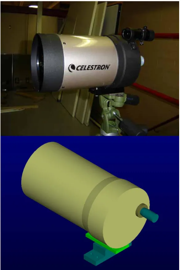
The telescope used in the Ice Detection T2 project is a Schmidt – Cassegrain Optical Celestron CS telescope (see figure 1). A Schmidt – Cassegrain telescope uses mirrors to reflect light within the telescope making use of the length of the telescope length three times, thus allowing for a shorter more compact telescope. A focus dial on the front face of the telescope moves the mirrors along a track and so adjusts the focus of the telescope. Although the focus dial on the telescope is capable of approximately 40 rotations it was decided by the project lead that approximately seven full rotations would be enough to adjust telescope within the range of changing distances for the current application of the project.
In order to in any way modify the Celestron Telescope, a method of attaching to the telescope is required. Because of the sensitive nature of the telescope it was decided not to in any way fasten to the telescope. Instead a lexan front plate will attach to the telescope using a collar of stemming lexan fingers that will extend over the front third of the telescope where there is some mechanical
reinforcement (see figure 2). These fingers will be a close fit and will be further held to the telescope using a long hose clamp that will wrap around the fingers and grip them in to the telescope. This fingers/collar piece will attach to the lexan front plate using both glue and small fasteners. Further attachments to the
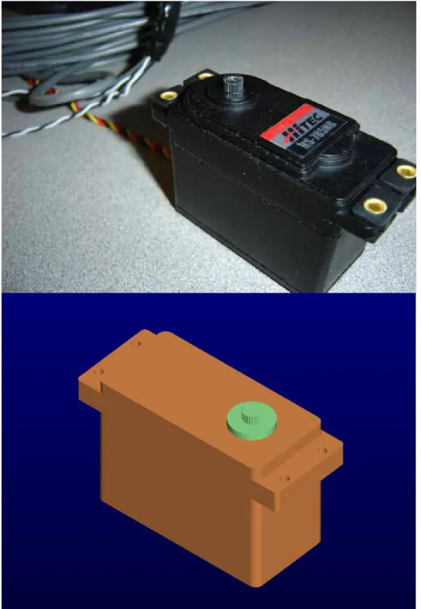
The electro-mechanical device capable of turning the focus dial on the telescope proposed by the electronics department is a HiTec HS-785HB Winch Servo (see figure 3). This servo offers 152.75 oz.in of torque, significant strength in shear and at least 1080 degrees rotational range (three rotations). The electronics department claim to be capable of achieving about 1800 degrees rotation (five rotations) using their own drive controller. Given this servo capability the remote focus dial adjustment was designed accordingly.
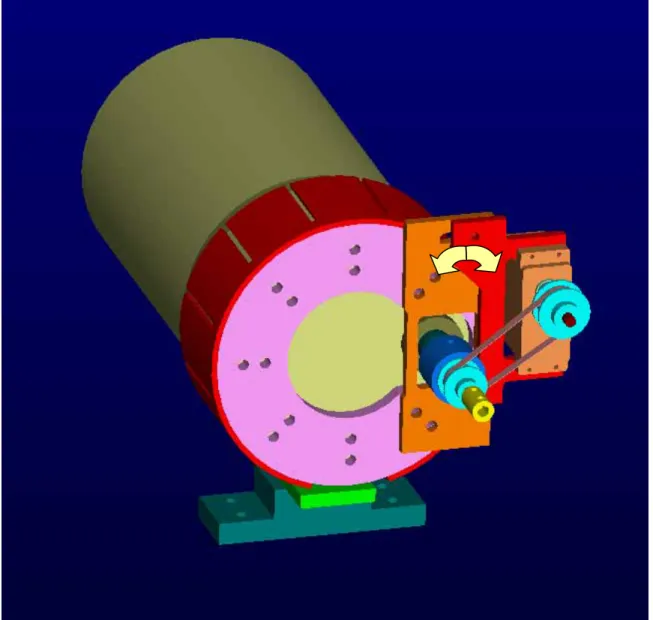
The challenge was to connect the winch servo to the focus dial translating approximately five rotations on the winch servo into seven rotations on the telescope dial. The basic design concept used to meet this challenge is a
system of toothed pulleys and a single sized, trapezoidal-toothed timing belt (see figure 2). One pulley is connected to the servo and another is locked onto the focus dial. The ratio between the sizes of the two pulleys is approximately 5:7 so that five rotations of the winch servo will yield seven rotations of the focus dial. The winch servo is mounted to a plate that can pivot about a lower point allowing the servo pulley to pivot towards and away from the dial pulley. The pivot plate can be locked on any pivot angle by simply tightening two screws. In order to tighten the timing belt the screws are loosened and the servo pulley is pivoted towards the dial pulley and the timing belt is looped over both pulleys. The plate is then pivoted away from the dial pulley by pushing with the hand. When the timing belt is snug tight (but not under any considerable load) the plate should be tightened in place. Testing the timing belt by rotating the servo will reveal if the
timing belt is tight enough. If the timing belt slips at all, loosen the screws. Apply a little more pressure to the pivot plate and retighten the screws. The timing belt should no longer slip. A potentiometer is also connected inline with the focus dial so that the focus of the telescope may be monitored in real time.
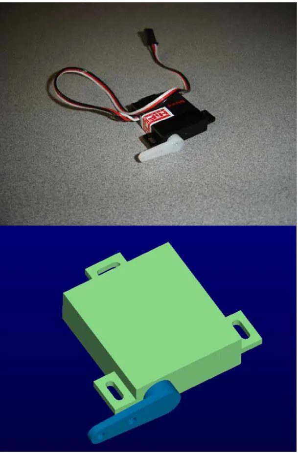
The second servo connected to the telescope is the HiTec HS-5125MG Digital Wing Servo (see figure 4). This servo is responsible for the sliding filter bar (see Appendix A, dwg 2096T52). When the filter bar is in the up position the optical filter is positioned between the camera lense and the telescope lense. When the filter bar is in the down position there is nothing between the camera lense and the telescope lense. The Digital Wing Servo turns only 90 degrees. An
extended arm is connected to the servo. This arm raises and lowers the filter bar over a 90-degree rotation of the servo. The digital servo can be pre-programmed to go directly to either the up position or the down position on the click of a
button. A supporting component has been designed to prop up the camera so that the weight of the camera does not pinch the filter bar and prevent it from sliding.
A simple telescope mount supports the telescope. Two bolts hold the telescope in place and four bolts hold the telescope mount to the base plate.
Also connected to the base plate is the video feed camera (see figure 5). The camera sits on an adjustable pan\tilt stand purchased to allow the camera to be
adjusted to point inline with the telescope and locked in place. It is intended that the camera should only need to be adjusted once so that it points in line with the laser and should be left in that position for extended periods of time.
The base place attaches to the bottom of the housing using several screws. Because the camera and laser both mount to the base plate it is intended that if necessary the base plate can be removed and returned to the housing without disturbing the alignment between the laser and the camera nor without needing to readjust the timing belt.
The housing for the telescope and camera is a modified design of another housing that has already been used at the Institute for Ocean Technology. A larger housing was used Technique 1 of the Ice Detection system and the design was found to function properly. Only the dimensions of this newer housing have been changed.
The weather resistant housing is shown in dwg 2096T42 contained in Appendix A. It is primarily composed of lexan. It has a thick bottom to which the base plate to the telescope is screwed. Buckles on the side of the housing tighten the top down. The back of the housing has a hinged door that opens down with hinges on the bottom edge. A waterproof hatch is attached to the door so that minor adjustments to the inner contents of the housing may be made if
The top of the housing has an overhanging ledge to shield the front glass, to a certain extent, from rain falling straight down.
3.0 – Components
There are a number of mechanical and electrical components needed for the telescope aspect of the Ice Detection T2 project. There are components that have been purchased or fabricated by the Institute already and there are
components in need of fabrication. There are also components that are yet to be purchased, some of which require some modifications. All components in need of fabrication or modification have associated drawings included under source file CAD_User\Projects\42_2096 Ice Detection\TOsmond\Telescope.ckd and are contained in Appendix A.
Already in possession by the Institute:
A Schmidt – Cassegrain Optical Celestron CS Telescope, An Optical Power Zoom Color DSP Camera,
A pan/tilt adjusting mount for the camera,
A HiTec HS-785HB Winch Servo that will be used to adjust the focus dial of the laser,
A HiTec HS-5125MG Digital Wing Servo,
A QuickSet Hercules tripod to which the weather resistant housing will mount, A Bourns 3540 Precision Potentiometer (see Appendix D).
Two pulleys and a timing belt must be ordered from McMaster-Carr (see Appendix D). Order:
1 x 6495K715, 1 x 6484K118.
The weather resistant housing for the entire system must be fabricated. The housing will be composed mostly of lexan, dwg 2096T43 – 2096T51, Appendix A.
Other components needing to be fabricated include:
A telescope faceplate with attaching fingers (a form of hose clamp will be necessary for this components), dwg 2096T31, 2096T32,
The winch servo plate and pivoting plate, dwg 2096T33, 2096T34,
The mount for the potentiometer and extensions for both the dial and the servo, dwg 2096T35 – 2096T37,
The mount for the digital servo and other associated pieces, dwg 2096T38, 2096T39,
The mount for the telescope (dwg 2096T40), the base plate (dwg 2096T41) and the modified filter bar (dwg 209653).
An Eye Piece Adaptor must also be fabricated. This piece is found under CAD_User\Projects\42_2096 Ice Detection\jb\eye piece adaptor.ckd and is also contained in Appendix A.
A list of all the fasteners needed to fully assemble all components is contained in Appendix C.
4.0 - Calculations
Pulley Gear Ratio
Servo Pulley – Pitch Diameter: 0.764” Telescope Pulley – Pitch Diameter: 0.955” Ratio: 0.955 : 0.764 = 1.25 : 1.0
Thus 5 rotations of the servo will generate 6.25 rotations of the telescope focus dial.
Length of Timing Belt
The length of the timing belt was calculated from the dimensions contained in Appendix B taken directly from the telescope CAD file.
Because the method of tightening the timing belt is through pivoting the pulleys closer and further away from each other two calculations must be made, one at each extreme angle. The following calculations were used to determine the necessary belt length:
Pulleys rotated in close together: 175.6° * π / 180 = 3.065 rads
θ r = 3.065 * 0.382 = 1.171“ 184.4° * π / 180 = 3.218 rads
2 * 2.487” = 4.974” 1 * 1.171” = 1.171” 1 * 1.538” = 1.538” 7.683”
Pulleys rotated far apart: 176.0° * π / 180 = 3.072 rads θ r = 3.072 * 0.382 = 1.173“ 184.1° * π / 180 = 3.213 rads θ r = 3.213 * 0.478 = 1.536” 2 * 2.703” = 5.406” 1 * 1.171” = 1.173” 1 * 1.538” = 1.536” 8.115”
Because the range of timing belt lengths passes through 8” over the full range of rotation it is clear that an 8” timing belt will pull tight as the pulleys are rotated apart. Therefore an 8” timing belt is to be purchased.
5.0 – Conclusions
This document has presented the design parameters for the modifications to the Celestron telescope used in the IOT Ice Detection projects. It has presented the design criteria, the materials used, the components used, described where they can be found, explained how the modifications are intended to function and presented the calculations used for the design work. Visual aids are included in the figures and in Appendix B. A complete set of drawings and a list of
necessary fasteners for the modifications are included in Appendix A and C. Parts required for purchase are contained in Appendix D. The design work included here will allow the telescope to be operated remotely. It will allow the operator to adjust the focus dial and to select the light intake by the camera through the telescope. The design of the water resistant housing will protect the telescope, cameras and other included electronics from wind and rain.
6.0 – Figures
7.0 – Appendices
Appendix A – Drawings
Appendix B – Timing Belt Dimensions Appendix C – Fastener List
Appendix B – Timing Belt Dimensions Pulleys rotated in close together
Appendix C – Fastener List
Number Type Length Connecting… Head
TELESCOPE
4 8-32 0.125 set screws for pulley sleeves socket set screw 4 8-32 1.500 small pulley plate screws socket screw 4 1/2-28 0.750 attaching servomount to main plate socket screw 4 6-32 0.375 side plate to main plate socket screw
4 2-56 0.625 servo to servomount socket screw
2 8-32 0.875 servomount to side plate socket screw 2 1/4-20 0.625 pot mount to back plate socket screw 2 2-56 0.500 slider slot to slider socket screw 1 2-56 0.375 sliding inside slider slot socket screw 3 2-56 0.500 thin servo to servomount socket screw 2 2-56 0.188 two pieces of the servo arm socket screw 2 1/4-20 0.500 angle bar to back plate socket screw 2 1/4-21 0.500 servo plate to back plate socket screw 1 10-24 0.750 tightening pivot plate socket screw 4 1/4-20 0.750 telescope to housing base socket screw
WEATHER HOUSING
10 8-32 0.625 front glass and back door to housing socket screw 4 1/2-20 0.500 tilt/pan head to stand button slot