A Device for Quantitative Assessment of Thumb
Ulnar Collateral Ligament Injury
by
Thomas Michael Cervantes
B.S. Mechanical Engineering
Massachusetts Institute of Technology (2011)
Submitted to the Department of Mechanical Engineering
in partial fulfillment of the requirements for the degree of
Master of Science in Mechanical Engineering
at the
MASSACHUSETTS INSTITUTE OF TECHNOLOGY
February 2018
@
Massachusetts Institute of Technology 2018. All rights reserved.
Auho..Signature
redacted
A uthor . . ...
Depart mnt of Mechanical Engineering
January 15, 2018
Certified
by...
Signature
redacted...
]exander Slocum
Walter M. May and A. Hazel May Professor of Mechanical Engineering
Thesis Supervisor
Accepted by
...
Signature redacted
'SKE1UVETT$~IN ITUTE
Rohan Abeyaratne
IN i OH C')
Quentin
Berg Professor of Mechanical EngineeringMITLibraries
77 Massachusetts Avenue
Cambridge, MA 02139 http://Iibraries.mit.edu/ask
DISCLAIMER NOTICE
Due to the condition of the original material, there are unavoidable flaws in this reproduction. We have made every effort possible to provide you with the best copy available.
Thank you.
The images contained in this document are of the best quality available.
A Device for Quantitative Assessment of Thumb Ulnar
Collateral Ligament Injury
by
Thomas Michael Cervantes
Submitted to the Department of Mechanical Engineering on January 15, 2018, in partial fulfillment of the
requirements for the degree of
Master of Science in Mechanical Engineering
Abstract
Injury to the Ulnar Collateral Ligament (UCL) of the thumb, known as "Skier's Thumb," is treated by surgical repair for complete tears, or by splinting for partial tears. Because of this radical difference in treatment options, diagnostic accuracy is critical. The primary mechanism of diagnosis is through a clinical assessment of joint integrity. This method requires a high degree of examiner skill and experience, and is inherently qualitative. Secondary diagnosis through magnetic resonance imaging (MRI) is often required to ensure accurate diagnosis. This additional testing delays the treatment and adds to the cost of care. A method to quantitatively assess the thumb UCL in a clinical setting is desired.
This thesis presents the deterministic design of a device to quantitatively mea-sure the stiffness of the thumb UCL. A stepper motor is used to rotate the thumb, while a cantilever load cell is used to measure torque. The device is designed to be operated by the physician, and has alignment features to properly orient the motor axis of rotation. Several safety features were incorporated into the device, including a magnetic breakaway that prevents applied thumb force from exceeding 10 N. The prototype was constructed, and preliminary testing was performed on healthy human subjects. Peak thumb torque was measured at 213.5 19.2 N-mm, and peak stiffness
was calculated to be 4.70 0.39 N-mm/degree. Potential pathways for further device
testing and improvement are outlined. The Thumb UCL Device has the potential to improve the speed of injury diagnosis and reduce the need for imaging studies. Thesis Supervisor: Alexander Slocum
Acknowledgments
The author would like to thank the following people for their contributions to this work: Prof. Alexander Slocum for supervising this project, providing the opportunity to TA for 2.75 and 2.70, and for his incredible mentorship over the years; Dr. Jay Connor for proposing the problem, and his long-standing collaboration with 2.75; Dr. Neil Gesundheit and the Stanford University School of Medicine for their flexibility and support for taking a leave of absence to complete this program; The Precision Engineering Research Group staff and students for their camaraderie and design feed-back; James, Amanda, Matthew, and Paul Cervantes (and the rest of the Cervantes family) for their humbling love and support in all of my endeavors; and Sarah Souther-land for countless design reviews, proofreading, and companionship throughout our cross-country adventures.
Contents
1 Background 13
1.1 Anatomy of the Thumb. ... 13
1.2 Injury of the Thumb UCL . . . . 14
1.2.1 Diagnosis . . . . 15 2 Design Process 17 2.1 Motivation . . . . 17 2.2 a-Prototype . . . . 18 2.3 Functional Requirements . . . . 19 2.4 P rior A rt . . . . 20 2.5 Ligament Biomechanics . . . . 21 2.6 Market Assessment . . . . 24
2.7 Strategies & Concepts . . . . 27
3 Device Description 29 3.1 O verview . . . . 29 3.2 Torque Application . . . . 30 3.3 Torque Measurement . . . . 31 3.4 Thumb Interface . . . . 33 3.4.1 Thumb Cradle . . . . 33 3.4.2 Metacarpal Cradle . . . . 38 3.5 System Integration . . . . 39 3.5.1 Shaft Coupling . . . . 39
3.5.2 Mounting Plate . . . . 3.5.3 Housing . . . . 3.6 Electronics . . . . 3.6.1 Motor Driver . . . . 3.6.2 Instrument Amplifier . . . . 3.6.3 Microcontroller . . . .
3.6.4 Bluetooth Serial Communication
3.7 Prototype Assembly . . . .
4 Device Evaluation
4.1 Component Validation . . . . 4.1.1 Load Cell Calibration . . . .
4.1.2 Magnetic Breakaway Testing . . .
4.2 Human Subjects Testing . . . .
4.2.1 Protocol . . . .
4.2.2 Results. . . . .
5 Conclusion
A Design of Medical Devices 2018
B Part Drawings
C Circuit Wiring Schematic
D Arduino Code E COUHES Forms 42 42 45 46 47 47 48 49 53 53 53 54 55 55 . . . . 57 61 65 69 77 79 87 . . . . . . . .
List of Figures
1-1 Bony anatomy of the hand [251 . . . . 13
1-2 A) Detailed view of the UCL [81; B) Drawing of a torn UCL [71 . . . 14
2-1 a-prototype of the Thumb UCL Device . . . . 18
2-2 Diagram of the forces acting on the thumb UCL . . . . 21
3-1 CAD Renderings of the full Thumb UCL Device . . . . 29
3-2 A) NMB PG15S stepper motor; b) Switching logic; C) Wire color coding 30 3-3 A) Futek cantilever load cell; B) Wheatstone bridge wiring diagram . 33
3-4 Thumb Cradle with a magnetic breakaway design. A) Thumb cradles attached to the Futek load cell; B) Square magnet version; C) Round m agnet version . . . . 34
3-5 Drawing of the thumb cradle showing the ellipse used to drive the overall dimensions based on anthropometric data . . . . 35 3-6 Design evolution of the thumb cradle . . . . 35
3-7 Force Diagram of the Magnetic Break-Away Concept . . . . 36
3-8 Thumb cradle assembly setup. The magnet placed on the outer surface acts as a clamp to keep the cradle aligned to the steel plate. . . . . . 39 3-9 Metacarpal cradle showing the gothic arch groove shape that constrains
rotation about the UCL axis . . . . 39 3-10 Shaft coupling designed to couple the motor and load cell . . . . 40
3-11 Design evolution of the shaft coupling: Version 01 (top), Version 02
(middle), and Version 03 (bottom). Final design is shown in the pre-vious figure. . . . . 42
3-12 Mounting plate for the motor, housing, and metacarpal cradle . . . . 43
3-13 Mounting plate assembly showing the positions of the motor and metacarpal cradle . . . . 43
3-14 Housing Top Details . . . . 44
3-15 Electronic components: A) Pololu A4988, B) SparkFun BlueSMiRF, C) Arduino Nano, D) SparkFun HX711 . . . . 45
3-16 Accessory electronic components: A) switch, B) button, C) power jack 45 3-17 Breadboard assembly of the electronic components used for testing & validation . . . . 46
3-18 Fully assembled p-prototype of the thumb UCL device. . . . . 49
3-19 Fully assembled 3-prototype of the thumb UCL device. . . . . 51
3-20 Prototype using the larger stepper motor version . . . . 51
3-21 Detailed view of the components specific to the large prototype version: A) mounting plate; B) shaft coupling; C) housing. . . . . 52
4-1 Testing setup to determine the thumb cradle magnetic breakaway force 55 4-2 Representative plot of torque and stiffness vs angle for a test subject 58 C-1 W iring Schematic . . . . 77
List of Tables
2.1 Functional Requirements for the Thumb UCL Device . . . 2.2 UCL Biomechanics Calculations . . . . 2.3 Market Analysis for a Thumb UCL Diagnostic Tool . . . .
2.4 Market Analysis for a Fetal Laceration Prevention tool . .
3.1 Strain Gauge Analysis . . . .
3.2 Thumb Cradle Magnetic Breakaway Analysis . . . .
3.3 Assembly steps for the magnetic thumb cradle . . . . 3.4 Motor Shaft Stress Analysis . . . .
3.5 Inputs and Outputs to the Arduino Nano . . . .
3.6 Bill of Materials for the Thumb UCL Device . . . . 4.1 Protocol for human subject testing . . . . 4.2 Average peak values of torque and stiffness for a test subject
deviation shown in parentheses (N=4 measurements per hand) . . . .
. . . . 19 . . . . 22 . . . . 25 . . . . 26 32 37 38 41 47 50 56 59 Standard
Chapter 1
Background
1.1
Anatomy of the Thumb
The bones of the thumb include the first metacarpal, proximal phalanx, and distal phalanx. The thumb articulates with the carpal bones of the wrist via the carpo-metacarpal (CMC) joint. The metacarpo-phalangeal (MCP) joint is located between the first metacarpal and the proximal phalanx. Movements of the thumb include flexion, extension, abduction (moving away from the fingers), adduction (moving towards the fingers), and opposition (moving across the palm).
Disg phariqas
Intermediate phalanges J
Proximal phalanges MCP joint
Metacarpals
CMC joint
Carpals
The thumb ulnar collateral ligament (UCL) is located at the MCP joint. As shown in Fig. 1-2, it attaches to the first metacarpal and proximal phalanx, oriented roughly longitudinally. The UCL is located on the ulnar side of the thumb (towards the fingers); a corresponding radial collateral ligament is located on the opposite side. Of note, there are ulnar collateral ligaments located elsewhere in the body (i.e. fingers, elbow). Any mention of the UCL without a qualifier is intended to refer to the thumb UCL.
A
B
Collateral rigament
Accessory Flexor tendon
colateral ligaments Volar plate
Figure 1-2: A) Detailed view of the UCL [8]; B) Drawing of a torn UCL [71
1.2
Injury of the Thumb UCL
Injury to the thumb UCL is commonly known as "Skier's Thumb" due to a high incidence among skiers. This injury represents 5-10% of all skiing injuries [12], and is the second most common ski injury overall (behind knee injuries) [10]. Overall, roughly 200,000 cases per year of thumb UCL injury are estimated to occur in the
US [161.
The most common mechanism of UCL injury is sudden, forceful abduction of the thumb, such as falling on an outstretched hand while grasping a ski pole. Many other sports also have high risk for UCL injury, such as football, basketball, and hockey [14]. Chronic repetitive strain of the ligament can also result in injury; historically, the injury was referred to as "Gamekeeper's Thumb" because the motion used to
snap the necks of game birds would frequently cause this injury over time [221. The severity of injury can vary from a partial tear to complete rupture of the ligament.
1.2.1
Diagnosis
Physical Exam Technique
The diagnosis of Skier's thumb begins with a direct physical exam by a hand surgeon. The physician stabilizes the metacarpal while applying a radial stress to the thumb. The variables assessed during this test are 1) maximum joint angle, and 2) end-point stability. The joint angle is measured between the metacarpal and proximal phalanx of the thumb; an absolute angle of 30', or 15-20' greater than the non-injured thumb, is indicative of a tear [24]. The end-point stability is determined through tactile feedback; a "hard" endpoint at maximum displacement indicates an intact ligament, while a "soft" endpoint indicates a tear [18]. This determination is inherently qualitative; no quantitative measure for assessing end-point stiffness currently exists.
Imaging
X-ray images of the thumb are obtained for all patients with suspected UCL injury. They are often taken before physical examination to rule-out any avulsions', which could be exacerbated by the physical exam technique described above.
If the physical exam cannot definitively distinguish a full vs partial tear, MRI is
used as the gold standard for diagnosis. MRI has been shown to have >90% sensitivity and specificity for identifying tears of the UCL [21]. However, MRI is expensive and exposes the patient to radiation, and generally not indicated unless the physical exam cannot definitively distinguish between a full and partial tear.
Ultrasound imaging can be used as a faster, less expensive alternative to MRI. However, the sensitivity and specificity are 76% and 81%, respectively, for diagnosing
UCL tears [6].
1An avulsion is a piece of bone at the base of a ligamentous attachment that fractures due to
Chapter 2
Design Process
2.1
Motivation
The topic of this thesis was motivated by a project form the Fall 2016 course "Medical Device Design (2.75)". In this course, physicians present a clinical problem from their practice to a group of engineers, who form teams and spend a semester designing a solution. Dr. Jay Connor, a hand surgeon, initially proposed the problem of diagnosing injury to the thumb UCL. A team of four students I were assigned to this project; the author served as a engineering and clinical mentor, as well as the Teaching Assistant for the course. The class culminated with a a-prototype, which performed successfully in preliminary testing.
The project is continued in this thesis, with the goal of producing a -prototype consisting of iterative design improvements, and performing initial human subjects testing to assess the clinical feasibility. The project also affords an opportunity for the author to combine engineering fundamentals with clinical perspective, to produce a working mechanical prototype ready for in-depth clinical assessment.
'Team members were Woojeong Elena Byun, Ava Chen, Kristina Kim, and Kaitlyn Nealon. The mentorship team consisted of Thomas Cervantes, Daniel Teo, Tyler Wortman, Alexander Slocum, and Dr. Jay Connor.
Figure 2-1: a-prototype of the Thumb UCL Device
2.2
a-Prototype
The a-prototype designed as part of the 2016 2.75 course is shown in Fig. 2-1. The device uses a gearmotor with a 900 bevel gear train to apply a torque to the thumb. Thumb angle is measured with an encoder, and torque is calculated from the motor current. Preliminary testing on a simulated thumb MCP joint showed reliable detection of differences in stiffness. For further details, see Appendix A for a conference paper that describes the device (accepted by the 2018 Design of Medical Devices Conference). Testing of the a-prototype highlighted a number of opportunities for improvement:
e The size and weight was cumbersome for many to use
* The orientation of the hand used to operate the device was uncomfortable
e The data recorded during testing could not be easily exported
o Securing the thumb in the cradle was difficult
* Switching the thumb cradle from left to right was time consuming
e The motor control algorithm was jerky and unpredictable
These observations provided a helpful starting point for the design of the /3-prototype. Although many design features were kept, a re-evaluation of the higher-level strategies was conducted for thoroughness.
2.3
Functional Requirements
A deterministic design process was used throughout the project to evaluate design
decisions. The first step was to define the functional requirements of the device, which are the minimum set of conditions that must be satisfied for the solution to be successful. At the beginning of the -prototype design process, these functional requirements were reevaluated and adjusted based on the preliminary testing from the 2.75 project. Table 2.1 shows the updated list.
Table 2.1: Functional Requirements for the Thumb UCL Device
Functional Requirement Description
1. Accurately & reliably quantify UCL injury
" Measure thumb angle
" Measure thumb torque Torque & angle used to calculate stiffness " Stable interface to hand Avoid misalignments that may skew data " Examiner independent Should be an improvement over the
current examiner-dependent process 2. Easy to use
" Ergonomic operation Comfortable for a wide range of users
& patients " Easily switch between left/right
" Minimal size & weight a-prototype testing indicated that the bulky size and heaviness impeded proper use
3. Safe
" DOES NOT increase damage to UCL
" Simple to turn off "Dead-man's switch" to turn off if not actively controlled
" Biocompatible materials
4. Feasible for clinical use
" Fits into clinical workflow Does not require significant time, resources, or training to implement
" Cost appropriate Components do not prohibit appropriate pricing
2.4
Prior Art
Another important aspect of a deterministic design process is a thorough investiga-tion into the prior art. In addiinvestiga-tion to researching the clinical background & context, devices that aim to solve the same problem (or similar) should be sought and evalu-ated. This section highlights some devices found during review of the academic and patent literature that proved relevant for this project.
In one study, a soft actuator was used in a device for thumb rehabilitation after stroke
[15].
The actuator, which was controlled by varying pressure, aimed to mimic a natural movement of the thumb by combining flexion, rotation, and skin stretching. The device was attached to the hand via malleable aluminum straps, secured by Velcro. The soft actuator is a useful design parameter for achieving natural, multi-axis motion; however, it is less applicable for the Thumb UCL device because highly constrained motion in one plane is desired. The malleable aluminum attachment mechanism allows a high degree of customization per patient, and could perhaps achieve better orientation & stabilization than the cradle method used in the o-prototype.Another study used a custom wrist orthosis to measure the torque required for passive abduction of the thumb CMC joint (proximal to the MCP joint) f27]. The orthosis was comprised of an aluminum base frame, with linkages used to position an external torque measurement device (CDI Multitorq) over the joint. The thumb was manually actuated by the investigators. The external torque measurement was an interesting design parameter for obtaining reliable, accurate torque measurements. Similarly to
[15],
the aluminum frame/linkages provides a high degree of customization per patient. However, adjusting the device for each patient might prove tedious and cumbersome. The external measurement device is also expensive, and could prove difficult to integrate into a streamlined solution.In another soft robotic device, strain gauges were used to measure the flexion angle of the ankle [20]. The application required measurement of large strains over a flexible surface, so a custom solution was designed using micro-channels of a liquid
metal alloy embedded within a silicone elastomer. This design parameter could prove useful for this application at the Thumb MCP joint; however, the cost and resources of building the custom sensor could prohibit production scaling.
2.5
Ligament Biomechanics
A primary functional requirement for the Thumb UCL Device is to avoid further
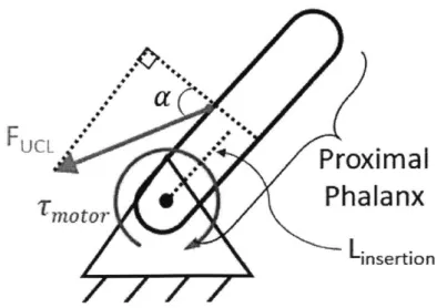
damage to the ligament during testing. An analysis of the forces acting on the joint was conducted to approach the problem in a deterministic manner. Figure 2-2 shows a force diagram of the thumb MCP joint. The MCP is modeled as a pinned joint with a fixed base. The UCL inserts along the proximal phalanx of the thumb at a distance, L, from the center of rotation, and at an insertion angle of a. From this representation a force balance can be constructed to determine the maximum allowable motor torque, -r,7 as shown in Eq. 2.2-2.4:
FUCL
Proximal
Phalanx
motor
Linsertion
7amotor = Fmax * cos(a) * L
Fmax
Umax A
Fmax = max * A
Tr"ax =max * A * L * cos(a)
(2.1) (2.2)
(2.3)
(2.4)
Fmax is the maximum force on the UCL; -max is the failure stress of the UCL.
Equation 2-2 was used to create a design spreadsheet for calculating a target motor torque. A stiffness of 81 N/mm was calculated for an average intact UCL using values published in the literature. If a ligament is 50% torn, an maximum of
288 N-mm can be applied before risking further injury. The true value is likely larger
due to conservative estimates for ligament insertion length and angle, which were not found in literature.
Table 2.2: UCL Biomechanics Calculations
UCL Stiffness Estimations
Parameter Value Units Notes
Young's modulus 37.3 N/mm2 [11]
Diameter 6 mm [26]
Area 28.3 mm2
Length 13 mm [26]
Stiffness 81.1 N/mm K AF
Maximum Torque Estimation
Failure load 266 N [26]
Failure Stress 9.4 N/mm2
UCL insertion length 4 mm estimate 1/3 of length
UCL insertion angle 60 0 conservative estimate
Torque Limits
Area
(%
max) Max Torque (N-mm)100 576
75 432
50 288
25 144
Another primary functional requirement for the device is to accurately quantify
UCL injury. Thumb torque and angle are used to calculate the stiffness of the MCP
joint as a surrogate for stiffness of the UCL. However, a possible source of error is "parasitic" stiffness due to swelling from an acute injury. The effect of a parasitic stiffness is analyzed below.
The total stiffness of a healthy and torn MCP joint are defined as:
Khealthy = Kskin + Kmuscie + KUCL (2.5)
Ktear Kskin + Kmuscle + (1 - 'y) * KUCL + Ksweii (2.6)
Khealthy is the total stiffness of a healthy MCP joint; Kkin is the stiffness of the
skin surrounding the joint; KUCL is the stiffness of a healthy UCL; Kswell is the
stiffness from joint swelling; -y is the percent tear of the UCL.
Patients with a thumb UCL injury can be expected to have a healthy thumb for comparison on the opposite hand. Thus, a calculation of the percent difference between healthy and injured thumbs, %A, can be performed and used to solve for the percent tear of the UCL:
Khealthy - Ktear _ -yKUCL - Kswell (2.7)
Khealthy Khealthy
%A * Khealthy Ksweii
-= (2.8)
KUCL KUCL
Equation 2.8 demonstrates that parasitic stiffness from joint swelling is a potential risk to accurate measurement of UCL tears. Additionally, the stiffness of a healthy
UCL ligament is needed; although the stiffness was calculated in Table 2.2, the
stan-dard variation in the population is unknown. As a countermeasure to this problem, cadaver studies are needed to determine the full range and population statistics of
2.6
Market Assessment
Perhaps one of the most challenging aspects of medical device design is the need to understand the regulatory and reimbursement pathways unique to the field. Often, the person who uses the device (the physician) is different from the person purchasing the device (the hospital/clinic); the person benefiting from the device (the patient) is different from the person paying for it (the insurance company). The incentives of each stakeholder are not necessarily aligned, and the true cost is frequently obscured from multiple parties.
The proposed Thumb UCL device has an interesting value proposition; it aims to provide benefit by improving speed of diagnosis, and reducing need for MRI imaging. As a patient and physician, both of these are desirable. As organizational entity (i.e. hospital), the benefits are less clear; improving the speed of diagnosis could increase the quantity and frequency of surgical procedures, which are often profitable. However, reducing the need for MRI means that this cannot be billed to the insurance (some healthcare organizations use imaging centers as a means for building revenue
[13]).
From the perspective of insurance and reimbursement, the device could save money
by decreasing payouts for imaging. The device introduces a new procedure to the
clinical encounter; a new CPT2 code would need to be created in order to bill for it. Many new medical devices seek this route, but the process takes time and resources. These considerations were further researched and incorporated into a spreadsheet, shown in Table 2.3. The total cost burden of hand MRIs ordered for indeterminate physical exam testing is on the order of $30 million. This could represent a savings opportunity for payers. If the device was sold to all hand surgeon practices in the
US, at a price of $500, the total market opportunity is in the range of $310,000. This
number represents a lower bound, as other healthcare organizations besides hand surgery clinics may find utility in the device (emergency departments near ski areas, family practice/sports medicine clinics). Although the scope for market expansion
2
CPT = Current Procedural Terminology. CPT codes are used to define different medical services
Table 2.3: Market Analysis for a Thumb UCL Diagnostic Tool
Parameter Value Notes
Hand surgeons in the US 3100 [1, 231
Estimated #surgeons/practice 5 likely to vary widely Hand Practices (US) 620
UCL injuries/year (US) 200,000 [16]
Rate of diagnostic difficulty 27% [17] Patient candidates for device 54,000 (per year)
per surgeon 17.4
per practice 87.1
Hand MRI Cost: [3]
nominal $630
min $504
max $1,575
Total Potential cost burden (per year)
nominal $34.OM
min $27.2M
max $85.1M
Theoretical CPT fee ratio 10% compared to MRI fee, conservative estimate
CPT Fee per procedure $63
Theoretical cost of device $500
#
patients to recoup cost 7.9Market opportunity $310K if sold to practices
is limited, there is currently no direct competition in the space. However, there is support from current hand surgeons (including Dr. Conner, the project proposer) for development of the device as a useful clinical tool. In contrast, the following section describes a case study where preliminary market research showed promise, but interviews with physicians indicated an unfavorable outlook.
Case
Study: Fetal Laceration Analysis
Initial work for this thesis was focused on an opportunity to reduce fetal laceration injuries during Cesarean-section, motivated by clinical observations. Accidental fetal
lacerations can occur when the uterus is incised by a scalpel blade; if the surgeon uses too much force while cutting, the fetus can be inadvertently harmed once the blade has passed through the uterine wall. Risk of this injury is increased if the C-section is
Table 2.4: Market Analysis for a Fetal Laceration Prevention tool
Parameter Value Notes
#
births/year (US) 3,988,076 2014 census data [19]#
C-sections/year 1,284,551 2014 CDC data [191 Rate of emergent C-sections 9.5% [291Fetal laceration rate (all) 1.1%
Fetal laceration rate (emergent) 3.0%
[91
Lacerations/year (all) 14,130 Lacerations/year (emergent) 3661
Serious complication rate
(%)
0.062 moderate to severe[9J
Serious complications/yearlower bound 226
upper bound 874
average 550
#
hospitals performing obstetrics 3760 estimate 2/3 of all hospitals [5, 30]Malpractice costs per complication $500,000 [2] Total cost for laceration lawsuits $275M per year
Risk per hospital $73,170
Risk per C-section (all) $214 Risk per C-section (emergent) $2,254
CSAFE cost $28
Market opportunity (emergent) $3.4M per year
performed on an emergent basis, where stress is often high and there is time pressure to complete the delivery.
When searching for prior art during the early design phase, a seemingly simple, low-cost, and effective solution was identified. However, the device (CSAFE) had not gained much traction with obstetricians (OB-GYNs). A market analysis, shown in Table 2.4 was performed to determine feasibility; up to 550 serious complications from fetal lacerations may occur per year, and on average each hospital faces a risk of
$70,000 per year from lawsuits. This corresponds to a risk of $2,200 per emergency
C-section. These numbers are conservative estimates, drawn from available literature sources; however, the true rate of fetal lacerations is likely larger, since hospitals are not incentivized to publish data about their complications.
Initially, the market assessment pointed to a favorable opportunity; hospitals stood to lose a nontrivial amount of money due to fetal lacerations. Furthermore, the
CSAFE device retailed at $28, only 10% of the risk per emergent C-section.
How-ever, discussions with several OB-GYN physicians revealed factors which may have hindered its adoption as a preventative measure.
While physicians acknowledged that fetal lacerations are a problem, they did not consider themselves (or their hospitals) to be at risk. One physician pointed out that the highest risk is likely at low-volume centers, where C-sections are performed less frequently, and fewer resources may be available in case of emergencies. Ultimately, a different project (the Thumb UCL device) was pursued instead due to lack of interest from a primary stakeholder.
2.7
Strategies & Concepts
Design of the Thumb UCL Device was conducted using a coarse-to-fine methodology. High-level strategies and concepts were evaluated based on the functional require-ments, first-principle analysis, literature review, and a comparison of risks & coun-termeasures before conducting more detailed engineering design. For the -prototype design phase, the primary high-level strategy that was reevaluated was active vs pas-sive torque application.
The original decision for an active torque application solution (i.e. motor) was made based on the recommendation of the physician who proposed the project. The primary advantage of this approach is simple, streamlined operation from the user per-spective. Engineering challenges include component integration and ensuring smooth, safe motor control. A potential risk is the addition of expensive components (motor & associated driver), which could prohibit appropriate pricing.
A passive actuation strategy (i.e. doctor moves the thumb) has some distinct
advantages; there is reduced risk of over-torquing the thumb, since the physician can use tactile feedback to control thumb rotation. The cost is potentially reduced since an actuator component is not needed. However, a passive strategy would require an elaborate fixation device, similar to the design in
[27],
that would increase the set-up time and training needed for operation. Ultimately, an active actuation strategy waschosen for the purposes of this thesis. However, a passive alternative could be a viable alternative if the cost of an active device proves unfeasible.
At a concept level', the primary design change considered was patient vs physician control of the device. The a-prototype was designed for patient control with the aim of providing an additional measure of safety; the patient can immediately stop the device if the rotation becomes too painful. A risk for this approach is that the patient does not properly orient the device on the thumb, which could skew the data.
A possible countermeasure would be to design a fixturing jig for the hand to ensure
that the patient maintains proper positioning throughout the procedure.
A physician-operated approach would reduce the risk of improper device
orien-tation; a hand surgeon could easily identify the relevant anatomical landmarks and position the device appropriately. However, patients may feel apprehensive if their injured thumb is being moved by a motor without their control. After considering both approaches, a physician-operated device was ultimately chosen. Countermea-sures to reduce the risk of patient injury & discomfort were factored into the design of several components, as described in Chapt. 3.
3
Here, a "concept" is defined as more granular than a strategy. In order from coarse to fine:
Chapter 3
Device Description
3.1
Overview
The redesigned Thumb UCL device is shown in Fig. 3-1. The device is operated
by the physician, and controlled through a button mounted on the top of a vertical
handle. A direct-drive stepper motor is used to actuate a load cell, which measures the torque being applied to the thumb. The thumb is held in a magnetically-attached cradle, which is designed to break-away at ION of force. During testing, real-time data is transmitted wirelessly via Bluetooth to a nearby phone or computer. Part drawings for all custom components are included in Appendix B.
3.2
Torque Application
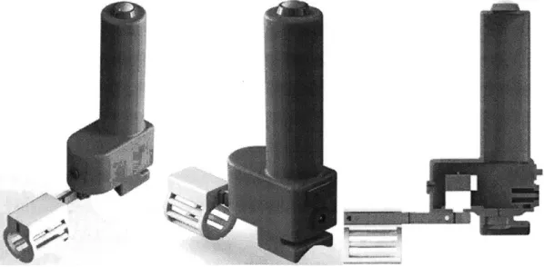
One of the critical modules focused on for re-design was the motor; in a-prototype, the motor was principle driver of the overall dimensions. The Pololu gearmotor used had a stall torque of 1765 N-mm, with dimensions of 37Dx52Lmm. Based on calculations from Section 2.5, the torque specification is much higher that is necessary, or safe. At a minimum, the motor needs to apply enough torque to evaluate the linear stiffness of the joint. At a maximum, the applied load should not exceed the yield stress of the ligament, especially when partially torn. Based on calculations in Table 2.2, a conservative torque maximum of 150 N-mm was chosen; this would avoid risk of further ligament injury for tears up to 75% surface area.
In addition to downsizing the motor torque and dimensions, the motor type was considered. For this application, the motor needs to operate at slow speeds on the order of 1rpm or less, with high resolution. Full, continuous rotation is not required.
A servomotor or Stepper motor are well-suited for these criteria. Motor catalogs
were searched with these parameters, while optimizing for the the smallest possible dimensions.
Ultimately, the NMB PG15S Stepper motor, shown in Fig. 3-2, was chosen for its small size and peak hold torque of 150 N-mm. The motor operates at 15V, with a current rating of 100mA. The motor also has high step resolution, with 2048 steps per revolution.
A
#
IB
C
co~ BLK BRN RG YEL 1 - + + -2 -+ -+ 3 + - - + 4 SWirCHING SEQUENCE VIEWED FROM MOUNTING SURFACE Figure 3-2: A) NMB PG15S stepper motor; b) SwitchingWire Color Motor
Black Al
Brown A3
Orange B1
Yellow B3
logic; C) Wire color coding
maximum of 150 N-mm is based on the yield stress of the UCL ligament. However, other structures in the thumb contribute to stiffness about the MCP joint, as described in Section 2.5. To account for this possibility, a larger motor in the same family was evaluated. The Minebea PG25L stepper motor has a holding torque of 450 N-mm and a modest size increase (25mm diameter vs 15mm).
The remainder of this section discusses design of components to interface with the smaller 150 N-mm motor. The corresponding components for the larger motor were also designed in parallel, using the scaling ability of the deterministic design process.
3.3
Torque Measurement
The decision to use a stepper motor necessitates a change in torque measurement technique. In the a-prototype, torque was derived from motor current measurements. However, a stepper motor draws full current continuously. A direct method of torque or force measurement is needed.
Strain gauges were investigated as a possible design parameter for this functional requirement. Advantages of this approach include a small form factor, and the flexibil-ity to design custom shapes. A primary risk is the low signal amplitude derived from a strain gauge sensor; the required amplification can result in a low signal-to-noise ratio.
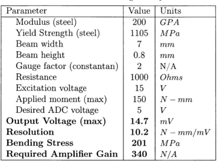
An analytical approach was used to determine if a feasible strain gauge config-uration could be achieved given the constraints of the system. Equation 3.3 shows the relationship between the output voltage of the strain gauge and the relevant parameters: 1 Vout = -G *6* Ve (3.1) 2 GM = 6M(3.2) Ebh2 3G Vout = M *V (3.3) Ebh2 ex
Table 3.1: Strain Gauge Analysis
Parameter Value Units
Modulus (steel) 200 GPA
Yield Strength (steel) 1105 MPa
Beam width 7 mm
Beam height 0.8 mm
Gauge factor (constantan) 2 N/A
Resistance 1000 Ohms
Excitation voltage 15 V
Applied moment (max) 150 N - mm
Desired ADC voltage 5 V
Output Voltage (max) 14.7 mV
Resolution 10.2 N - mm/mV
Bending Stress 201 MPa
Required Amplifier Gain 340 N/A
V, is the output voltage from the strain gauge circuit, G is the Gauge factor (specific to the material used, typically Constantan), epsilon is the strain experienced from an applied moment, M; Vx is the excitation voltage; E is the Young's modulus of the beam material; b is the beam width, h is the beam height.
A design spreadsheet was created using this equation. The maximum possible V.,
is desired; a value of 150N - mm was used for the applied moment based on the peak
holding torque of the NMB stepper motor. Table 3.1 shows a feasible configuration that was determined.
A small beam width of 0.8mm is needed to achieve a feasible amplifier gain. With
a beam this thin, plastic yielding of the material is a significant risk -with a bending stress of 201 MPa, a hardened material such as 17-4 PH stainless steel is needed, and an aluminum alloy would not be usable. However, the design table demonstrates that the strain gauge strategy is overall feasible.
A cantilever load cell from Futek (FSH00889), shown in Fig. 3-3, was selected to
meet these strain gauge criteria. The load cell has an integrated Wheatstone bridge, and an overall size that integrates well with the rest of the device.
AB
r+ Excitaton l(Rec" odg Sensor + Signal (Blasck)
r Excitation Nite
Shield (Floating)
Figure 3-3: A) Futek cantilever load cell; B) Wheatstone bridge wiring diagram
3.4
Thumb Interface
3.4.1
Thumb Cradle
The thumb cradle interacts with phalanges of the thumb to transfer the motor torque to the MCP joint. The a-prototype thumb cradle consisted of a semicircular shape that was attached to the device via screws, and secured to the thumb using Velcro. To switch between right- and left-handed operation, the cradle had to be unscrewed and flipped in a cumbersome, time-consuming process. The thumb cradle was redesigned to improve upon this feature, while maintaining patient safety.
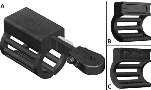
A magnetic breakaway concept for the thumb cradle attachment was explored and
implemented. Figure 3-4 shows CAD renderings of the design. Neodymium magnets are used to attach the thumb cradle to the stainless steel load cell. With embedded magnets, the thumb cradle is easy to attach/detach, which facilitates easy swapping of different sizes. Bilateral cradles are used to obviate the need for different left/right configurations. Additionally, the magnets serve as a torque "fuse"; if the applied force exceeds a predetermined threshold, then cradle will detach. In this way, the magnetic breakaway concept satisfies multiple functional requirements; it provides a mechanism for patient safety, and it allows for simple attachment/removal.
The dimensions of the thumb cradle are driven by the load cell size and by er-gonomic principles. The "semicircle" is actually an ellipse with the major and minor radii set based on anthropometric tables [281. Initial prototyping was done using the average of the 5 0th percentile male and female dimensions. The prototypes were able
A
B
N
w
c
Figure 3-4: Thumb Cradle with a magnetic breakaway design. A) Thumb cradles attached to the Futek load cell; B) Square magnet version; C) Round magnet version
to accommodate the test subject sample used in this study. The CAD model of the thumb is constructed such that the ellipse dimensions can be modified with minimal reconfiguration needed in the rest of the body, as shown in Fig. 3-5.
Several rounds of design iteration were employed before converging on the final thumb cradle configuration. Figure 3-6 shows different stages of the cradle design. Initially, the magnets were designed to attach from the top, and a symmetric design would be used to eliminate the need for left/right switching (Fig. 3-6A). However, the magnets are oriented such that applied force is perpendicular to the magnetic force; the cradle would "slide" off of the device. This poses a difficult analytical scenario, as magnets are typically rated for perpendicular pull force only. Although an acceptable configuration could be determined through brute-force prototyping, a closed-form analytical model is desired.
The next iteration (Fig. 3-6B) used magnets that were oriented parallel to the direction of force application, which would adhere to the model in Fig. 3-7. However, Velcro was still needed to secure the thumb to the cradle, a step that is ideally eliminated. The final semi-circular configuration (Fig. 3-6C) removes the Velcro requirement, but does pose the risk of sizing mismatches for very large or small thumbs. As a countermeasure, multiple sizes (small, medium, large) could be provided
18.50 -
----21
Figure 3-5: Drawing of the thumb cradle showing the ellipse used to drive the overall dimensions based on anthropometric data
C
Figure 3-6: Design evolution of the thumb cradle
to the user. The design spreadsheet for selecting the magnets easily accommodates these changes.
Magnetic Breakaway Force Analysis
As with all engineering modules, the FRDPARRC approach was used to guide deter-ministic selection of the magnets for a desired breakaway force. Figure 3-7 shows the forces acting on the thumb cradle. The applied force of the motor acts through the center of the cradle, where the midline of the thumb is in contact. The magnetic force acts through the midline of the magnets, oriented perpendicular to the face of the load cell. Gravity acts on the center-of-mass of the cradle, which can be determined from the solid model.
Rmag
Fmag
Raapplied
Figure 3-7: Force Diagram of the Magnetic Break-Away Concept
In this diagram, the top-left corner of the thumb cradle is the rotation point. A simple force balance can then be used as shown in Eq. 3.4:
Fmag Rmag = Fapp Rapp cos(Oapp) + FgRcoM sin(OCOM) (3.4)
Fmag = (1/Rag) * [FappRapp cos(app) + FgRcoM sin(ocoM)] (3.5)
Fmag = SF(1/Rmag) * [FappRapp cos(6app) + FgRcOM sin(ocoM)1 (3.6)
Fmag is the holding force of the magnet(s), Rmag is the distance between the rotation point and center of magnetic force application, Fapp is the applied force on the thumb (from the motor); Rapp is the distance between the rotation point and the center of applied force; Oapp is the angle of applied force (relative to vertical; F is the force due
to gravity, RCOM is the distance between the rotation point and the center of mass;
9COM is the angle of the center of mass (relative to vertical); SF is the shape factor. A design spreadsheet was then constructed to evaluate magnets with a range
of sizes and shapes. Table 3.2 shows the results for some of the magnets tested. Preliminary testing with the D42SH magnet revealed a breakaway force of roughly 5
Table 3.2: Thumb Cradle Magnetic Breakaway Analysis Magnet Details (supplier: K&J Magnetics)
Magnet Name D42SH D44-N52 BX044-N52
Pull force (N) 10.2 18.5 72.4
Diameter (mm) 6.35 6.35 6.35
Thickness (mm) 3.2 6.4 6.4
Weight (gm) 0.754 1.51 7.68
Thumb Cradle Details
Moment arm (mm) 23.09 23.09 23.09
Angle (degrees) 27.0 27.0 27.0
Mass (gm) 4.22 5.02 4.44
#
magnet slots 3 3 1Rotation point z-offset (mm) 5.7 5.7 5.7
COM x-coord (mm) 6.49 7 7.28
COM z-coord (mm) 9.81 7.9 8.94
COM moment arm (mm) 16.8 15.3 16.4
COM angle (degrees) 22.7 27.2 26.4
Magnetic Force Calculations (see Eq. 3.4)
Desired Max Force (N) 10 10 10
Total magnet force needed 72.3 72.4 72.5
#
Magnets Needed 7.1 3.9 1.0Expected breakaway force (N) 4.2 7.6 9.99
N, which is half of the desired value. This discrepancy may be explained by the testing
conditions used by the supplier to determine the magnetic force rating; pull force is calculated using a thick, flat steel plate
[4].
However, the load cell is relatively thin, and is less than 1mm wider than the magnet diameter. To account for this difference, a "shape factor," SF was introduced to Eq.3.6.Using the design spreadsheet, the BX-044-N52 magnet was determined to most closely fit the desired breakaway force of 10N. As an additional benefit, the rectangular shape of this magnet minimizes the steps needed during assembly. A potential risk of this strategy is that the BX-044 is the strongest magnet available for a reasonable shape/size (1/4" wide, 1" long). If a threshold higher than 1ON is needed, larger magnets must be used, which will then increase the size and weight of the thumb cradle.
Assembly
The thumb cradle is assembled using an adhesive to bond the magnet within the main structure. Two important considerations in this process are 1) ensuring that the adhesive is strong enough to hold the magnet, and 2) ensuring that the magnet surface is flush with the mounting face of the thumb cradle. The bonding shear strength of candidate adhesives was used to determine if sufficient bonding could be achieved. Loctite SuperGlue, a cyanoacrylate, was investigated for it's ease of application. The shear strength of this adhesive is 7.1N/mm2 and the bonding surface area is 526mm2, resulting in a pull-out force of 3.7kN. This provides a comfortable margin of safety over the 72.4N total force from the magnet, so the adhesive is not expected to be a source of failure. Vent channels are incorporated into the magnet pocket to allow for displacement of the SuperGlue.
Assembly of the magnets and thumb cradle was accomplished using a steel plate as an alignment surface as shown in Fig. 3-8. The assembly procedure is listed in Table 3.3.
Table 3.3: Assembly steps for the magnetic thumb cradle
1. Clean all surfaces using isopropyl alcohol and ensure no particulates remain 2. Apply Mold Release to the alignment plate
3. Place the magnet(s) onto the alignment plate
4. Apply Loctite Superglue to the pocket within the thumb cradle
5. Align the thumb cradle over the magnet and press until flush
6. Leave undisturbed for 24hr
7. Remove the thumb cradle from the plate and scrape off any excess glue
3.4.2
Metacarpal Cradle
The metacarpal cradle design did not change appreciably from the a-prototype, as its function is straightforward. A gothic arch profile, shown in Fig. 3-9, was determined to fit comfortably on the hand while maintaining alignment with the long axis of the
Figure 3-8: Thumb cradle assembly setup. The magnet placed on the outer surface acts as a clamp to keep the cradle aligned to the steel plate.
metacarpal bone. The cradle is mounted to the bottom of the device using an M3 screw; a slot is provided to allow for small distal/proximal adjustments.
Figure 3-9: Metacarpal cradle showing the gothic arch groove shape that constrains rotation about the UCL axis
3.5
System Integration
3.5.1
Shaft Coupling
To actuate the thumb, the motor shaft must be coupled to load cell such that it is perpendicular to the direction of rotation. Given the space constraints and unique hardware involved, a custom shaft couple was designed as shown in Fig. 3-10.
Figure 3-10: Shaft coupling designed to couple the motor and load cell
The design is based on standard shaft clamps, with the addition of a rectangular pocket to accommodate the Futek load cell. A 3mm shoulder bolt and an M3 screw are used to affix the load cell; the screw also provides the force needed to clamp the shaft. A recess in the posterior end of the shaft clamp reduces the stiffness, allowing a greater clamping force to be applied without risking material failure of the coupling.
A risk of this design is failure of the motor shaft due to bending or torsional stress. A bending stress is applied to the shaft from the weight of the load cell & associated
components (cradle, magnets). Additionally, the patient may inadvertently flex the thumb downwards, further increasing the bending moment. Torsional stress comes from the motor. Table 3.4 shows the design spreadsheet used to evaluate the integrity of the motor shaft. With a conservative estimate of 5N applied by the patient, the Von Mises stress within the shaft is well below the yield strength of the material, and with a comfortable margin of safety.
The final design of the motor shaft is an improvement on several rounds of itera-tion. Version 01 (Fig. 3-11A-d) used an off-the-shelf shaft clamp from Pololu, with a separate attachment for the load cell . This design was cumbersome to assemble,
Table 3.4: Motor Shaft Stress Analysis
Bending Stress Calculation
Parameter Value Units Notes
Assembly weight 37.25 g coupling + load cell + cradles + magnets
COM distance from shaft 40.5 mm
Thumb flexion force 5 N
Distance from shaft 50.8 mm
Shaft diameter 3 mm
Shaft moment 269 N-mm
Area moment of inertia 4 mm4 I = 7rD4/64
Bending Stress 101 MPa a- =
Torsional Stress Calculation
Motor torque 150 N-mm
Polar moment of inertia 8 mm4 J= 7rD4/32
Torsional Stress 28.3 MPa T = Tc
Von Mises Stress Calculation
Motor shaft yield strength 300 MPa steel
Von Mises Stress 112.6 MPa O-VM = V/Usn 2 + 3rsim
Margin of Safety 2.7
and carried significant excess weight which could compromise the motor performance. Version 02 (Fig. 3-11E-H) was based on a two-piece shaft clamp from McMaster; the front half was re-designed to accommodate the load cell . While this is much smaller and lighter than the first design, assembly was tedious due to the 4 fasteners needed. Version 03 (Fig. 3-11I-L) is a monolithic part that uses only 2 fasteners. However, the stiffness of the posterior section was too large, and the 3D-printed prototypes were prone to fracture when tightened. The final design in Fig. 3-10 includes a slot that reduces stiffness to reduce this risk.
For prototyping purposes, the shaft coupling was fabricated using SLA printing (Formlabs Form2). Larger production runs will require a metal coupling (aluminum or steel) for reliability. The metal part can be fabricated using a Waterjet for the outer contours; holes for the M3 screw and shoulder screw can be added in a secondary machining process using a jig to align the part and prevent parasitic deflection.
Figure 3-11: Design evolution of the shaft coupling: Version 01 (top), Version 02 (middle), and Version 03 (bottom). Final design is shown in the previous figure.
3.5.2
Mounting Plate
The mounting plate, shown in Figs. 3-12 & 3-13, is attached to the bottom of the upper housing, and secures both the motor and the metacarpal cradle. A raised hub for the motor's mounting flange positions the motor in the center of the device; Two countersunk M2 screws are used to secure the motor in place. For a finalized production run, adhesive can be used in place of fasteners to improve ease of assembly. The metacarpal cradle is positioned using a rib on the bottom surface of the mounting plate, and secured using an M3 screw. The mounting rib also adds stiffness to the structure. A small rib is also placed on the top surface to provide stiffness to the space between the motor mounting hub and the metacarpal rib.
3.5.3
Housing
The housing of the thumb device, shown in Fig. 3-14 A, features a vertical hand grip atop a motor & electronics compartment. The housing has several panel cutouts to accommodate snap-in electronics components (see Section 3.6), and a grommet for the load cell cable. The housing is attached to the mounting plate via 4 countersunk
o0
0
0
M3 Clearonce Counter~kik x4 'M3 rap M2 Clearonce Counktei x2 11Figure 3-12: Mounting plate for the motor, housing, and metacarpal cradle
-- -- --- - --
---Figure 3-13: Mounting plate assembly showing the positions of metacarpal cradle
the motor and
M3 screws on the bottom face. The grip diameter is set at 30mm in accordance with recommended human factors guidelines [28].
The vertical hand grip is the primary modification from the a-prototype, which required awkward positioning to operate. Clay modeling was used to explore different shapes; Version 01 (Fig. 3-14 B) retained the horizontal orientation of the original prototype, but used a more ergonomic size and featured finger grips. Version 02 (Fig. 3-14 C) explored the vertically-oriented grip. However, the handle was too short for some users so the height was increased for the final design.
The final iteration of the housing was fabricated using FDM printing of an ABS-derived material (Stratasys uPrint SE plus). The wall thickness was set at 2mm, and the part was printed as a single piece. Larger production runs of the device will
Figure 3-14: Housing Top Details
require alterations to the part design for manufacturability. For example, the screw posts create an undercut, and the panel cutouts would require side actions. One solution could be to split the part into two components that are then assembled via fasteners or snap-fits.
3.6
Electronics
The following electronic components, shown in Fig. 3-15, are needed to operate the thumb UCL device: 1) Motor Driver (Pololu A4988), 2) Instrument Amplifier (Sparkfun HX711), 3) Microcontroller (Arduino Nano), and 4) Bluetooth (Sparkfun BlueSmirf Silver). Wireless communication is achieved through the Bluetooth mod-ule; the only wire input to the device is a 15V power supply via a power jack on the posterior face of the housing.
A8
C D
Figure 3-15: Electronic components: A) Pololu A4988, B) SparkFun BlueSMiRF, C) Arduino Nano, D) SparkFun HX711
User control of the device is facilitated through a button at the top of the housing.
A snap-fit SPST-NO Off-Mom switch was selected (Fig. 3-16B) for this purpose; a
button press closes the circuit, and it remains closed until the button is released. Electronic components were assembled into a breadboard configuration for vali-dation & testing according to the wiring schematic in Fig. C-1. Figure 3-17 shows the completed breadboard assembly. An adjustable power supply was used for the required 15V to run the motor.
Figure 3-17: Breadboard assembly of the electronic components used for testing & validation
3.6.1
Motor Driver
The Pololu A4988 breakout board was selected for controlling the stepper motor. The board incorporates a stepper translator, and thus requires only 2 logic inputs; step on/off, and direction. Microstepping capabilities are supported, with up to 1/16th steps possible. Additionally, the board has voltage regulators, which means that a single high-voltage input can also be used for 5V logic power.
The A4988 board also has an adjustable current control, which allows for higher
supply voltages to be used while maintaining the desired motor operating current. A
current limit of 100 mA was set using Eq. 3.7; the VREF potentiometer was adjusted until 40 mV was obtained.
CurrentLimit = VREF * 2.5 (3.7)
l0OmA VREF * 2.5 (3.8)
The single input for motor directional control facilitates simple switching of the device for left- and right- handed operation. A snap-fit SPDT switch was selected (Fig. 3-16A) for this purpose.
3.6.2
Instrument Amplifier
The SparkFun HX711 breakout board was used as an instrument amplifier and analog-to-digital converter for the Futek load cell output voltage. This board was selected due to it's straightforward operation and interface with a microcontroller. However, the gain is limited to 128, which is much lower than the value calculated in Table
3.1. Additionally, the load cell can only be driven at 5V, which does not allow for
the highest possible resolution. A future iteration of this device could incorporate a different amplifier, such as the INA125 which can operate at up to 36V and has a gain up to 10,000 (this would require a filtering circuit to be incorporated as well).
3.6.3
Microcontroller
The Arduino Nano microcontroller was selected for this application primarily due to its small size, and the availability of a mini-USB port for programming. Because the HX711 functions as an ADC, only the digital 10 pins are needed on the Nano. A list of inputs and outputs is shown in Table 3.5. Pseudocode for the Arduino program is shown below (full code is in Appendix D). Limits for angular displacement and thumb torque are pre-defined at 450 and 150N - mm, respectively. If either of these
values is exceeded, the program stops; otherwise, if the button is pressed, the motor advances and a readout of the angle, torque, and stiffness is sent.
Table 3.5: Inputs and Outputs to the Arduino Nano
Inputs Outputs
Button input Bluetooth Tx
Motor Direction Switch Input Bluetooth Rx HX711- Data Out Motor Step Signal HX711 - Clock
![Figure 1-1: Bony anatomy of the hand [25]](https://thumb-eu.123doks.com/thumbv2/123doknet/14745383.578000/14.917.222.647.744.1031/figure-bony-anatomy-hand.webp)
![Figure 1-2: A) Detailed view of the UCL [8]; B) Drawing of a torn UCL [71](https://thumb-eu.123doks.com/thumbv2/123doknet/14745383.578000/15.917.168.701.341.580/figure-detailed-view-ucl-b-drawing-torn-ucl.webp)