THE DETERMINATION OF OPTIMAL COMBINATIONS OF VARIABLES
FOR NOMINAL DEPLOYMENT AND INFLATION OF NASA'S MARS
PATHFINDER AIRBAG SUBSYSTEM
by
ELIZABETH ANN STAUB
Bachelor of Science in Mechanical Engineering
Massachusetts Institute of Technology, 1994
Submitted to the Department of Mechanical Engineering in Partial Fulfillment of the Requirements for the Degree of
MASTER OF SCIENCE
IN MECHANICAL ENGINEERING
at the
MASSACHUSETTS INSTITUTE OF TECHNOLOGY
February 1995
@ 1994 Elizabeth Ann Staub. All rights reserved.
The author hereby grants to MIT permission to reproduce and to distribute publicly paper and electronic copies of this thesis document in whole or in part.
Certified b
Massach etts I ustred fTechnology Dep tment of Mechanical Engineering December 10, 1994 y .. .. - .. . .
.-- ip-~-- aui•tjnct Professor of Mechanical Engineering
Massachusetts Institute of Technology Department of Mechanical Engineering
A Thesis Supervisor
Certified by
-Donald Bickler, Group Supervisor of Technology and Advanced Systems NASA Jet Propulsion Laboratory, Mechanical Systems Development Section Thesis Supervisor Accepted by
Ain A. Sonin, Chairman, Committee on Graduate Studies Massachusetts Institute of Technology Department of Mechanical Engineering
MASS.ACHIJSETTS INSTITUTE
Or- TFP1-r)4 orTY
AlPR
195
9Q
Eng,
THE DETERMINATION OF OPTIMAL COMBINATIONS OF VARIABLES
FOR NOMINAL DEPLOYMENT AND INFLATION OF NASA'S MARS
PATHFINDER AIRBAG SUBSYSTEM
by
Elizabeth Ann Staub
Submitted to the Department of Mechanical Engineering on
December 2, 1994 in partial fulfillment of the requirements for the Degree of
MASTER OF SCIENCE IN MECHANICAL ENGINEERING.
A series of experiments was performed using a quarter scale Mars Pathfinder Airbag Subsystem to achieve several goals. The Airbag Subsystem consists of four twenty cubic meter airbag chambers, each of which is packaged separately on one of the four petals of the tetrahedron-shaped lander. First, numerous folding methods were explored after taking cues from parachute rigging and the packaging of automotive airbags. Then the knowledge gained was incorporated into a coherent set of 'good' folding schemes, where 'good' schemes were defined as those that allowed for smooth deployment (no violent motions) and inflation without major damage to the airbag. After experimenting with different methods of recording the information being gathered with each folding scheme and it's subsequent inflation, I performed inflations with many iterations of promising folding scheme candidates and varying inflation pressures, flow orifice sizes, diffusers, and deflectors in hopes of finding an optimal combination of variables. Finally, I recorded the folding and inflation of four different folding schemes, as well as the inflation of each of the schemes with four varying gas inlet conditions to ensure that the schemes that were good candidates were good for a variety of inlet conditions, not just one.
Thesis Supervisor: Dr. Igor Paul, Adjunct Professor of Mechanical Engineering, Massachusetts Institute of Technology Department of Mechanical Engineering Thesis Supervisor: Donald Bickler, Group Supervisor of Technology and Advanced Systems, NASA Jet Propulsion Laboratory, Mechanical Systems Development Section
Acknowledgment
I would like to thank Professor Igor Paul of the MIT Department of Mechanical
Engineering for his supervision of my Master's thesis. Advising on this project from afar, and doing so under somewhat arduous time constraints, was much appreciated. Working with Professor Paul over the years on everything from 2.671 Project Laboratory to organizing
ASME events to associate advising for Engineering Ethics, the Law, and Professional Responsibility has provided me with more knowledge of the field of mechanical engineering than any one course in mny curriculum. I would also like to thank Don Bickler for his
supervision over my work at the Jet Propulsion Laboratory. His enthusiasm for mechanical design and his distaste for approaching problems in a typical, methodical manner helped me keep an open mind at all times.
Also deserving of thanks are Tom Rivellini and Tom Hill, both of the Jet Propulsion Laboratory. Tom Rivellini's advice always proved to be a useful and fundamental part of my experiments, and his tips for how to get business taken care of at the Laboratory in a quick and efficient manner were invaluable. I am grateful for the use of Tom Hill's tools, machine shop, and testing room, and for his general advice. They were welcome and necessary parts of my endeavors. I would also like to thank Skip Wilson, of ILC Dover, Incorporated, for his input on the fourth folding scheme and his feedback on the first three.
The combined efforts of Dr. William Whitney, MIT -JPL Liaison, Linda Rodgers, JPL Cooperative Education Coordinator, and Maria Acevedo, of the JPL Cooperative Education Office, made life as a student employee of the Laboratory much more interesting and educational. I would also like to thank William Ramsey, Director of the MIT Engineering Internship Program, for his help over the past four years with everything pertaining to my
involvement in the Engineering Internship Program. Leslie Regan of the MIT Mechanical Engineering Graduate Office deserves praise for helping me ferret out answers to difficult questions and solve all the tactical problems that presented themselves while doing a thesis away from MIT's campus.
I am indebted to the MIT Space Grant Program for the NASA Space Grant Fellowship that funded my year of graduate study at MIT, and to JPL for it's help with MIT tuition during my graduate term spent here at the Laboratory. Without this financial help, my studies would not have been possible.
Finally, I wvouldl like to thank my parents, Lester and Della Jean Staub, and my brother,
Erik Staub, for their ongoing support and encouragement. Good times spent my last year in Boston with Kim Kohlhepp, Maia Singer, Daphne Shih, Colin Chapman, Q Bilimoria, and
Kristen Bohlke n•,::ic nmy life as a graduate student not only tolerable, but memorable. As a group, they helped me master the fine art of working hard and playing harder. The comic relief they provided kept me smiling, and the pop psychology sessions with some of them will probably save me thousands in psychiatric bills later on in life.
My office mates here at the Laboratory, Andy Rose and Geoff Harvey, and the rest of the lunch gang, E ric: Slimko and Andy Stone, always found ways to keep me from working on my thesis by creating pleasant diversions. During my relatively short time here in California, I learned a lot about lilfe in the real world (outside of an academic environment). My biking buddies Kevin Burke, Laura Sakamoto, and Sugi Sorensen, among others, welcomed me into their Southern Cal i l'rnian lifestyles and mind-sets, and made me a bit better of a biker, in spite of myself. T'i :y opened my eyes to many new worlds, only one of which was cycling, and more importantly, they inspired me to pursue my passions.
Persistence...
"Nothing in the world can take
the place of persistence. Talent
will not; nothing is more
common than unsuccessful men
with talent. Genius will not;
unrewarded genius is almost a
proverb. Education will not;
the world is full of educated
derelicts. Persistence and
determination alone are
omnipotent."
Table of Contents
Chapter One: Introduction ... 9
Mission Overview ... 9
M ars Landing ... 11
Pathfinder versus Viking ... 11
Priority of Airbag Development ... 15
Background Information ... 15
Parachute Rigging ... 15
Automotive Airbags ... 18
Guide to this Thesis ... 25
Chapter Two: Apparatus ... 26
General Test Hardware ... 26
M ars Pathfinder Airbag ... 29
Mars Pathfinder Lander Petal ... 31
Flow Diffusion and Redirection ... 33
D iffusers ... 33
D eflectors ... 34
Data Recording Media ... 35
Chapter Three: Procedure ... ... ... 36
Operating Procedure ... 37
Preparation ... 37
Before Each Fold ... 37
After Each Fold ... 39
Inflation ... 40
Folding Schemes ... 40
Folding Scheme One ... 40
Folding Scheme Two ... 57
Folding Scheme Three ... 70
Folding Scheme Four ... 87
Trials ... ..92
Trials One through Six ... 92
Trials Seven through Ten ... 92
Trials Eleven through Fourteen ... 93
Chapter Four: Results ... 94
Folding Schemes ... 94
Folding Scheme One ... 94
Folding Scheme Two ... 100
Folding Scheme Three ... 104
Folding Scheme Four ... 104
Diffusers and Deflectors ... 109
Diffusers ... ... ... 109
D eflectors ... 109
Chapter Five: Discussion ... 111
General Scope of this Project ... ... ... 111
JPL's Involvement in the Pathfinder Efforts ... 111
The Scope of this Thesis ... 112
Results ... 113
Folding Schemes ... ... 113
Diffusers and Deflectors ... 113
Chapter Six: Conclusion ... 116
Summary of Work Done ... 116
Recommendations for Future Work ... 117
References... 118
List of Figures
Figure 1. M ars Landing ... ... 10
Figure 2. Mars Pathfinder, Side View ... 12
Figure 3. Mars Pathfinder, Exploded View ... 13
Figure 4. The Lander, Closed Configuration ... 14
Figure 5. The Lander, Open Configuration ... 14
Figure 6. Typical Drag-Area Versus Time for Various Parachute Types ... 16
Figure 7. Slotted Parachutes ... 16
Figure 8. Solid Textile Parachutes ... 17
Figure 9. Cross Section of Automotive Airbag Gas Generator for Modeling Purposes ... 19
Figure 10. Cross Section of Thiokol Gas Generator for Modeling Purposes ... 19
Figure 11. Mars Pathfinder Mathematical Model for Gas Generator ... 21
Figure 12. Mars Pathfinder Gas Generator Thermal Models ... 22
Figure 13. Mass Flow Rate out of the Propellant Chamber Versus Time, Pathfinder ... 23
Figure 14. Mass Flow Rate out of the Coolant Chamber Versus Time, Pathfinder ... 24
Figure 15. Mass Flow Rate out of the Combustion and Discharge Chambers, Automotive .. 24
Figure 16. Base Structure and Shield, Top View ... ... 26
Figure 17. Base Structure and Shield, Side View ... ... 27
Figure 18. Base Structure and Shield, Front View ... 27
Figure 19. Test Hardware, View from Front ... 20
Figure 20. Test Hardware, View from Rear ... ... 20
Figure 21. Quarter Scale Mars Pathfinder Airbag, Fully Inflated ... 30
Figure 22. Mars Pathfinder Airbag Internal and External Hardware ... 30
Figure 23. Six Lobe Airbag Design, Top View ... 31
Figure 24. Quarter Scale Lander Petal, Top and Side Views ... ... 32
Figure 25. Diffusers, Low Porosity and High Porosity ... 34
Figure 26. Deflectors, Tri-chute and Redirection Sock ... 34
Figure 27. Fold Form for Step A of Scheme Two ... 38
Figure 28. Fold Forms for Folding Scheme One ... 42
Figure 29. Pictures of the Steps of Folding Scheme One ... ... 53
Figure 30. Fold Forms for Folding Scheme Two ... 58
Figure 31. Pictures of the Steps of Folding Scheme Two ... 66
Figure 32. Fold Forms for Folding Scheme Three ... 71
Figure 33. Pictures of the Steps of Folding Scheme Three ... 82
Figure 34. Pictures of the Steps of Folding Scheme Four ... ... 88
Figure 35. Inflation of Folding Scheme One ... 95
Figure 36. Inflation of Folding Scheme Two ... 102
Chapter One: Introduction
In this thesis done at the Jet Propulsion Laboratory, a series of experiments was performed using a quarter scale Mars Pathfinder Airbag Subsystem to achieve several goals. The Airbag Subsystem consists of four twenty cubic meter airbag chambers, each of which is packaged separately on one of the four petals of the tetrahedron-shaped lander. First, numerous folding methods were explored after taking cues from parachute rigging and the packaging of automotive airbags. Then the knowledge gained was
incorporated into a coherent set of 'good' folding schemes, where 'good' schemes were defined as those that allowed for smooth deployment (no violent motions) and inflation without major damage to the airbag. After experimenting with different methods of recording the information being gathered with each folding scheme and it's subsequent
inflation, I performed inflations with many iterations of promising folding scheme candidates and varying inflation pressures, flow orifice sizes, diffusers, and deflectors in hopes of finding an optimal combination of variables. Finally, I recorded the folding and inflation of four different folding schemes, as well as the inflation of each of the schemes with four varying gas inlet conditions to ensure that the schemes that were good
candidates were good for a variety of inlet conditions, not just one.
MISSION OVERVIEW
NASA's Mars Pathfinder, launching in December, 1996 and landing July 4, 1997, demonstrates a low cost delivery system to the surface of Mars. Spacecraft that land on a distant body usually carry a large amount of fuel for braking at the planet, but Pathfinder
requires fuel only to navigate to Mars. It then aerobrakes into the Martian atmosphere, which is similar to Earth's in structure, but is less than one-hundredth the pressure, and deploys a parachute about six miles above the surface. Within three hundred feet of the surface, it fires solid rockets for final braking prior to deployment of the airbags. As shown below in Figure
1, the airbags will then cushion the touchdown.
Figure 1. Mars Landing. 10
MARS LANDING
After landing, petals open to upright the tetrahedron-shaped lander. The acquisition and return of engineering data on entry, descent, and landing -- the major objective of Pathfinder -- will be completed within hours of landing on Mars. The lander will transmit panoramic images of the Martian surface on the first day, and a rover will be deployed to perform mobility tests, image its surroundings (including the lander), and place an alpha proton x-ray spectrometer against a rock to make elemental composition measurements. While the primary mission durations are one week and one month for the rover and the lander, respectively, both are expected to operate longer.
Though Mars Pathfinder is touted as a cost-effective project implementation, it accomplishes an exciting set of scientific investigations with a stereo, multicolor lander imager; atmospheric instrumentation, used as a weather station after landing; the alpha proton x-ray spectrometer; and the rover, including its aft and forward cameras.
PATHFINDER VERSUS VIKING
A demonstrated set of capabilities for future Mars landers will be obtained by combining the experience base acquired by Viking with that of Pathfinder. In 1976 two Viking landers were carried into orbit by orbiters. After aerobraking with an aeroshell and parachute combination, final deceleration was performed with rocket deceleration against Mars' gravity, with active three-axis attitude control, using a liquid propellant system. Both horizontal and vertical velocities were near zero at touchdown, and the landers touched down on legs. The main telemetry path to Earth was via a relay link through the orbiters, but the Viking landers also had a direct link backup. Access to the
Martian soil was achieved through an arm, and the landers were both powered by radioisotope thermal generators.
For comparison, Pathfinder's flight system, which is shown below in Figure 2, is self-contained and will cruise to Mars on its own. It will directly enter the Martian atmosphere without orbiting Mars, aerobrake with a Viking derivative aeroshell and parachute, but will land roughly at up to sixty feet per second horizontal and sixty feet per
Figure 2. Mars Pathfinder, Side View.
second vertical velocities. Landing will be limited to less than fifty g using an airbag system designed to accommodate rocks up to a foot and a half in diameter. The lander,
which is shown as part of the following exploded view below and in Figure 4 on the following page, tumbles and rolls across the surface and rights itself by opening petals radially outward from the base of the lander, much like an opening flower.
Cre Stage
B•ikhdl
Lander
Heatshield
PRIORITY OF AIRBAG DEVELOPMENT
The Pathfinder Flight System is a blend of available and new technology. It uses the existing equipment and designs from Cassini, Magellan Star Scanner, Adcol Sun Sensors, Viking heritage aeroshell and parachute designs, and Department of Defense-developed RAD (Rocket Assisted Deceleration) technology and altimeters. Pathfinder's new technologies include a free ranging rover with on-board autonomous navigation, a solid state X-band power amplifier, a RAD-hardened IBM RS 6000 32 bit flight
computer, lander image data compression, and airbags for use in Mars' atmosphere. With the entry, descent, and landing comprising 50% of the entire mission's objective, the Pathfinder airbag subsystem requires major development, while the rest of the subsystems have been proven technologies for use in other areas of the space program.
BACKGROUND INFORMATION
Cues were taken from two fields that directly relate to the folding and inflation of airbags: parachute rigging and the automotive airbag industry. The search for better folding methods did not stop at these two, but the baseline theories were formulated using them simply because of the amount of information that was available pertaining to these
topics. Hints for improving upon folding schemes were taken from everything from the topics mentioned above, to musical instruments (such as an accordion), to party favors.
PARACHUTE RIGGING
It was found that the parachute drag-area, which is the surface area of the
parachute that the air acts on in order to inflate the parachute, increases from zero to one hundred percent during inflation. The drag-area-versus-time increase -- whether it be
linear, convex, concave, or random -- is well known and has proven to be constant for known parachute shapes. The drag-area-versus-time increase for various parachutes is
shown below in Figure 6. Descriptions of the parachute types that come closest to the Pathfinder airbag subsystem are given in Figures 7 and 8. The shape of the drag-area
RIRRON RINGSLOT CIRCULAR EXTENDED
(drag-area)
Figure 6. Typical Drag-area Versus Time for Various Parachute Types. (Courtesy of Parachute Recovery Systems Design Manual.)
CONSTRUCTED SHAPE INFLATED DRAG OPENING
SHAPE COEF FORCE AVERAGE
TYPE D Dp C COEF ANGLE OF APPLICATION
PLAN PROFILE o C OSCILLATION.
Do Do RANGE (INF MAS) DEGREES
FLAT (FIST) 0.45 0 DROGUE.
RIBBON 1.00 0.67 TO -1.06 TO DESCENT. 0.50 03 DECLERATION, OBSOLETE CONICAL 0.95 0.50 0 DESCENT, RIBBON o ."" TO 0.70 TO -1.06 TO DECELERATION,. D 0.97 0.55 -3 0.1 < M < 2.0 CONICAL 0.55 1 05 0 DROGUE. RlIBON* 0.97 0.70 TO TO TO DESCENT,
(VARIED POROSITY) oD0 03 1.30 DECELERATION,
c 0.1 < M < 2.0 RIBBON ! 0.301 1 00 SUPERSONIC. (HEMISFLOI 0.62 0.62 TO TO t2 DROGUE. 0.46 1.30 1.0 < M < 3.0 RINGSLOT 0.67 0 56 0 EXTRACTION, * - 1.00 TO TO O 1.05 TO DECELERATION. 0.70 065 ±5 0.1 < M < 0.9 RINGSAIL 0.75 t5 DESCENT. *INGA 0.64 0. 0.6 TO -1.I0 TO M < 0.5 •Ocml a 10 DISC-GAP-BAND 0.52 10 DESCENT. S 0.73 0.6 TO -1.30 TO M < 0.5 D 0.58 15
Figure 7. Slotted Parachutes.
CONSTRUCTED SHAPE INFLATED DRAG OPENING
SHAPE COEF FORCE AVERAGE GENERAL
TYPE D D CD COEF ANGLE OF APPLICATION
PLAN PROFILE - CX OSCILLATION,
D0 D0 RANGE (INF MASS) DEGREES
FLAT CIRCULAR CONICAL BICONICAL TRICONICAL POLYCONICAL EXTENDED SKIRT 10% FLAT 0.67 1 00 TO 0.70
0
o
o
oo
O
: ,
EXTENDED SKIRT 14.3% FULL HEMISPHERICAL GUIDE SURFACE (RIBBED) GUIDE SURFACE (RIBLESS) ANNULAR CROSSO0
Dc
O I D O' kDC4Ai-of
SDci
ýDm
C--, -4I-. 0.1 DC 0.143 D c 0.93 TO 0.95 0.90 TO 0.95 0.90 TO 0.95 0.70 0.70 0.70 0.66 0.86 TO 0.70 0.81 TO 0.85 0.66 TO 0.70 0.71 0.66 0.63 0.62 0.75 TO 0.80 0.75 TO 0.90 0.75 TO 0.92 0.80 TO 0 96 0.78 TO 0.87 0.75 TO 0.90 0.62 TO 0.77 0.28 TO 0.42 0 30 0.66 0.63 TO 0.34 c- D 1.04 0.94 1 15 TO 1.19 0.66 TO 0.72 0.85 TO 0.95 0.60 TO 0.85 -1.7 -1.8 -1.8 ~ 1.4 -10 TO ±40 !10 TO . 30 t±10 TO t 30 ±10 TO S20 -10 TO ±15 -1.4 -1.6 -1 .2 -1.4 -1.4 DESCENT OBSOLETE DESCENT. M <0.5 DESCENT. M <0.5 DESCENT, M < 0.5 DESCENT, M <0.5 DESCENT, M < 0.5 DESCENT. M < 0.5. OBSOLETE STABILIZATION. DROGUE. 0.1 < M < 1.5 PILOT. DROGUE. 0.1 < M < 1.5 DESCENT, <t6 M < 0.5 DESCENT. DECELERATION 1.1 TO 1.2Figure 8. Solid Textile Parachutes.
(Courtesy of Parachute Recovery Systems Design Manual.)
kD,ý
versus time curves may be somewhat drawn out or compressed by reefing, changes in porosity distribution in the canopy, wide slots, or other means, but the basic configuration of the curve is maintained for a particular type of parachute. As can be seen in Figures 7 and 8, the parachute that most closely resembles the shape of an airbag such as Mars Pathfinder's is the ribbon parachute. Although the inflation of a compactly folded airbag by a gas generator does not exactly mimic air flowing up into a folded parachute, it was certainly a similar enough situation to warrant the exploration of some folding ideas given in parachute rigging manuals.
AUTOMOTIVE AIRBAGS
The automotive airbag industry abounds with literature on airbag models, studies, and analyses. The inflation of an airbag is a complex thermochemical process for which numerous mathematical models have been developed. Simulations of everything from the airbag's deployment loads to the transient, thermochemical events associated with ignition and combustion of pyrotechnic automotive gas generators have been attempted by industry and academia. Because Thiokol Corporation's gas generator that will be inflating Mars Pathfinder's airbag subsystem is similar in many aspects to automotive inflators, the information obtained from these studies proved to be useful in
understanding the deployment dynamics of Pathfinder's airbag subsystem.
The cross section of a typical automotive airbag inflator, as interpreted for modeling purposes, is shown on the following page in Figure 9. For comparison, a cross
Zone 1 Zone 2
Zone 3
SI
Rupture
Zone 4
Rupture I
Figure 9. Cross section of automotive airbag gas generator for modeling purposes.
(Courtesy of P. Barry Butler, Jian Kang, and Herman Krier.)
IGNITER CHARGE (BORON POTASSIUM NITRATE) PROPELLANT GRAIN SUPPORT (PHENOUC) COOLANT
SUPPORT TUBE CASE COOLANT CHARGE (PHENOUC) (6Ai-4V (PROPRIETARY)
TITANIUM)
Figure 10. Cross section of Thiokol gas generator for modeling purposes.
(Courtesy of ILC Dover, Incorporated.)
Inflator
NAS STAND INITIA OUTLET INTERFACE TO BE SUPPUEDINITW
assumptions made in most automotive airbag models are also applicable to the model of Pathfinder's airbags. These include (but are not limited to) the following.
* In each zone of Figure 9, the gas phase and condensed phase are well mixed, respectively, and gas phase species are ideal and condensed phase species are incompressible.
* The filter does not accumulate gas phase species, but it can accumulate solid/liquid particles.
* The filter is not selective to the condensed phase product species (i.e. it collects species mass in the same proportions as the condensed phase material flowing through it).
* Gas and condensed phases are composed of multiple species with temperature-dependent specific heats. Specific heats of hardware components are also a function of temperature.
* Chemical reactions are restricted to the combustion chamber (zone 1).
The equations gleaned from models with the above assumptions that show up in airbag deployment literature include the same mass and energy conservation principles as those proposed for Mars Pathfinder's airbag subsystem. The warm-gas mathematical model for Thiokol's generator is shown on the following page in Figure 11. Note the predicted pressure versus time plot at the bottom of Figure 11. This is what Pathfinder's pressure in the subsystem versus time is predicted to be using the models shown in Figure
WARM-GAS
MATH MODEL
GENERAL METHODOLOGY
Simulinkl-Based Network
Analysis of Warm-Gas
Math Model
36 states
PC-386-33
with coprocessor
Windows 3.1 platform
Chained Control Volume
Approach
* Balance of mass flow rates
between control volume (CV)
boundaries
* Energy equation, equation of
state for each CV
* Refinements
-Dynamic
model for moving
components
-Heat-transfer
model as a
function of mass flow
-Variable
specific heat
-Pressure
drops as a
function of mass flow
WARM-GAS
MATH MODEL SUBSYSTEM APPROACH
-GENERATOR
BURNING RATE, WEB
Generator Model
-1 * Balance of mass aenerated.
Correlated to measured pressure
Figure 11. Mars Pathfinder Mathematical Model for Gas Generator.
(Courtesy of ILC Dover, Incorporated.)
- - discharged, and stored
o
Energy equation with heat loss
IN. terms derive thermodynamic
I_
/
properties for next control volume
--*
Propellant parameters and
qgeometric
parameters as input
- Heat Loss vs Time
I
I _ _ _ _ _ _ _ _ _ I
z
ffar
I-0 W z Ia Zow°'0
0 U.Figure 12. Mars Pathfinder Gas Generator Thermal Models. (Courtesy of ILC Dover, Incorporated.)
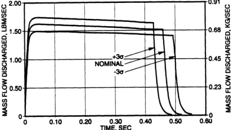
and out of the coolant chamber versus time (Figure 14), are directly analogous to typical automotive airbag gas generator mass flow rate versus time curves for the combustion and discharge chambers (Figure 15). As can be seen, the dynamics of the first one hundred milliseconds are similar enough between the two models to allow for the use of findings from the automotive industry pertaining to inflation and deployment forces to be used for the Mars Pathfinder folding schemes.
The automotive airbag models, however, cease to be similar to Pathfinder's after the first one hundred milliseconds, which is why the information from them can only be used for folding scheme ideas, and not the entire deployment process. Automotive airbags deflate rapidly soon after the half of a second, whereas Pathfinder's airbags remain inflated. Also, the information about deployment loads and the unfurling of material is only marginally useful, because automotive airbags can be folded up without any constraints, while Pathfinder's airbags have complex internal and external hardware that needs to be oriented properly.
o C., w u,
W
0 w I0 -J LL U, U, C., Owt/)U, (0W
a
CO U, -I LOW U, U,) TIME, SECFigure 13. Mass Flow Rate out of the Propellant Chamber versus Time, Pathfinder.
d
W
0 c.) w I -C. 03 0 0.10 0.20 0.30 0.40 0.50 0.60 TIME, SECFigure 14. Mass Flow Rate out of the Coolant Chamber versus Time,
(Courtesy of ILC Dover, Incorporated.)
700 600 500 400 300 200 100 20 40 60 80 O u, 0 -.J Q
U)
CO
Pathfinder. 1200 1050 900 750 600 450 300 100 Time (ms)Figure 15. Mass Flow Rates out of the Combustion Chamber (continuous line) and Discharge Chamber (dotted line), Typical Automotive Airbag Gas Generator Model.
GUIDE TO THIS THESIS
Chapter One of this thesis has introduced the Mars Pathfinder mission and the background areas that were researched to gain knowledge in the areas of gas generators, inflation models, airbag folding methods, and general airbag deployment. Chapter Two will describe the test equipment, the airbag, and the scale model used in the experiments, and Chapter Three explains the operating procedure. The four different folding schemes and trials completed in the experiments are also detailed in Chapter Three. Results of the folding schemes and the different diffusers and deflectors are given in Chapter Four, and Chapters Five and Six discuss the results and summarize the work done, respectively.
Chapter Two: Apparatus
A quarter scale mock-up of one of Mars Pathfinder's four lander petals, the associated airbag subsystem for that petal, and the other necessary test apparatus were fabricated and set up in a testing room at the Jet Propulsion Laboratory.
GENERAL TEST HARDWARE
The general test hardware included two major pieces. A base structure supporting a thirty-two gallon tank, a test bed, and a pipe connecting the tank to the test bed was the first piece, and a Lexan safety shield was the second. Figure 16 below shows a top view of the base structure and the shield. The base structure is pictured horizontally, with all units in inches, while the shield is the vertical I-shaped member. Side and front views follow on the next page in Figures 17 and 18, respectively.
Typical
~--- t
Figure 17. Base Structure and Shield, Side View.
Figure 18. Base Structure and Shield, Front View.
Not pictured in the previous three figures are the inlet hose and the test bed. These are shown in the pictures of the test hardware from the front side toward the rear,
and then vice versa, in Figures 19 and 20, respectively. In the view from the front, a
Figure 19. Test Hardware, View from Front.
Figure 20. Test Hardware, View from Rear.
valve can be seen against the back wall. When open, air was pumped from the source behind the wall through the valve (where the two gauges can be seen) and then through the tubing down into the back side of the gray thirty-two gallon tank. In this same picture, a pipe extends forward from the tank and curves up at a ninety degree elbow.
Half-way between the tank and the point at which the pipe curved up was a butterfly valve. This was used to release tank pressure, thereby inflating the airbag, which was located on the horizontal test bed above the vertical section of pipe that stemmed up from the ninety degree elbow. A flange at the top of the vertical pipe section mated with the forty inch square masonite test bed, which was covered with checkered cloth for a spatial reference while filming from above. A flow orifice plate was used to regulate the mass flow rate into the airbag. It was sandwiched between the pipe flange and the test bed, and cannot be seen in the picture.
MARS PATHFINDER AIRBAG
The airbag, which is shown fully inflated in Figure 21 on the following page, was a quarter scale mock-up of the Mars Pathfinder airbag. The mock-up, though made of different materials than the full scale airbag, was equipped with the full internal and external tendon assemblies and hardpoint attachments to the lander petal. For a scale reference, each square of the checkered pattern is one and a quarter inches square. Figure 22 shows an early version of the airbag that had only three lobes, whereas the current design has six, but the hardware in both designs is essentially the same. The internal and external tendons, which on the mock-up were simply ribbons fixed at their endpoints by grommets, are routed throughout the inside and outside of the airbag in directions that
Figure 21. Quarter Scale Mars Pathfinder Airbag, Fully Inflated.
GAS PUR SYSTEM
Figure 22. Mars Pathfinder Airbag Internal and External Hardware.
provide rigidity and tension when the airbag is loaded from any direction. The six lobe design has four cusp assemblies instead of one (shown as darkened circles in Figure 23 below), placed at the intersections of the six lobes. This new design allows for better cushioning when the lander hits the surface and for more airbag coverage over the lander petals. The quarter scale airbag was thirty-six inches along each side of the equilateral triangle formed when spread out flat on the test bed.
Figure 23. Six Lobe Airbag Design, Top View.
MARS PATHFINDER LANDER PETAL
The quarter scale mock-up lander petal, made of one-eighth inch thick masonite, was fixed to the quarter scale airbag at the hardpoints as shown previously in Figure 22. The petal was representative of any of the four petals on the lander, as they are all
the pipe flange through the four bolt holes shown in the middle area of the petal, and the airbag attached to the petal on the opposite (upper) side at the small holes around it's perimeter. All dimensions in Figure 24 are in inches.
Though the placement of the gas inlet hole shown in this diagram is in the center, the most recent design change in the petal put the inlet in the lower section of the
triangular petal, which is where it was for the filmed inflations included with this document. Because of the nature of the design process at the Jet Propulsion Laboratory,
V
5Figure 24. Quarter Scale Lander Petal, Top and Side Views. r~r
the inlet hole position changed numerous times over this six month project. Consider Figure 24 to be for general illustrative purposes and petal dimensions only, as the inlet hole position currently being considered for the lander petal, which was the one used in
the inflations for this project, was actually closer to the lower bolt hole.
FLOW DIFFUSION AND REDIRECTION
There were two primary variables of interest in this project, one of which was the folding scheme used for a given inflation. The other variable, which was of equal importance, was the method of inflation. The two different methods of inflation used were the diffusion of the airflow entering the airbag inlet hole and the deflection of it.
DIFFUSERS
A swatch of material, either high or low porosity, depending on the desired
inflation duration, was clamped over the diffuser/deflector flange to regulate the air flow into the airbag. The diffuser/deflector flange, which was simply an aluminum tube with lipped edges that accommodated both diffusers and deflectors, bolted directly to the orifice plate. The airflow redirection devices were clamped with a hose clamp to the diffuser/deflector flange. The air flow entered the airbag after traveling first through the orifice plate at the end of the pipe, then through the diffuser/deflector flange, then through whatever flow redirection device was attached to the diffuser/deflector flange. The diffusers, swatches of material with different porosities, are shown in Figure 25. If slow inflation was the objective of a particular trial, low porosity satin was clamped to the diffuser/deflector flange. If rapid inflation was desired, high porosity cotton was used.
Figure 25. Diffusers. Low Porosity (left) and High Porosity (right).
DEFLECTORS
Figure 26 displays a tri-chute deflector and a flow redirection tube. The tri-chute deflector split the air flow in three directions angled one hundred twenty degrees apart. A simple flow redirection sock is pictured in Figure 26. With both of these deflectors, the air flow was not diffused in any manner, and entered the airbag in a direct stream from the vertical pipe through the diffuser/deflector flange
The reasons for the use of each of the different diffusers and deflectors will be detailed in the explanation of the trials. Note that the test bed (the masonite square covered with checkered cloth onto which the mock-up lander petal and airbag are bolted) has been removed from Figures 25 and 26 so that the orifice plate and flow diffusion and redirection devices may be seen clearly.
DATA RECORDING MEDIA
Data recording devices used for the folding schemes and inflations in this thesis include a Polaroid camera, a Sony Handycam video recorder, and a handwritten fold form. Each fold of each of the four folding schemes was video taped as it was being
performed, and a Polaroid shot was taken at the end of each fold. Also used to record folding schemes was a paper form of recording folds that has sections for both verbally and visually explaining how each fold was made and what the resulting geometry was after completing the fold. The inflations for the varying flow inlet conditions and the four different folding schemes were all video taped.
Chapter Three: Procedure
The deliverable of this thesis was a document to ILC Dover, Incorporated
outlining the processes by which four folding schemes were completed and their resulting inflation dynamics. Folding schemes are sets of individual folds, done one at a time, that when done in the proper order result in a certain folded geometry. Deployment dynamics,
which are basically the characteristics of an inflation (such as "smooth," "even," or "lopsided") that can be used to describe or define it, are dictated by the original folded geometry of the airbag. The packaged geometry of an airbag, when paired with a
particular choice of air flow diffusion or redirection, entirely determines the deployment dynamics.
In this set of experiments, the folding process and the particular order in which the folds were made were of utmost importance, while diffuser and deflector design were of secondary importance, to the Jet Propulsion Laboratory and ILC Dover, Incorporated. ILC Dover, Incorporated will be designing, fabricating, and packaging the Mars
Pathfinder Airbag Subsystem, and will be using the quarter scale experiments described in this thesis to help direct their efforts to produce an optimal folding scheme and optimal
gas inlet conditions. Because the actual folding process and the particular folds that comprise each folding scheme were both of primary interest, the conveyance of not just the results of the inflations done with the quarter scale test setup, but also the operating procedures leading up to those results, was the main objective of this project.
OPERATING PROCEDURE
PREPARATION
For each individual step of a folding scheme the fold was video taped as it was being made; a Polaroid picture of the fold was taken after it was performed; and then the resultant shape of the airbag was recorded on a fold form (which will be described below). For example, the first step of each of the four folding schemes was always to vacuum all of the air out of the airbag. Then the "hand hole," a small slit in the side of one of the airbag's lobes through which the internal airbag hardware could be accessed, was taped shut. Finally, the airbag was spread out into a flat, triangular shape on the test bed.
This preparatory step of each scheme was recorded as Step A of whichever folding scheme was being performed. The individual folds were lettered, so the second step of every scheme was labeled Step B of that scheme, the third C, and so on. The folding schemes, which were specific collections of steps performed in a certain order, were numbered one through four. Each of the four folding schemes was paired up with each of the methods of air flow modification described in the previous chapter to produce different trials, all of which were numbered. For example, Folding Scheme One paired with the low porosity diffuser was Trial One, while Folding Scheme Two paired with that same method of air diffusion was a separate numbered trial -- Trial Two, in this case.
BEFORE EACH FOLD
Because of the importance of reproducibility of these folding schemes to ILC Dover, Incorporated, a fold form was devised so that the series of folds comprising each
folding scheme could be repeated on the full scale airbag to produce the same packaged geometry (to achieve the same inflation dynamics) as that which was achieved with the quarter scale mockup. Each fold was described in detail, with explicit directions as to how to proceed before and after that particular fold. An example of a fold form for Step A of Scheme Two is shown below in Figure 27.
Folding Scheme # 02 0.
The top half of the fold form describes both verbally and visually how the fold was to be made. In this case, the operation being performed was not exactly a fold, but this first step's simplicity allows the four areas of the fold form and the information they contain to be displayed in a format that is easy to understand.
The left half of the upper portion of the fold form describes verbally how to perform the upcoming fold, and the right describes it visually. In the visual sketch, bold lines indicate the current perimeter of the airbag, while dotted indicate where the
perimeter will lie once the fold has been made. The dark, filled-in circles indicate "grab
points" -- suggested places to hold the airbag material as the fold is being made -- and open circles indicate where the material at the grab points should be after the fold is complete. Arrows show the motion or direction that one moves the grab points to achieve that particular fold. After filling out the upper half of the fold form, the fold was then carried out while being video taped.
AFTER EACH FOLD
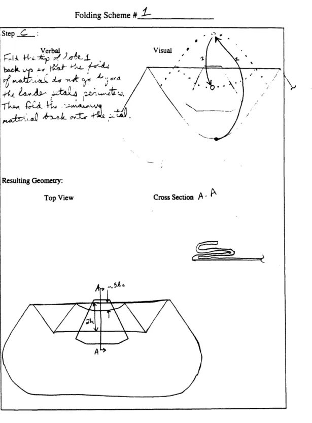
A Polaroid picture was taken after the fold was done on the airbag. The lower half of the fold form, which shows both a top view sketch and a cross section of the airbag after the fold described in the upper half of the form has been made, is then filled out. To allow for easier reproduction of these folding schemes with the ILC Dover, Incorporated full scale airbags, all dimensions that characterized a fold were measured in characteristic lengths, which, in these folding schemes, was chosen arbitrarily to be the distance between the two hardpoints on the upper edge of the lander petal. This distance on the quarter scale mock-up was 3.75 inches.
On the first fold form of each scheme the airbag lobes were numbered so that they could be referred to in folding instructions. Because the folding schemes got more complex with each fold made, drawing all previous folds in the sketch cluttered the view from the top and proved to be more of a hindrance than a help, so the airbag was treated as being opaque, and only the most recent fold and the perimeters of that fold as seen from above were drawn.
INFLATION
After each folding scheme had been performed and documented with the fold forms, Polaroid pictures, and video tape, its inflation was then filmed. For each inflation the thirty-two gallon tank was pressurized up to twenty-two pounds per square inch. This *was found to be just enough air to unfurl all the folds and allow the airbag to assume its full shape, but not so much air that excessive forces were placed on the tendons or that the bag was damaged in any way. The butterfly valve in the pipe connecting the tank to the airbag was pushed to an open position allowing the tank to release the pressurized air, which then inflated the airbag.
FOLDING SCHEMES
FOLDING SCHEME ONE
Scheme One was intended to be an example of a "bad" scheme. There were several folds that entirely covered other folds, which caused unnecessarily large
deployment loads. Large deployment loads are responsible for not only violent motions when folds of a scheme unfurl, but also damage to the airbag when the forces on the inner surface of the airbag exceed those required to unfurl a fold. Each step of Folding Scheme
One had very large portions of material left overhanging the lander petal edges, which means that with each successive fold unfurled, the internal forces required to unfurl the flaps of material were very large compared to other types of folds used in later schemes. The larger the flap of material that extends beyond the fold line, the more difficult it is to unfurl and inflate for the blast of air trying to unfold it.
Folding Scheme One is described both verbally and visually in the fold forms that follow in Figure 28. The pictures that were taken after each fold are shown in Figure 29. Only pictures of Steps A through G are included because the pictures beyond that point do not convey enough information about the folds. If attempting to recreate this folding
scheme, the fold forms and the video tape should be used. The still pictures beyond the first few folds are of marginal value because of the added complexity that the folding scheme takes on with each successive fold. The time-stamped video tape included with this thesis shows the entire succession of folds that comprise Folding Scheme One. The segment begins at about eight and a half minutes into the tape and lasts for roughly five minutes.
Folding Scheme #
_-Figure 28. Fold Forms for Folding Scheme One. Step A.
Folding Scheme #
J-Figure 28. Fold Forms for Folding Scheme One, Continued. Step B.
Folding Scheme #_ _ _
Figure 28. Fold Forms for Folding Scheme One, Continued. Step C.
Folding Scheme # 1 Step n "
Verbal
/
Resulting Geometry:
Top View Cross Section
A
AFigure 28. Fold Forms for Folding Scheme One, Continued. Step D. Vilani --- ? -L , ~~uZ ;;p"~'L~~ ii
7Mb
Folding Scheme # Step .: Visual Verbal 4 - i. .4 /-v V. .jii )1AiiA Resulting Geometry:
Top View Cross Section
A A
Figure 28. Fold Forms for Folding Scheme One, Continued. Step E.
0*
Folding Scheme # Step . Verbal , '.1-: -K 1 ,, ' ,.- _-a t. i t/.~-ra " iLT2 A . /• I>...,• ' - - • (. Visual Resulting Geometry:
Top View Cross Section A -
A
.A~a •ý c ':C
-l''l -Žc~a
Figure 28. Fold Forms for Folding Scheme One, Continued. Step F.
po'ý A-AA
~-· ,
4-r-Folding Scheme #_ _ _
Figure 28. Fold Forms for Folding Scheme One, Continued. Step G.
Folding Scheme #_ _ Verbal I-4A .it 'i Visual Resulting Geometry:
Top View Cross Section
Figure 28. Fold Forms for Folding Scheme One, Continued. Step H.
Folding Scheme # Step : Verbal L' 14I ) vJ 2 cp · · ~' r ~ KQ P
P
,J: aci4L Visual O Resulting Geometry:Top View Cross Section
Figure 28. Fold Forms for Folding Scheme One, Continued. Step I.
Folding Scheme #_ Step • Verbal 4c~a4rz~i·~·;h·h·'~
K
ft-"
~,2·.~3~A LCc~ ,ii. g~L~~ Resulting Geometry: Top View Visual Cross Section-Figure 28. Fold Forms for Folding Scheme One, Continued. Step J.
Folding Scheme # Step : Verbal ,- .4 3
AL
-cn. J4A-4 tl Resulting Geometry: Top View Visual Cross SectionFigure 28. Fold Forms for Folding Scheme One, Continued. Step K.
Figure 29. Pictures of the Steps of Folding Scheme One. Step A (below).
-··r,
i~k
,,
:~ri·J
~
rd~::-jglp.p2q s~ ai:Figure 29. Pictures of the Steps of Folding Scheme One, Continued. Steps B (above) and C (below).
Figure 29. Pictures of the Steps of Folding Scheme One, Continued. Steps D (above) and E (below).
Figure 29. Pictures of the Steps of Folding Scheme One, Continued. Steps F (above) and G (below).
FOLDING SCHEME TWO
Scheme Two is a design that could best be described as continuous helical accordion fold. It begins at the base of the airbag making "S" shaped folds that spiral clockwise and upward in a helical pattern. After the first fold was made on the lower side of the lander petal (Step B), the same fold was performed along the petal edge to the left of the base. Then the same "S" shaped accordion fold was done along the petal edge to the left of that, and so on, until the material leading up to the top of the airbag was completely folded up within the bounds of the lander petal edges, with the exception of the three flaps of material overhanging the edges. The fold forms for Folding Scheme Two are included in Figure 30 and pictures of the first few steps can be found in Figure 31. The five minute video segment showing the steps of Folding Scheme Two can be seen on the video tape after the fifteen minute marker.
Folding Scheme # , -O
Figure 30. Fold Forms for Folding Scheme Two. Step A.
Folding Scheme # c
Figure 30. Fold Forms for Folding Scheme Two, Continued. Step B.
Folding Scheme #
`-Step
:-Visual Verbal
Resulting Geometry:
Top View
Cross Section
-
4
Figure 30. Fold Forms for Folding Scheme Two, Continued. Step C.
Folding Scheme # __ Step "T Verbal 7 0,
I~c
b ·
~~~ -Visual A--· Resulting Geometry:Top View Cross Section A A
Figure 30. Fold Forms for Folding Scheme Two, Continued. Step D.
Folding Scheme #
Step E :.
Verbal
P-- " · -J r U i
SC~L:, •t~ l-fr
-kV Al-· L, -?id ~'&*:J (-'N
;· 5
Visual
/s
Resulting Geometry:
Top View Cross Section A '-/
Figure 30. Fold Forms for Folding Scheme Two, Continued. Step E.
Folding Scheme # W
Step :
Verbal Visual
,4,,.;_2. _ " .. , h -. •
Resulting Geometry:
Top View Cross Section ý
Figure 30. Fold Forms for Folding Scheme Two, Continued. Step F.
Folding Scheme # O2 Verbal Resulting Geometry: Top View Visual Cross Section
Figure 30. Fold Forms for Folding Scheme Two, Continued.
Folding Scheme # . Step : Verbal ~LL~4 'JWf& (If~#A Resulting Geometry: Top View Visual Cross Section
Figure 30. Fold Forms for Folding Scheme Two, Continued. Step H.
Figure 31. Pictures of the Steps of Folding Scheme Two. Step A.
~31~~ r~ agr::
Figure 31. Pictures of the Steps of Folding Scheme Two, Continued. Steps B (above) and C (below).
Figure 31. Pictures of the Steps of Folding Scheme Two, Continued. Steps D (above) and E (below).
W 9
Figure 31. Pictures of the Steps of Folding Scheme Two, Continued. Steps F (above) and G (below).
FOLDING SCHEME THREE
Scheme Three was an attempt to get rid of the last three flaps of material left overhanging the lander petal edges after most of the material was folding inward. Both Scheme One and Scheme Two had these leftover flaps, and the unfolding of Scheme Two would have been entirely smooth if those three flaps could have been eliminated. The lobes of the airbag that made up the majority of the material left overhanging the petal edges (lobes one, three, and five) were folded inward on top of themselves first (as opposed to Schemes One and Two where they were folded inward last) and then the remaining lobes were folded in toward their respective petal edges in a stacked accordion pattern. Fold forms and pictures for Scheme Three are shown in Figures 32 and 33, respectively, and the video taped segment showing the steps of Folding Scheme Three begins at twenty-six minutes.
Folding Scheme # 3
Figure 32. Fold Forms for Folding Scheme Three. Step A.
Folding Scheme # ? Step i: Verbal I J i, ~ 1 • ,/ ~~&LL~ K ýZ~'
f&ý
C4 744 Resulting Geometry:Top View Cross Section A -
A
A
7-4
Figure 32. Fold Forms for Folding Scheme Three, Continued.
Folding Scheme #
3
Step : Verbal Resulting Geometry: Resulting Geometry: Top View VisualCross Section
A
-A
Figure 32. Fold Forms for Folding Scheme Three, Continued. Step C.
Folding Scheme # 3 Step L) Verbal Resulting Geometry: Top View Visual Cross Section A -A
Figure 32. Fold Forms for Folding Scheme Three, Continued. Step D. 74 V
)
tl i i~:r·L4~ .k'e ~eFolding Scheme # Step t : Verbal F-; ~, ~ -g~.;~ ~.·-)· ;_&~A,' ~,c' 2l iTL~4L Resulting Geometry: Top View ). > Cross Section A
A
Figure 32. Fold Forms for Folding Scheme Three, Continued. Step E.
Folding Scheme # Lep : Verbal f- "- , ) ~- -Resulting Geometry:
Top View Cross Section A A
Figure 32. Fold Forms for Folding Scheme Three, Continued. Step F.
Visual
A'-(
Folding Scheme #
Step :
Verbal ,•t Visual
r
Resulting Geometry:
Top View Cross
Figure 32. Fold Forms for Folding Scheme Three, Continued.
Step G. ~ ·~rr
-p 1_,6
Folding Scheme # -Step H1 Verbal
IIcý
R)
Resulting Geometry:Top View Cross Section - I
Figure 32. Fold Forms for Folding Scheme Three, Continued. Step H.
78
Visual
I--
t~i
ý i 4-4LJ
Folding Scheme # Verbal Resulting Geometry: Top View Visual .. ~ II Cross Section ý ý Iz~i g-i.iic
Figure 32. Fold Forms for Folding Scheme Three,
Step I.
Continued.
oldaing Scneme #_ _ _ Step 7 : Verbal <L •1 Visual Resulting Geometry:
Top View Cross Section
Figure 32. Fold Forms for Folding Scheme Three, Continued.
Step J.
r~l ln cnem
Folding Scheme # Step : Verbj
}
/<~2r riP~ i~ .. Let I, *0 Visual • ,, ,,. Resulting Geometry:Top View Cross Section
Figure 32. Fold Forms for Folding Scheme Three, Continued. Step K.
Figure 33. Pictures of the Steps of Folding Scheme Three. Step A.
mm - - -w
-Figure 33. Pictures of the Steps of Folding Scheme Three, Continued. Steps B (above) and C (below).
U ~
Figure 33. Pictures of the Steps of Folding Scheme Three, Continued. Steps D (above) and E (below).
,rilE-a -0 A -W.M-
Figure 33. Pictures of the Steps of Folding Scheme Three, Continued. Steps F (above) and G (below).
4~
u*-~
b~~
Figure 33. Pictures of the Steps of Folding Scheme Three, Continued. Steps H (above) and I (below).
FOLDING SCHEME FOUR
Scheme Four was the design most recently proposed for Mars Pathfinder's airbag subsystem folding scheme by ILC Dover, Incorporated. Fold forms have not been included because of its similarity to JPL's Folding Scheme Two. The only notable differences were the order in which the folds were performed. As seen in Figure 34, the "S" folds are stacked vertically along one edge of the petal, proceeding from the bottom fold up to the top along each edge. The vertical stack of three accordion folds is
completed along each petal edge before moving to the next edge and beginning another vertical stack along the second edge, as opposed to Folding Scheme Two in which the first layer of each of the three stacks was folded all the way around the petal, then the second layer, and finally the third. Folding Scheme Four built the folds in the airbag up each side of the triangular petal, whereas the design of Folding Scheme Two wrapped the airbag material in a helical pattern from the base up toward the top.
Figure 34. Pictures of the Steps of Folding Scheme Four. Step A.
-~~~
mC2
Figure 34. Pictures of the Steps of Folding Scheme Four, Continued. Steps B (above) and C (below).
V
r p-·nc~c~
Figure 34. Pictures of the Steps of Folding Scheme Four, Continued. Steps D (above) and E (below).
Pictures of the Steps of Steps F (below)
Folding Scheme Four, Continued. and G (above).
TRIALS
TRIALS ONE THROUGH SIX
A trial consisted of one of the four folding schemes paired with one of the two available diffusers or two deflectors in an inflation. Trials One through Three consisted of the first three folding schemes described in the previous section inflated with the low porosity diffuser (Figure 25, Chapter Two) and with a three-sixteenths inch orifice plate. Trials Four through Six had all the same conditions as Trials One through Three, but were inflated with a half-inch orifice instead. Trials One through Three can be seen on the video tape within the first eight and a half minutes. Trials Four through Six follow on the tape up to the thirty-eight minute marker, each one following the folding of each of the three folding schemes.
TRIALS SEVEN THROUGH TEN
Trials Seven through Ten, which involved all four of the folding schemes paired with the high porosity diffuser, are the ones highlighted in pictures in the results section of Chapter Four, because their inflation times were shorter than the times associated with the low porosity diffuser of the first six trials. These rapid inflations were much better indicators than the previous trials of the true inflation dynamics that will be experienced with the full scale airbags. The inflation dynamics and times of the quarter scale mock-up with the high porosity diffuser installed were closer to those expected of the full-scale
airbag subsystem's than the low porosity trials, so the remainder of the trials used the high porosity diffuser.
Another reason for the use of the high porosity diffuser instead of the low porosity one used in the first six trials was because it provided a simple baseline for the unfurling of each folding scheme without any added factors, such as flow redirection, the spring rate of the material as it unfolds, and diffusing the mass flow so much that the value of the inflation data is questionable. The inflation of Trials Seven through Nine can be viewed on the video tape within the forty to forty-five minute range, and Trial Ten begins
at around fifty minutes.
TRIALS ELEVEN THROUGH FOURTEEN
Because of findings from the first few inflations, a tri-chute deflector was designed, fabricated, and tested without the airbag. No inflation data was recorded because the deflector was later blown apart during its first inflation with the airbag. (Details follow in the Results chapter.) Another deflector was fabricated, this one being a simple flow redirection device (Figure 25) that effectively moved the gas inlet hole closer to the center of the lander petal. It routed the air from the lower section of the petal toward the center with a tube in hopes of achieving a more evenly distributed gas flow for smoother deployment. Trials Eleven through Fourteen, which take up the remainder of the video tape, were Folding Schemes One through Four paired up with the flow redirection sock.