Designing Decision and Collaboration
Support Technology for
Operators in Multi-UAV Operations Teams
F.M. Almirao
F.B. da Silva
S.D. Scott
M.L. Cummings
Massachusetts Institute of Technology*
Prepared For Boeing, Phantom Works
HAL2007-02
July 2007
*MIT Department of Aeronautics and Astronautics, Cambridge, MA 02139
2
Table of Contents
1 Introduction………..………....3
2 Representative Time-Sensitive Team Task: UAV Ground Force Protection ... 3
3 Cognitive Task Analysis ... 4
3.1 Scenario Task Overview ... 5
3.2 Event Flow Diagram ... 7
3.3 Situation Awareness Requirements ... 8
3.4 Decision Ladders and Display Requirements ... 10
3.5 Summary of Requirements Generated from the CTA ... 15
3.6 UAV Operator Display Designs ... 19
3.6.1 Map Display... 20
3.6.2 Communications Display... 21
3.6.3 Tasking Display ... 22
4 Conclusion and Future Work ... 24
5 References... 24
1 Introduction
Effective team collaboration and timely decision-making significantly influence the outcome of time-sensitive military operations. The increasing complexity introduced by the recent move towards network centric operations (NCO) in U.S. military operations provides additional challenges for efficient decision-making. Future operations will include co-located and distributed teams composed of operators from difference services, often at different global locations. Military operations which require extremely quick decisions, such as operations dealing with time-sensitive targets (TST) like improvised explosive devices (IEDs), are particularly challenging in NCO teaming environments. Operators in TST environments not only have to manage overwhelming amounts of target-related information, but also have the overhead of communicating and coordinating with co-located and distributed team members. Given the increasing trend for modern hostile forces to employ unconventional weapons such as IEDs and suicide bombs, the success of TST operations are becoming critical to current and future military operations. Providing TST teams with effective tools for communicating and coordinating their efforts is key to enabling their success.
Despite advances in collaborative technologies and extensive research in military teams, decision-making and collaborative activities continue to be time-consuming and often ineffective during time-critical operations. This project aims to improve teamwork in TST operations by investigating possible supporting technologies. In particular, the project is focused on facilitating coordination between remote team members and co-located operators who are required to continuously attend to critical information on their individual workstations. It is often difficult for these operators to gather key information regarding their teammates’ activities. To address this issue, the project is exploring ways to improve activity awareness among networked TST operators, a design approach focused on improving planning and coordination in collaborative activities through intelligent sharing of group activity information (Carroll et al., 2003; Carroll et al., 2006).
In order to develop requirements for activity awareness displays that support networked TST operations, a cognitive task analysis (CTA) was performed on a representative time-sensitive team task scenario. This report details this CTA, along with an initial set of operator displays that were designed to satisfy the resulting requirements. To set the context for this work, the representative task scenario is first described. This is followed by the details of the requirement generation process and a description of the resulting design of the team operators’ decision-support displays.
2 Representative Time-Sensitive Team Task: UAV Ground Force Protection
In order to better understand how to develop display technologies that assist TST operations teams, a representative time-sensitive team task scenario was developed. The task scenario involves a team of operators working together to secure a large geographic area (the team’s area of interest (AOI)) to ensure the safe passage of an important political convoy that will be traveling through the area in the near future. During the task, the team is required to surveil the area for potential threats. Once hostile targets are identified, the team must coordinate with an external strike team to engage these hostile contacts before they are within weapons range of the convoy. The team is required to monitor incoming intelligence reports in order to extract
4
information relating to their AOI and potentially communicate with other teams as necessary to clarify intelligence reports.
In order to secure the AOI, the team is required to utilize a number of semi-autonomous unmanned aerial vehicles (UAVs). Various team members are required to monitor the progress of these UAVs as they provide surveillance of the large AOI, and to reroute the UAVs from their original surveillance course, as necessary to secure the area. The team may also be required to coordinate with other teams to utilize assets outside of their immediate control to help secure the AOI.
The TST team consists of three UAV operators, each responsible for controlling multiple UAVs and one mission commander overseeing the team’s mission progress. In particular, the UAV operators are each responsible for supervising the progress of several UAVs surveilling the AOI, confirming potential targets identified by the UAVs’ onboard automatic target recognition systems, and coordinating with a strike team operating in the area to destroy confirmed targets. When appropriate, the UAV operators are also responsible for UAV rerouting within their respective AOIs or to other AOIs (where a UAV would be handed off to the operator responsible for that AOI). Such rerouting would involve negotiating time constraints and availability across stakeholders, and making sure that the plan modifications do not violate any operational constraints.
The mission commander is responsible for ensuring the safety of the convoy and for managing the workload of the UAV operators on his or her team throughout the team’s mission. To achieve these mission objectives, the mission commander can make several types of strategic decisions: request the convoy hold its current position if its intended path is not deemed safe for passage, request supplementary surveillance data from a nearby joint surveillance and target attack radar system (JSTARS), or request the re-tasking of one of the team’s UAV assets to a different sub-AOI (requiring the handoff of the UAV asset between operators).
While there are many collaborative components to this UAV ground force protection task, this phase of the project will focus on the decision-making and performance of the multi-UAV operators managing the progress of UAVs and re-tasking their UAVs when necessary. This phase of the project extends previous work that focused on developing technological support for team supervision (i.e., the mission commander) in this task scenario (Scott et al., 2006; Scott et al., 2007).
3 Cognitive Task Analysis
This project aims to understand how to support teamwork engaged in TST operators involving anticipated UAV platforms and capabilities. Thus, the representative team task involves a futuristic battlefield scenario. To develop requirements for this futuristic task environment, the Hybrid Cognitive Task Analysis (CTA) method (Nehme et al., 2006) was used since this method was specifically designed to assist the development of revolutionary systems. The traditional CTA approach requires subject matter experts, documentation, and previous implementations to derive design requirements. However, these resources are unavailable in futuristic systems with no predecessors. The Hybrid CTA takes these constraints into account and presents a structural process to aid in the generation of display requirements via functional and information requirements.
The Hybrid CTA compensates for the lack of subject matter experts, previous implementations and documentation by modifying the task decomposition phase of a traditional CTA into a five-step process:
1. generating a scenario task overview, 2. generating an event flow diagram,
3. generating situation awareness requirements, 4. creating decision ladders for critical decisions, and 5. generating a requirements summary table.
The process first establishes a high-level mission outline and ultimately allows the analyst to extract information and display requirements from the requirements summary table.
A scenario task overview serves as the foundation of the Hybrid CTA (henceforth referred to as the CTA). For this project, the UAV Ground Force Protection task described above will serve as the scenario task overview. Moreover, for this particular phase of the project, only the team operators’ role in the UAV Ground Force Protection task will be considered for this CTA (the supervisor’s CTA is the subject of another related technical report, HAL2007-03, currently under review at Boeing).
3.1 Scenario Task Overview
In this step of the CTA, the mission goal is first established and then divided into phases based on high-level changes in operator tasking. A hierarchy is created by creating sub-goals within each phase, and then detailing the sub-tasks for each of these sub-goals, finally leading to individual sub-tasks. There are three main phases associated with the UAV ground force protection task: mission planning, mission execution, and mission recovery. This project focuses on developing support for the mission execution (which may involve some mission replanning). It is assumed that the tasks of the formal mission planning have been completed prior to our task scenario.
Table 1 lists the tasks that we assume have been completed during that mission planning phase.
These tasks will generate information that feeds the next phase, the mission execution phase. Within the UAV ground force protection task, there are five basic phase goals and event types: Launch UAVs Phase, ISR (e.g., scouting the area in search of potential enemies), target detection (e.g., confirming target identified by the UAVs’ onboard target identification systems), target schedule (e.g., receiving acknowledgement from the external strike team that a detected target has been scheduled to be destroyed), and UAV reroute/reassigned (e.g., planning new route for UAV). There are also off-nominal events that the UAV team may need to handle while executing the mission scenario: A UAV could be destroyed (or become incapacitated due to equipment malfunction), and the UAV team could lose their communications link to one or more of their external contacts (i.e., the convoy, the strike team, or JSTARS).
Table 1 details the expected or possible tasks and subtasks of the UAV team, and in particular of
6
Finally once the mission has been executed, the UAV team will need to recover the deployed UAV assets. This mission recovery phase may involve recalling the UAVs to a nearby base or re-tasking them to another mission. This project will only nominally consider this phase of the mission, as it is not our current focus.
Table 1. Operator CTA Task Scenario Overview
Issues to be resolved in this phase: Helpful information for resolving these issues:
Mission Planning
– Each operator will have a pre-defined area under his/her responsibility – Each operator will have a pre-defined # of
UAVs under his/her responsibility – Initial search area for Search UAVs will
be determined
– Initial mission route for each UAV will be determined (Choose a pre-defined initial
route for each UAV) – Plan safety route
– Visual indication of area under his/her responsibility; – Mission clock;
– UAV surveillance speed;
– Engaged time (operator target confirmation time, communication time with strike team, mCDR and UAVs, strike
team schedule timing);
– Average time that target recognition will take; – Visual indication of search areas/ tactical map;
– Expected convoy arrival time, path;
– Suggestions of possible UAV routes/ Visual indication; – Ideal range of UAVs for accurate target automatic target
recognition (ATR);
– UAVs endurance/health status (fuel, physical conditions) Phase Goals Phase Breakdown
Launch UAVs Phase – Launch Search UAVs
ISR
– UAVOP monitors AOI while UAVs search for potential threats
– Monitoring health status
Target Detection – UAV's onboard ATR sends a potential target alert to the controlling UAVOP – UAVOP examines ATR to confirm or refute target ID – If it's a target: Process target ID information/ classification
– Possibility to request mCDR's help
Target Schedules
– Check strike team and mCDR's availability – Submit target information details to strike team (high or low
priority, target classification, and position) – Send message of target confirmation to mCDR
– UAV goes back to searching task – Feedback of target scheduling from strike team Mission
Execution (Basic phases/events)
UAV reroute/reassigned
– mCDR request for a UAV task modification – Communicate intentions to mCDR
– Perform route modifications – Confirm the modification
UAV destroyed – All operators and mCDR are notified about the UAV loss – Target lost added to strike team schedule – Notification whether mCDR decides to reassign another UAV
from another operator's AOI Mission
Execution (Possible
off-nominal events) UAV malfunction – The operator is notified about malfunction – Recall UAV to base if necessary
– Alert mCDR of modifications Mission
Recovery
Once the mission Execution Phase is completed or is aborted, UAVs are recalled to base or re-tasked to another mission
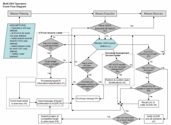
3.2 Event Flow Diagram
Next, the event flow diagram stems from the tasks and subtasks detailed in the scenario task overview. The event flow diagram sketches the mission execution phase into sequential events, and lists mission planning assumptions. Most importantly, it demonstrates the dependency between events as well as temporal constraints. Three basic event types are used: loops (iterative events that occur until another predetermined event arises), decisions (an event requiring knowledge-based input from an operator), and processes (a task requiring some human-computer interaction).
Figure 1 depicts the event flow diagram constructed from the scenario task overview. The gray rectangles at the top show the three main mission phases: mission planning, mission execution, and mission recovery. Below the mission planning phase is a parallelogram listing the tasks which are assumed to be completed prior to the mission execution phase (our primary concern): each UAV operator is given a pre-defined area of surveillance (their AOI), the number of UAVs assigned to AOI is already defined and UAV areas, search routes and safety route are also already defined.
In the event loop diagram, diamonds depict decisions, hexagons represent loops, and rectangles depict processes involving human-computer interaction. Each decision results in a yes or no answer, which leads to another event. Dotted boxes indicate decisions and related processes that were deemed complex enough to expand into decision ladders. These decision ladders, described in Section 3.4, attempt to emulate the potential cognitive and human-computer interaction activities involved with a particular decision-making process.
In the case of the multi-UAV operators, the main mission execution decision (D1, for Decision #1) establishes if the UAVs from that AOI have executed all tasks. If the UAVs have executed all tasks, the mission proceeds to the third and final phase, mission recovery. Otherwise, the operator enters a monitor UAV/communication status loop (L1, for Loop #1). Monitoring the UAV/communication status consists of observing the status of the UAVs and the communication status with other team members.
If any UAV from an AOI finds a potential threat (D2), the operator needs to decide whether the imagery sent by the UAV contains a target or not (D3). If the image(s) contain a target, the operator classifies this target (P1 for Process #1), submits target details to the strike team (P2), and sends a target confirmation to the mission commander (P3). The operator may also need to re-task a UAV. This activity may be activated by a strict request from the mission commander (D6), or also if a UAV is not functioning normally (D7). In case of a malfunction or if one of the operator’s UAV has been destroyed (D8), the operator needs to notify mission commander and the other operators about it (P7). If the operator determines that UAV was shot down by a target (D10), they will submit the target details to strike team (P8). In the meantime, the operator must be aware of possible communication losses, and when communication links become reestablished (D4) in order to assure that messages are sent and received appropriately.
8
Figure 1. CTA Event Flow Diagram for the UAV Ground Force Protection Scenario
3.3 Situation Awareness Requirements
The third step in the Hybrid CTA generates situation awareness (SA) requirements based on the temporal constraints of the event flow diagram for each phase and subtasks in the scenario task overview. Each requirement is divided into the following levels: perception, comprehension, and projection, which represent the essential mental processing levels needed to gain situation awareness (Endsley, 1995).Table 2 details the SA requirements for the nominal and off-nominal events which may occur during the mission execution phase of the UAV ground force protection task. The SA requirements listed in this table focus on the information that the UAV team, and in particular the multi-UAV operators, may need to perceive and comprehend the current state of the UAV status. These operators also need SA about the team’s communication status and possible predictions of future states throughout the tasks within each mission event (as listed in the Scenario Task Overview, see
Table 2. Operator CTA Situation Awareness Requirements
Phases/Events Level 1 (Perception) Level 2 (Comprehension) Level 3 (Projection)
Launch UAVs
- Visual indication of operator's AOI (D1, L1, P5)
- Visual indication of each UAV route (when requested) (D1, L1, P5, D9)
- Ability to visualize possible UAV routes (D1, L1, P5)
- Visual indication of current UAV route in geo-spatial context (D1, L1, P5, D8, D9)
ISR
Visual indication of:
- Geo-spatial boundaries (D1, L1, D2, P1, P8, P5, D6, D8, D9) - Tactical map (D1, L1, D2, P1,
P5, D7, D8, D9)
- Locations of all UAVs assigned to each operator's area (D1, L1, D2, P1, P5, D8, D9, P8) - Locations of all UAVs
reassigned to each operator's area (D1, L1, D2, D6, P5, D8, D9)
- UAVs’ current activities (searching, loitering, down) (D1, L1, D2, P1, P5, D7, D8) - Communication link status with
UAVs (D1, L1, D2, P1, D4, P5, D6, D7, D8, P6)
- UAVs’ health status (D1, L1, D2, P5, D7, D8, D9)
- Limitations of camera angle view (P1)
- Mission Time (D1, L1)
- Error message/alert clarification (P1, P2, P3, P4, P5, P6, P7,P8, D5)
- UAVs’ monitoring performance (visual indication on tactical map) (D1, L1, D2, P1, P5, D7, D8, D9)
- Communication chat with mCDR (if needing help) (D3, P1, P3, D4, D6, P5, P6, P7) - Position of found targets should
be displayed on tactical map (D1, L1)
- Surveilled & unsurveilled area displayed on tactical map (D1, L1, P5, D9)
- Communication link status (D1, L1, P1, P2, P3, P8, D4, P6, P7) - UAVs limitations (D1, L1, D2, P1,
P5, D7, D9) - Uncertainties
- Strike Team limitations (P2, P8) - UAVs’ expected health status
(D1, L1, P5, D9)
- Area Constraints (no fly zone, current threats, etc) (D1, L1) - Estimated time for the UAV to
start the safety route in case of lost communication with operators (D1, L1)
- Indicate areas in AOI known to cause communication connection losses (D1, L1, P1, P5, D9, P6, D10)
Potential Threat/Target
Detection
- Alert of potential threat detection from UAV (D2, D10)
- Time of potential threat discovery (D2, D10) - Indicate which UAV detected
potential threat (D2, P1) - Indicate potential threat position
(P1, P8)
- Indicate UAV camera capabilities (D3, P1) - Indicate camera angle and
range during image capture (D3, P1)
- Indicate possible match for the threat classification (D3, P1) - Match confidence (D3, P1) - Visual indication of convoy’s
current position (P1) - Re-alert operator if he/she is
taking too long to start potential threat classification (L1) - Communication link status with
the UAVs (L1, D2, D3, D4, P1, D5, P4)
- Show image of potential threat (D3)
- Show options for potential threat classification (e.g.: vehicle, headquarters, strategic, not a target) (P1)
- Ability to request for an updated image from UAV (D3, P1) - Elapsed time since the potential
target was detected (L1) - Ability to request for mCDR to
help with threat classification (D3, P1, D4, D5, P4) - Ability to share threat
classification info with mCDR (and others) (D3, P1)
- Show mCDR’s (or other Ops or any other local authority) threat classification (D3, P1) - Ability to compare ATR image
received with others images (database) (D3, P1)
- Show operator classification for the threat (D3, P1, P2, P3)
- Estimated distance range of target to convoy (P8, P1, P2) - Estimated priority of target with
respect to mission goals (P1) (High, medium, low priority) - Indicate the target’s weapons
range on tactical map (L1)
Target Schedule
- Communication status with mCDR and with strike team (D3, P1, P2, P3, P8, D4, D5, P4)
- Target ID information (P2, P8)
- Schedule of known target strikes (L1, D4, D5, P4)
- Expected availability of strike team in the context of mission activities (D4, D5, P4)
10
Table 2. Operator CTA Situation Awareness Requirements (cont’d)
Phases/Events Level 1 (Perception) Level 2 (Comprehension) Level 3 (Projection)
UAV reroute/ reassignment
- Alert when mCDR requests a UAV reroute/reassignment (D5, D6)
- Indicate if UAV has been destroyed or reassigned or JSTARS was requested (D7, P3,D8, D9, D6, P5) - UAVs’ health and
communication status (D6, D7, D8)
- UAVs’ current routes, location & activities (L1, P3, D6, D8,P5, D7, D9,D2)
- Handoff operator identity & activities (D6, P5)
- Visual indication of surveilled & unsurveilled area (L1, D1, P5)
- Convoy position (mission goal) (P5)
- Convoy route (D1, L1, P5) - Ability to browse
pre-programmed routes options (based on number of UAVs in AOI & convoy location) (P5) - Ability to make a manual route
adjustment on the pre-programmed route and save solution (P5)
- Ability to request assistance (P5)
- Indication of route modifications (P5, L1)
- Indication of UAV following this new route (L1)
- Ability to compare possible route options ("what if") (P5)
- Expected time to surveil critical area (P5)
- Expected mission time for each UAV (D1, L1, P5)
- Expected time of arrival of UAV in reassigned area/location (P5, D1, L1)
- Time requirements of possible new UAV routes in relation to mission time &/or convoy route (P5)
- Operator constraints (if applicable) (P5)
UAV destroyed
- Alert of target attack (D7, D8, D10)
- UAV ID (D8)
- Time UAV was attacked (D8) - Position of UAV (D8)
- Indication of whether UAV was destroyed by an unknown or known target (D7, D8, D10)
- Further intelligence about target that attacked the UAV (D10, P8) - Whether any UAVs are available
for reassignment (D6)
UAV malfunction
Alert operator if (D7):
- Fuel / fluids pressure is too high - Major system malfunction - Camera is malfunctioning - UAV has been
attacked/destroyed Indicate:
- Fuel status (D7, D9, P5) - Engine temperature status (D7,
D9, P5)
- UAV's health status
(injury/death) (D7, D8, D9, P5) - Communication link status with injured UAV (D4, D5, P4, D7, D9)
- Convoy position (D9) - Communication link with mCDR
to notify about the malfunction & possible UAV re-task (D4, D5, P4, P6, P7)
- Safety route (L1)
- Indicate if system is approaching any safety thresholds (D7) - Indicate endurance of UAV under
the current conditions (technical details of system failures) (D7, D9)
- Estimated time UAV would survive without addressing malfunction (D9, P5)
- Estimated time for UAV to return to base, get repaired, & go back to the surveillance task (D9, P5)
Communication with: UAVs mCDR Strike team
- Alert when link is lost or regained to any external contact (L1, All Ps, D4) - Indicate current communication
link status for all stakeholders (D4)
- Indicate how long any link has being down (D4)
- Predicted communication connections among stakeholders (D4)
3.4 Decision Ladders and Display Requirements
The next step of the Hybrid CTA attempts to articulate an operator’s potential thought process by generating decision-ladders. Decision ladders seek to represent an operator’s decision-making process and to help understand what knowledge is needed for them to make particular decisions by expanding critical decisions in the event flow diagram. Each decision ladder constructs a visual outline of knowledge and information-processing states leading up to a decision (Rasmussen, 1983). A traditional cognitive systems decision ladder can be supplemented with corresponding display requirements and/or levels of automation and/or collaboration awareness (Nehme et al., 2006).
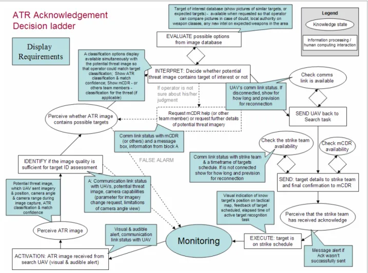
Three main decisions (D2, D3, and D4) from the event flow diagram were determined to be sufficiently complex to warrant the construction of detailed decision ladders, and ultimately the identification of display requirements for these complex decisions (Figures 2 and 3). The left-side of each decision ladder represents the information gathering and analysis aspects of the decision-making process, while the right-hand side shows the actions necessary to execute a decision. Each decision ladder depicts the states of knowledge in ovals and information-processing and human-computer (or human-human) interaction activities in rectangles. Each ladder begins with an activation event. The corresponding display requirements for relevant states in a decision-ladder are modeled in blue callout figures besides the corresponding states and activities.
For example, Figure 2 depicts the decision ladder with corresponding display requirements for detecting whether a UAV has found a target. If the operator notices that the imagery sent by the UAV’s onboard automatic target recognition (ATR) system does not contain an actual target, he could decide to release the UAV from its current loiter position over the target area so that it can return to its surveillance task. If the imagery contains a target, he will need to classify this target in order to submit the target details to the strike team and to the mission commander. Typically, before he can reach a decision, the operator must first obtain more information to be certain that the contents of the received imagery are sufficient for starting the target classification process. Once the image quality is deemed satisfactory, the operator can determine whether the imagery contains a target and, if appropriate, begin to classify the threat. To evaluate his decision, the operator can access a database or ask for other team members’ assistance. To conclude this activity, the operator must release the UAV from its current loiter tasking, and inform the strike team and mission commander of the target details. Figure 3 depicts the same decision ladder, augmented with corresponding collaborative awareness requirements that were identified as important for supporting the collaborative aspects of this particular UAV operator decision.
12
Figure 2. Decision ladder (augmented by display requirements) leading to the Automatic Target Recognition (ATR) acknowledgement.
Figure 3. Decision ladder (augmented by collaboration awareness) leading to the Automatic Target Recognition (ATR) acknowledgement.
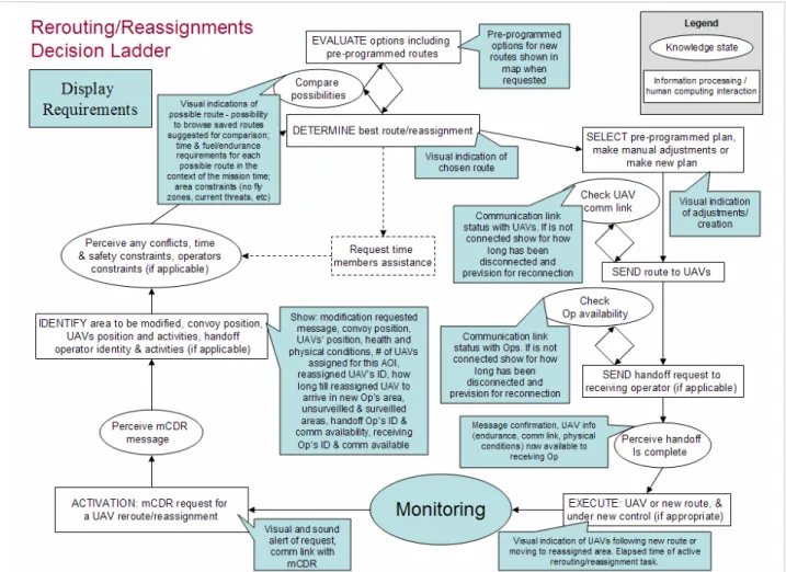
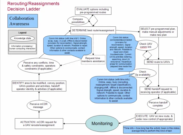
Figure 4 depicts the decision-making process for determining an appropriate UAV route modification, augmented with corresponding display requirements that were identified as critical to support this decision process. This decision to reroute or reassign a UAV in the AOI would be made when the UAV operator received an order from the mission commander, likely in response to a critical event that is affecting the team’s surveillance performance (e.g., a downed UAV). The operator needs to perceive the request and determine which UAV(s) are involved, the current areas constraints, and if appropriate, the receiving operators’ availability (in the case of a reassignment), and any related temporal conflicts and/or UAV limitations. In order to select an appropriate route for the UAV re-tasking, the operator can access a route database, make manual adjustments in pre-programmed paths or create his own route. The ability to compare various route requirements, such as time, fuel and endurance, would facilitate this process. Once an appropriate route is chosen, the UAV operator must send the plan modifications to the appropriate UAV(s) and to the appropriate operator (if applicable). The additional information required to analyze and implement this decision effectively is detailed in the display requirements shown in Figure 4. Figure 5 depicts the Rerouting/Reassignments decision ladder, augmented with corresponding collaborative awareness requirements.
14
Figure 5. Decision ladder (augmented by collaboration awareness requirements) leading to rerouting/ reassignments.
3.5 Summary of Requirements Generated from the CTA
The CTA produced significant information requirements for supporting the multi-UAV operators during the UAV ground force protection task. These requirements can be broadly categorized as requirements for providing geospatial information, alerts and feedback information, communication and availability, team information, vehicle related requirements, temporal information, target ID task requirements, and reassignment/ rerouting task requirements. These requirements are summarized in Table 3, grouped by these broad categories. For each requirement, Table 3 also indicates whether it originated from the analysis of the situation awareness requirements (SA), from the display requirements detailed in the decision ladders (Display) and/or from the collaboration awareness requirements detailed in the decision ladders (CA).
16
Table 3. Summary of requirements generated by the CTA
Type Requirement description Source
Tactical map SA
Visual indication of operator's AOI SA Number of UAVs assigned each this AOI Display Visual indication of geo-spatial boundaries SA
Visual indication of convoy's current position & planned route SA & Display Visual indication of UAVs path in geo-spatial context SA
Display UAVs' current & future positions and path SA & Display Visual indication of surveilled & unsurveilled area SA & Display Area constraints (no fly zones, current threats, etc) Display Indicate if there's a region in the AOI where communication is difficult to connect SA
Indicate potential/known threat position SA & Display Estimated distance range of target to convoy SA
Visual indication of UAV route modification SA
Geospati
a
l Info
Visual indication of UAV’s reassignment to a new area/operator Display Error message/alert clarification SA
Alert (visual & audible) of potential threat detection from UAV SA & Display Alert when mCDR requests a UAV reroute/reassignment SA
Alert of unsuccessful data or communication exchange Display Alert if pressure is too high SA Alert if UAV experiences a major system manfunction SA Alert if camera is malfunctioning SA Alert if UAV has been attacked / destroyed SA Alert if the operator is taking too long to start potential threat recognition SA Alert when some comm link is lost or regained for all contacts SA
Feedback of scheduled target strikes SA & Display Handoff message confirmation Display
Alerts & F
eedb
ack Info
Indicate if UAV has been destroyed, reassigned or JSTARS was requested SA
Strike team comm link status (with time info): Online, busy, offline or disconnected. SA, Display & CA Communication link status with the UAVs (connected/disconnected) SA, Display & CA mCDR's comm link status (with time info): Online, away, busy, in a call, offline &
disconnected. SA, Display & CA Op's comm link status (with time info): Online, away, busy (rerouting, reassignment,
target classification), changing shift, offline & disconnected. SA, Display & CA Communication link status with injured UAV (connected/disconnected) SA & CA
Operator constraints Display
Handoff/ Receiving Op’s communications availability SA & Display Current communication connections among stakeholders SA
Predicted communication connections among stakeholders SA
Expected availability of strike team in the context of the mission activities SA, Display & CA Strike Team weapons capability & availability SA
Connection's signal strength, speed, duration & network (Possible to repair) CA Show other options to communicate with relevant team member CA
Commun icati o n & avail abi lity
Show whether other contact is available to assist Op CA Whether other UAVs are available for reassignment if UAV is attacked or malfunctions SA
Handoff/receiving operator identity & activities SA & Display
T
eam
Table 3. Summary of requirements generated by the CTA (cont’d)
Type Requirement description Source
Op's UAV's system & health status (fuel/ oil temperature/ destroyed) SA & Display
Safety route SA
Predictions of health & status for each Op's UAVs SA Indicate current UAVs' location & activities and planned UAVs' location & activities SA Indication of endurance of Op's UAV under the current conditions (technical details of system
failures) SA Vehic le Re late d Req u irem ents UAV limitations SA Mission Time SA
Time that the potential threat was discovered SA Elapsed time since the potential target was found SA Time that the UAV has been attacked/destroyed SA Expected time to surveil critical area SA UAV potential endurance without repair after a malfunction SA Estimated time for UAV to return to base, get repaired, & go back to the surveillance task upon
UAV malfunction SA
Indicate how long the communication link has been disconnected SA & Display Estimated time for UAV to start safety route in case of lost communication with operators SA
Elapsed time of active operator task Display Estimated time for reassigned UAV to arrive in new area SA & Display Estimated time for a relevant team member to perform a task CA
Average time that a team member performs a particular task CA Predicted time UAV is going to be inside an difficult communication connection region CA Elapsed time UAV remained in difficult communication connection region CA
Temporal Info
Expected mission time for each UAV SA
Indicate which UAV is detecting a potential threat SA & Display Indicate camera angle and range during image capture SA & Display Camera capabilities (Parameter for imagery change request, Limitations of camera angle view) SA & Display Show image of potential threat SA & Display Ability to request a new image SA
ATR classification & match confidence SA & Display Show options for potential threat classification (e.g.: Not a target, Vehicles, Comms Equipment) SA
Ability to compare ATR image received with other images from a database SA Target of interest database (show pictures of similar targets, or expected targets) Display Ability to request help from mCDR (or other Ops or any other local authority) with threat
classification task SA & Display Ability to share threat classification info with mCDR (and others) SA
Indicate whether a local weapons authority is available or if there is any new intel on weapons
in the area Display
Show mCDR (or other Ops or any other local authority) classification for the threat SA & Display Estimate importance of the target to the mission goal SA
Show operator classification for the threat SA Further intelligence about the target that attacked/destroyed the UAV SA
T a rget ID T a sk Requ ireme n ts
18
Table 3. Summary of requirements generated by the CTA (cont’d)
Type Requirement description Source
Indicate route modification request Display Indicate which UAV is going to be reassigned & its position SA Indicate current route for relevant UAVs SA
Visual indications of possible pre-planned route (for rerouting task) SA & Display Ability to make a manual route adjustment on the pre-programmed UAV routes and save
solution SA
Ability to browse saved UAV routes suggested for comparison Display Ability to compare possible routes options ("what if") SA Show fuel/endurance requirements for each possible route in the context of mission time
requirements Display
Time requirements for each UAVs' possible new routes (in relate to the mission time &/or
convoy route) SA & Display
Reassi gnm ent/ Rerouti ng T a s k Req u irem ents
3.6 UAV Operator Display Designs
Based on the requirements listed in Table 3, a three-screen UAV operator display was developed. As shown in Figure 6, these three screens consist of a Map Display (Figure 6a), a Communications Display (Figure 6b), and a Tasking Display (Figure 6c). This section summarizes the design of these displays. Further details of how these display designs satisfy the requirements listed in Table 3 are provided in Appendix A.
Figure 6. UAV Operator Display Designs: (a) Map Display, (b) Communications Display, and (c) Tasking Display.
(a) (b)
20
3.6.1 Map Display
The main purpose of the Map Display, shown in Figure 7, is to provide the UAV operator an up-to-date view of the main mission assets (e.g., convoy, UAVs, targets) in the context of their assigned area of interest (AOI), satisfying the geospatial information requirements generated by the CTA. The symbology used on this display is primarily based on standard military display symbology from MIL-STD-2525B (DOD, 1999), modified to satisfy the information requirements generated by the CTA for our futuristic task environment.
In particular, the map symbology is designed to dynamically change through the mission to enhance the UAV operator’s awareness of possible threat and UAV tasking issues. For example, areas of the map which have not yet been surveilled are indicated by a semi-transparent black overlay. When a UAV surveils an area, that area of the map is cleared. Thus, this operator’s current surveillance progress is indicated by the relative amount of clear and black areas show in the operator’s AOI. Ideally, these areas would fade back to black as time passes and the surveillance data ages (Bisantz et al., 2006).
Team AOI map Mission time View filters UAV reroute/ reassignment time Operator AOI map Convoy threat summary & strike schedule
Figure 7. Map Display.
When one of the UAV’s being controlled by the operator detects a possible target through its onboard automatic target recognition (ATR) system, an orange target symbol is displayed on the map in the location of the detected target and the symbol of the UAV that detected the target is displayed as orange. Once the operator has finished confirming the target (see Section 3.6.3), the
UAV symbol returns to its nominal blue color and the target is displayed as red, indicating a known threat.
The Map Display also provides various view filters to enable the operator to show or hide extra display information, as needed during the mission. For example, weapons range rings can be shown around identified targets. These rings indicate the UAV’s and the convoy’s relative distance to threats in the operator’s AOI.
Though the main functionality for UAV replanning activities is provided by the Tasking Display (see Section 3.6.3), the Map Display provides some temporal awareness support for these tasking activities by displaying the elapsed time of an active rerouting or reassigning task, and the remaining time until a reassigned UAV arrives at its new AOI.
To assist the UAV operators in communicating and coordinating with their UAV team members, and to help them understand how their task activities and performance relate to the team’s progress towards their overall mission objectives, a scaled view of the Team AOI map is provided at the top of the Map Display. This map provides an up-to-date view of the main mission assets (e.g., convoy, UAVs, targets) in the context of the team’s AOI. Each of the UAV operator’s AOI are indicated with a dashed outline, with the current operator’s AOI highlighted with a blue outline.
Finally, the bottom of the Map Display contains an up-to-date Threat Summary timeline that indicates the current and expected safety level of the convoy within the operator’s AOI. This timeline indicates when the convoy is or is expected to be in range of any unsurveilled areas (i.e., a potential threat, shown as a yellow time window) or in range of a known threat (shown as a red time window). This timeline also shows the up-to-date target strike schedule. Identified targets that are scheduled to be destroyed are shown as red diamonds in the last row of the timeline. The position of a target on the timeline indicates the time it is expected to be destroyed by the external strike team. If the convoy’s planned route is expected to pass within weapons range of a scheduled target, a black line is displayed between the target’s symbol on the strike schedule and the beginning of its corresponding time window in the row above.
3.6.2 Communications Display
The main purpose of the Communications Display, shown in Figure 8, is to assist the human-human and human-human-machine communication and coordination within the overall UAV system. This display provides an up-to-date view of the current activities and communications availability of all UAV team members and UAV mission stakeholders. It also displays the health, system and communication status of all UAVs under the operator’s control, and various communication windows to facilitate receiving and sending of communications and system messages.
In particular, the Communications Display provides a persistent team communications window that serves as a team chat room that enables all UAV team members to communicate as a group. That is, all messages sent to this window will be received and archived by all UAV team members. To facilitate more one-on-one communications, the Communications Display also enables the operator to open a private chat window below the team chat by selecting a team
22
requests a private chat with this operator, the ‘Comm’ button contained in the personnel list item representing that person will be highlighted with light orange (see Figure 8), and a new communications tab will appear in the private chat panel. The operator can open the private chat by either selecting the ‘Comm’ button or selecting the private chat tab.
Team communications (chat room) Connectivity, availability & activity of team members & other
stakeholders
Individual communications
(private chat) UAV Alerts &
status messages
Connectivity, activity, & health & status of UAVs
Figure 8. Communications Display.
Finally, this display provides a separate window containing messages and alerts received from the UAVs under the operator’s control or from the computer system. Normal messages are displayed in plain black text, urgent messages indicating off-nominal UAV or system conditions are highlighted in yellow, and emergent messages indicating off-nominal or emergency UAV or system conditions are highlighted in red.
3.6.3 Tasking Display
The Tasking Display, shown in Figure 9, comprises a set of tabbed panels that provides the necessary task functionality related to specific UAV operator task activities, including Target Identification and UAV Replanning (i.e., rerouting, reassignment, and return to base). The Target identification / classification panel enables the UAV operator to classify potential threats detected by the UAVs’ onboard automatic target recognition (ATR) systems. The UAV replanning panel enables the UAV operator to reroute a UAV, to reassign a UAV to a different UAV operator (an operation that requires a transfer of UAV control from one operator to another), and to command the UAV to return to base.
The design of the Target identification / classification panel is shown in Figure 9a. This panel indicates which UAV detected the possible threat and the associated details, including the imagery captured by the UAV, the ATR system’s threat classification, and elapsed time of threat detection. In the target classification window, the UAV operator can agree with the ATR classification, change the target classification, or veto the classification to indicate the image
does not contain a known threat. To facilitate the target classification activity, the bottom portion of this panel enables the UAV operator to browse through different classification options from a target database (bottom left) or to request classification assistance from other members of the UAV team (bottom right). Finally, to facilitate the operator’s ongoing monitoring responsibilities, the top of this panel provides the current health and status of the operator’s UAVs. UAV health & status Automatic target recognition details Target classification Possible target data panel Request assistance panel (a) UAV replanning options (Reroute, Reassign, Send to Base) Expected UAV health & status
per planned route
Operator status
Team AOI with current operator AOI highlighted Replanning task functions panel Replanning task list (b)
24
The design of the UAV replanning panel is shown in Figure 9b. This panel provides an up-to-date view of the Team’s AOI, with the current operator’s AOI highlighted. This panel enables the operator to modify the planned route for one or more of their UAVs within their AOI or across the Team’s AOI (or beyond if necessary). Route replanning activities are performed in response to a request from other UAV team members or mission stakeholders, typically the mission commander. Replanning requests are displayed in a list in the upper left corner of the UAV replanning panel. Route modifications are performed by creating, adjusting, or deleting route waypoints in the Team AOI window. The lower right panel provides the operation the specific functionality associated with the current replanning activity, such as functionality for creating, viewing, saving, deleting various route options during the UAV rerouting task. Finally, the lower left window in the UAV replanning panel displays the expected UAV health and status for each displayed route option to enable the comparison of potential UAV route plans.
4 Conclusion and Future Work
This report proposes a set of displays designs to assist operators controlling multiple, semi-autonomous unmanned aerial vehicles (UAVs) engaged in collaborative, time-critical command and control operations. These displays incorporate a number of design concepts aimed at satisfying design requirements generated from a cognitive task analysis of a UAV operator’s role in a representative time-critical ISR operation involving a team of multi-UAV operators. These design concepts include various mechanisms for providing ongoing and expected status of operator tasking activity in relation to the overall mission goals, ongoing status of other team members and UAV activities, communications availability, alerting mechanisms related to health and status, and support for general team communication and coordination as well as for specific communications in relation to specific task activities (e.g., receiving assistance with a target classification activity).
To understand the effectiveness of these proposed displays, implementation and laboratory user testing of these displays within an existing synthetic task environment (Scott et al., 2007) are planned as follow-on to this work.
5 References
Bisantz, A.M., Pfautz, J., Stone, R., Roth, E.M., Thomas-Meyers, G. & Fouse, A. (2006). Assessment of Display Attributes for Displaying Meta-information on Maps. In Proceedings of HFES 2006: Human Factors and Ergonomics Society 50th Annual Meeting, October 16-20, 2006, San Francisco, CA, USA, HFES, pp. 289-293. Carroll, J.M., Neale, D.C., Isenhour, P.L., Rosson, M.B. & McCrickard, D.S. (2003).
Notification and Awareness: Synchronizing Task-Oriented Collaborative Activity. International Journal of Human-Computer Studies. 58, pp. 605-632.
Carroll, J.M., Rosson, M.B., Convertino, G. & Ganoe, C.H. (2006). Awareness and Teamwork in Computer-Supported Collaborations. Interacting with Computers. 18(1), pp. 21-46.
Nehme, C.E., Scott, S.D., Cummings, M.L. & Furusho, C.Y. (2006). Generating Requirements for Futuristic Heterogeneous Unmanned Systems. In 50th Annual Meeting of the Human Factors and Ergonomic Society, October 16-20, San Francisco, CA.
Rasmussen, J. (1983). Skills, Rules, and Knowledge; Signals, Signs, and Symbols, and Other Distractions in Human Performance Models. IEEE Transactions on Systems, Man, and Cybernetics. SMC-13(3), 257-266.
Scott, S.D., Rico, A.E., Furusho, C.Y. & Cummings, M.L. (2006). Designing Decision and Collaboration Support Technology for Team Supervision in Multi-UAV, Time-Sensitive Targeting Operations, Technical Report HAL2006-04, Cambridge, MA, USA, MIT Humans & Automation Lab.
Scott, S.D., Wan, J., Rico, A.E., Furusho, C.Y. & Cummings, M.L. (2007). Aiding Team Supervision in Command and Control Operations with Large-Screen Displays. In
Proceedings of HSIS 2007: ASNE Human Systems Integration Symposium, March 19-21, 2007, Annapolis, MD, USA.
26
Appendix A
Requirements Mapping for UAV Operator Displays
This appendix provides details of how the proposed UAV operator displays presented in Section 3.6 satisfy the information and functional requirements generated by the cognitive task analysis. As summarized in Table 3, requirements generally fell into eight different categories: geospatial information, alerts and feedback information, communication and availability, team information, vehicle related requirements, temporal information, target ID task requirements, and reassignment/rerouting task requirements. The following subsections detail how the proposed UAV operator displays satisfy the requirements falling under each of these requirements categories.
A.1 Geospatial Information Requirements Requirements:
- Tactical map
- Visual indication of convoy's current position & planned route - Visual indication of geo-spatial boundaries
- # of UAVs assigned for this AOI
As shown in Figure 10, The Map Displays provides the operator an updated view of the Team’s area of interest (i.e., the mission map), which shows the convoy’s current position (blue rectangular icon with interior crossed lines), the planned convoy route (thick back line), and the geospatial boundaries for each UAV operator’s AOI (dashed outlines), and for the mission as a whole (entire map). The current operator’s AOI is highlighted in blue outline. It also provides visual information about the number of UAVs assigned for each region of the mission area (semi-elliptical icons).
Figure 10. General geospatial information on the Map Display. Requirements:
- Visual indication of operator's AOI
- # of UAVs assigned for this AOI
As shown in Figure 11, the Map Display provides the operator an updated view of their own AOI. Additionally, using a semi-transparent overlay, the AOI shows which area have been surveilled (clear) and which have yet to be surveilled (dark gray). The AOI also shows the current position and tasking of each of the UAVs under the operator’s control in the AOI.
Figure 11. Map of the operator’s area of interest (AOI) on the Map Display. Requirements:
- Visual indication of UAVs path in geospatial context
- Display UAVs' current & future positions and path
The Map Display also allows operators to display the planned routes of each of the UAVs under their control by toggling on the appropriate view filter located in the View Filters panel (Figure 12). The UAV route filter enables the operator to view the route of one, two, or three (all) of their UAVs. The ability to show or hide this view was provided to minimize operator distraction and visual clutter in the AOI map.
28
Requirement:
- Area constraints (hazards, no fly zones, current threats, etc.)
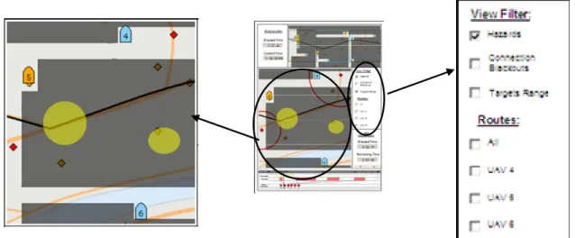
Another view that can be enabled through the View Filters on the Map Display is a visual indication of the geospatial constraints in the operator’s AOI (e.g., known threats, no fly zones, etc.). Selecting the “Hazards” filter displays the local constraints as yellow, partially transparent polygons corresponding to the geospatial boundaries of areas of which the UAV routes should avoid (Figure 13).
Figure 13. Hazard areas in the operator’s AOI on the Map Display. Requirement:
- Indicate if there is a region in the AOI where communication
connections may be difficult
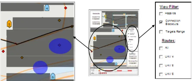
Similar to the visualization of the local area Hazards, the operator can display areas known to cause communication difficulties on the Map Display. Selecting the “Connection Blackouts” filter on the View Filters panel graphically represents such areas in the operator’s AOI as blue, partially transparent polygons, corresponding to the geospatial boundaries of these known areas (Figure 14).
Figure 14. Connection Blackout areas in the operator’s AOI on the Map Display. Requirements:
- Indicate potential/known threat position - Estimated distance range of target to convoy
Given the importance of this information, it is displayed in number different ways. As shown in Figure 15 and described in Section 3.6.1, the bottom of the Map Display provides a timeline that summarizes the current and expected threat level of the convoy relative to potential threats (i.e. unsurveilled areas) and to known threats (i.e. identified targets). This timeline also shows the target strike schedule (i.e., the expected time the strike team will destroy the identified targets).
Figure 15. Convoy threat summary and strike schedule on the Map Display.
The Map Display also provides this information (qualitatively) through the target range filter (Figure 16). Displaying the ranges to the target enables the operator to visually estimate the convoy’s distance in relation to an identified target area. The persistent dark gray semi-transparent overlay indicating unsurveilled areas enables the operator to visually estimate the convoy’s distance to any potential threats in their AOI.
30
Figure 16. Target range rings on the Map Display.
Precise information related to the convoy’s distance from a known threat is also provided during the target classification task on the Target identification panel on the Tasking Display (Figure 17).
Figure 17. Estimated distance of detected threat from convoy on Target identification/classification panel on the Tasking Display.
Requirement:
- Visual indication of UAV route modification
The UAV replanning panel in the Tasking Display provides a visual display of the route modification when the operator chooses to reroute a UAV. As shown in Figure 18, the current UAV route is presented as a green line, while the potential route modification is presented as a blue line.
Figure 18. UAV Route modification on the UAV replanning panel in the Tasking Display.
Requirement:
- Visual indication of UAVs reassigned to a new area/operator
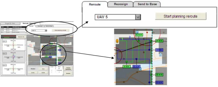
The UAV replanning panel in the Tasking Display enables a reassignment route to be visualized as it is planned (Figure 19). The operator must select one of their current UAVs to be reassigned (left drop down box in the Reassign tasking panel, upper right Figure 19) and a destroyed UAV whose route the reassigned UAV should take over (right drop down box in the Reassign tasking panel, upper right Figure 19). However, the second UAV may be in another operator’s AOI, thus requiring a UAV handoff or transfer of control. As shown in Figure 19, a possible route for reassignment can be created. The black dots indicate possible route waypoints that can be selected by the operator during the reassignment route creation.
32
A.2 Alerts and Feedback Information Requirements Requirements:
- Error message/alert clarification
- Message alert of unsuccessful data or communication exchange - Visual & sound alert if pressure is overload
- Visual & sound alert if UAV experience a major system malfunction - Visual & sound alert if camera is broken
- Alert when some link is lost or regained to all the contacts
- Alert if the operator is taking too long to start the potential threat recognition
The Alerts & Clarification window on the Communications Display provides this information to the operator (Figure 20). As discussed in Section 3.6.2, this window provides the operator any UAV or system related messages. Normal messages are displayed in plain black text, warning messages indicating expected off-nominal UAV or system conditions are highlighted in yellow, and alert messages indicating off-nominal or emergency UAV or system conditions are highlighted in red.
Figure 20. Alerts and Clarification Window on the Communications Display. Requirement:
- Feedback of scheduled target strikes
As discussed above, the Map Display provides a visual timeline of the current target strike schedule. Additionally, the Communications Display provides private chat facilities to assist operator communications with representatives on the strike team (Figure 21).
Figure 21. Private chat facilities for communicating with the strike team, on the Communications Display. Requirements:
- Alert (visual & audible) of potential threat detection from UAV
- Visual alert warning if UAV destroyed by an unknown or known target - Indicate if UAV (under the team members' control) have been destroyed,
reassigned or JSTARS was requested
This information is provided by the Alerts & Clarification window (Figure 20). Some requirements are provided in multiple, redundant ways, given their importance. For example, when a UAV detects a potential threat, an alert message is provided in the Alerts & Clarification window, and the UAV icons changes to orange (regular surveillance color is blue). Similarly, when a UAV is destroyed, its corresponding icon turns gray in the Map Display (Figure 22).
Potential target detected
Shot down UAV
Surveillance
34
Requirements:
- Alert when mCDR requests a UAV reroute/reassignment - Handoff message confirmation
When the mission commander requests a UAV route plan modification or an alert is received related to a completed UAV handoff, a message is shown at the top of the UAV Replanning panel of the Tasking Display and the corresponding tab turns orange (Figure 23).
Figure 23. UAV replanning requests in the UAV Replanning panel of the Tasking Display. Requirements:
- Visual & sound alert if UAV has been attacked
When a UAV is attacked, a message is sent to the Alert & Clarification window (Figure 20). Also, it is always possible for the operator to know the health and status of his UAVs by looking at either the Communications Display or the Target Identification panel of the Tasking Display (Figure 24). The current health is indicated by a green status bar.
Figure 24. UAVs’ health status information on the Communications Display (top) and the Target Identification panel on the Tasking Display (bottom).
A.3 Communication and availability Requirements:
- Strike team comm link status (with time info): online, busy, offline or disconnected. - Communication link status with the UAVs (connected/disconnected) mCDR's comm
link status (with time info): Online, away, busy, in a call, offline & disconnected.
- Op's comm link status (with time info): Online, away, busy (rerouting,
reassignment, target classification), changing shift, offline & disconnected.
- Communication link status with injured UAV (connected/disconnected) - Connection's signal strength, speed, duration & network (Possible to repair) - Show whether other contact is available to assist Op
- Operator constraints
- Handoff/ Receiving Op’s comm availability
- Current communication connections among stakeholders - Predicted communication connections among stakeholders
- Availability of strike team to schedule target strike in the context of the mission
activities
36
These requirements are satisfied by the Comm Status bar of the Communications Display (Figure 25).
Figure 25. Communications link & status information for each operator and UAV on the Communications Display.
Operator status information is also provided on Tasking Display, on both the Target Identification and UAV Replanning panels (Figure 26).
Figure 26. Operators’ status information on both panels of the Tasking Display: on the Target Identification panel (top) and on the UAV Replanning panel (bottom).
Requirement:
- Show other options to communicate with a relevant team member
The Communications Display offers two different instant messaging options. The first one is a general chat “room” where conversations can be seen by every user (unless the private option is chosen) (Figure 27). In this chat, the operator can select to whom he would like to direct the message, though all messages are visible to the entire team. It is also possible to call a selected team member and also start an audio conference call with multiple parties.
Figure 27. Team chat tool on the Communications Display.
The second chat tool is activated when the operator clicks the “Comm” button in the selected group member Comm Status bar. This tool enables the operator to initiate a private chat with the chosen user (Figure 28). This tool also enables the user to initiate or accept a requested audio or video chat, and share files with the selected user.
38
A.4 Team Info Requirement:
- Whether another UAV will possibly be reassigned
This information is also provided in the alerts & clarification window on the Communications Display (Figure 20).
Requirement:
- Handoff/receiving operator identity & activities
This information can be obtained in the Comm Status bar on the Communications Display (Figure 25).
Requirement:
- ID/Position in the context of the mission activities of UAV attacked/destroyed
This information is provided on all three displays when the associated UAV icon changes color to gray.
A.5 Vehicle Related Requirements Requirements:
- Op's UAV's system & health status (fuel/ oil temperature/ destroyed) - Safety route
- Predictions of health & status of each Op's UAVs
- Indicate current UAVs' locations & activities and planned UAVs' locations &
activities
- Indication of endurance of Op's UAV under the current conditions (technical details
of system failures)
- UAV limitations
This information is provided in the Comm status bar on the Communications Display, and is also provided on the Target Identification panel on the Tasking Display (Figure 24). Given the importance of UAV status information, it the Alert & Clarification window in the Communications Display will also provide health and status information whenever critical state changes or emergencies occur (Figure 20). Finally, the UAVs’ locations can always be seen in the Map Display.
A.6 Temporal Info Requirements:
- Mission Time
The updated mission time is provided on the Map Display.
Figure 29. Mission clock on the Maps Display. Requirements:
- Time that the potential threat was discovered - Elapsed time since the potential target was found
Temporal information related to detected potential targets is provided in the Target Identification panel of the Tasking Display (Figure 30).
Figure 30. Potential target detection time on the Target Identification panel of the Tasking Display. Requirements:
- Time that the UAV has been attacked/destroyed
40
Requirements:
- Elapsed time of active rerouting/reassignment task. - How long until reassigned UAV arrives in new area?
Temporal information related to UAV replanning is provided in the Map Display (Figure 31).
Figure 31. UAV Reroute/Reassignment elapsed/remaining time on the Map Display. Requirements:
- How long a relevant team member is performing a task? - Average time that a team member perform some kind of task
- Predicted time UAV is going to be inside a difficult communication connection
region
- Elapsed time UAV remained in difficult communication connection region - Expected mission time for each UAV
- How long should it take to the UAV start the safety route in case of lost
communication with operators?
- How long would UAV take to return to base & subsequently resume the surveillance
task? (UAV malfunction)
- Expected time to surveil critical area
- How long can UAV survive without doing anything about malfunction? - Indicate how long the communication link has been disconnected
Temporal information related to team member and UAV activities is provided in the Comm status bar on the Communications Display (Figure 25).
A.7 Target ID Task Requirements Requirement:
- Indicate which UAV is detecting a potential threat
The first indication that a UAV has detected a potential threat is that the associated UAV icon changes to orange in the map and status areas of the three displays. Next, new information is populated by the system into the Target Identification panel of the Tasking Display. The Target Identification panel tab displays an orange camera icon (indicating that a target has been detected). Also, once the panel is opened, an orange camera icon is also displayed on the UAV health and status bar beside the associated UAV (Figure 32). This information is also provided on the UAV health and status area of the Comm status bar in the Communications Display (Figure 25).
Figure 32. Indication of which UAV has detected a potential target on the Target Identification panel of the Tasking Display.
Requirements:
- Indicate camera angle and range during image capture
- Camera capabilities (Parameter for imagery change request, limitations of camera
angle view)
Camera information is displayed as pop-up information once the operator moves the mouse over the picture taken by the UAV in the Target Identification panel of the Tasking Display.
Requirements:
- Show image of potential threat - Allow requests for a new image
- ATR classification & match confidence
The UAV potential threat imagery and the potential target classification of the detected target are displayed in the Target Identification panel of the Tasking Display (Figure 33). This display also enables the operator to request a new image of the potential target.
42
Figure 33. Potential target imagery, imagery information, and possible target classification information on the Target Identification panel of the Tasking Display.
Requirements:
- Show options for potential threat classification (e.g.: Not a target, Vehicles, Comm
Equipments)
The options for target classification are presented in the Target Identification panel of the Tasking Display (Figure 34).
Figure 34. Target classification options on the Target Identification panel of the Tasking Display. Requirements:
- Ability to compare ATR image received with others images (database)
- Target of interest database (show pictures of similar targets, or expected targets) The Target Identification panel of the Tasking Display enabled the operator to compare the potential target picture with pictures from a general or a specific database (Figure 35).