HAL Id: inria-00350653
https://hal.inria.fr/inria-00350653
Submitted on 7 Jan 2009
HAL is a multi-disciplinary open access
archive for the deposit and dissemination of
sci-entific research documents, whether they are
pub-lished or not. The documents may come from
teaching and research institutions in France or
abroad, or from public or private research centers.
L’archive ouverte pluridisciplinaire HAL, est
destinée au dépôt et à la diffusion de documents
scientifiques de niveau recherche, publiés ou non,
émanant des établissements d’enseignement et de
recherche français ou étrangers, des laboratoires
publics ou privés.
Real-time tissue tracking with B-mode ultrasound using
speckle and visual servoing
A. Krupa, G. Fichtinger, G.D. Hager
To cite this version:
A. Krupa, G. Fichtinger, G.D. Hager. Real-time tissue tracking with B-mode ultrasound using speckle
and visual servoing. Int. Conf. on Medical Image Computing and Computer-Assisted Intervention,
MICCAI’07, 2007, Brisbane, Australia. pp.1-8. �inria-00350653�
Real-time Tissue Tracking with B-Mode
Ultrasound Using Speckle and Visual Servoing
Alexandre Krupa1
, Gabor Fichtinger2
, and Gregory D. Hager2
1 IRISA - INRIA Rennes, France, [email protected] 2 Engineering Research Center, Johns Hopkins University, USA,
{gabor,hager}@cs.jhu.edu?
Abstract. We present a method for real-time tracking of moving soft tissue with B-mode ultrasound (US). The method makes use of the speckle information contained in the US images to estimate the in-plane and out-of-plane motion of a fixed target relative to the ultrasound scan plane. The motion information is then used as closed-loop feedback to a robot which corrects for the target motion. The concept is demonstrated for translation motions in an experimental setup consisting of an ultra-sound speckle phantom, a robot for simulating tissue motion, and a robot that performs motion stabilization from US images. This concept shows promise for US-guided procedures that require real-time motion tracking and compensation.
1
Introduction
Quantitative ultrasound guidance (US) has great potential for aiding a wide range of diagnostic and minimally invasive surgical applications. However, one of the barriers to wider application is the challenge of locating and maintaining targets of interest within the US scan-plane, particularly when the underlying tissue is in motion. This problem can be alleviated, to some degree, through the use of recently developed 3D ultrasound systems. However, a more practical solution is to create a means of stabilizing a traditional B-mode ultrasound imager relative to a target. This capability can be exploited in many applications, for example to automatically move the US probe to maintain an appropriate view of moving soft tissues during US scanning or to synchronize the insertion of a needle into a moving target during biopsy or local therapy.
In this paper, we present a system that is capable of fully automatic, real-time tracking and motion compensation of a moving soft tissue target using a sequence of B-mode ultrasound images. Contrary to prior work in this area, which has relied on segmenting structures of interest [1, 2], we make direct use of the speckle information contained in the US images. While US speckle is usually considered to be noise from an imaging point of view, it in fact results from the coherent reflection of microscopic structures contained in soft tissue. As such,
?The authors acknowledge the support of the National Science Foundation under
0 0.5 1 1.5 2 −0.2 0 0.2 0.4 0.6 0.8 1 1.2
Elevation decorrelation curves ρ(d)
elevation distance d (mm)
correlation value
Fig. 1.(left) Experimental decorrelation curves obtained by measuring the correlation value between 25 patches of B-scan I1 and their corresponding patches in B-scan I2
along the elevation distance d (right)
it is spatially coherent. Furthermore, an US beam is several mm wide. As a result, there is substantial overlap between US scan planes with small lateral displacements and, therefore, substantial correlation of the speckle information between successive images. Speckle correlation occurs for both in-plane and out-of-plane motion, thereby making it possible to track both out-of plane and in-plane motion, and raising the possibility of calculating full 6-DOF relative pose of speckle patches.
Initially, speckle information has been used to estimate multi-dimensional flow in 2D ultrasound image ([3]). Recently several authors ([4, 5]) have published speckle decorrelation techniques to allow freehand 3D US scanning without a position sensor on the US probe. Their techniques depend on experimentally calibrating speckle decorrelation curves from real soft tissues and/or speckle simulating phantoms. These curves (Fig. 1) are obtained by capturing B-mode images at known distances d along the elevation direction (i.e. orthogonal to the image plane) and measuring the normalized correlation coefficients for a finite number of rectangular patches fixed in the images. The imaging procedure then entails capturing an US stream by moving the probe in a given direction. The relative in-plane and out-of-plane position between each image is then estimated, off-line, from the estimated elevation distances from at least 3 non-collinear patches in the image plane. These distances are computed from the calibrated decorrelation curves using the measured inter-patch correlation value for each image patch.
In our experimental scenario, we also perform an offline calibration procedure to relate speckle decorrelation to elevation motion. However, we subsequently servo the US probe to track a user-selected B-scan target in a fully automatic, online manner. The 6-DOF motion of the target B-scan is extracted by an es-timation method using the speckle information and an image region tracking algorithm based on grey level intensity. A visual servoing scheme is then used
to control the probe displacement. Section 2 presents the methods used to ex-tract 6-DOF rigid motion of the target B-scan image. The visual servoing control laws are developed in section 3 and section 4 presents first results obtained from ex-vivo experiments where only translation motions are considered.
2
Motion extraction
The overall tracking problem is to minimize the relative position between the current B-scan (denoted by a Cartesian frame {c}) and a target B-scan (denoted by a Cartesian frame {i}). The full 6 DOF target plane position can be decom-posed by two successive homogeneous transformations: cH
i = cHp pHi where cH
p and pHi describing the in-plane and out-of-plane displacement of the
tar-get, respectively. Note that {p} corresponds to an intermediate “virtual” plane. The in-plane displacement corresponds to the translations x and y along the X and Y axes of the current image plane and the angular rotation γ around the Z axis (orthogonal to the image), such that:
cH p= cos(γ) − sin(γ) 0 x sin(γ) cos(γ) 0 y 0 0 1 0 0 0 0 1 (1)
We use a classical template tracking technique [6] to extract the in-plane motion parameters x, y, γ. This information is then used to relate the image coordinates of patches in the two images for the purposes of estimating out-of-plane motion using speckle decorrelation.
To extract the out-of-plane motion, we use the Gaussian model introduced in [4]. From experimental observations (Fig. 1), we found that the elevation distance between a patch in the target plane and the corresponding patch in the current image can be estimated by ˆd =p−2ˆσ2
ln(ρ), where ˆσ = 0.72 mm is the mean resolution cell width (identified from experimental decorrelation curves).
To compute the full out-of-plane motion, we compute the elevation distance of a grid of patches (25 in our current system), and fit a plane to this data. However, the Gaussian model does not detect the sign of the elevation distance for a given patch. Thus, we employ the following algorithm to estimate the out-of-plane position of the target out-of-plane with respect to the virtual out-of-plane {p}. We first set a random sign on each inter-patch distance and estimate (with a least-square algorithm) an initial position of the target plane using these signs. We then use the iterative algorithm we presented in [7] to determine the correct signed distances and the associated plane. This algorithm, which minimizes the least-square error of the estimated target plane, converges to two stable solutions that are symmetrical around plane {p}. The two solutions correspond to the positive and negative elevation distances z, respectively. Note that from one solution we can easily determine the second. By formulating the out-of-plane relative position as a combination of a translation z along the Z axis of plane {p} and
two successive rotations α, β around the Y and X axes of {p}, we obtain the following homogeneous transformation matrix for out-of-plane motion:
pH i=
cos(α) cos(α) sin(θ) sin(α) cos(θ) 0
0 cos(θ) − sin(θ) 0
− sin(α) cos(α) sin(θ) cos(α) cos(θ) z
0 0 0 1
(2)
The two symmetrical solutions for the 6 DOF motion are then given by the estimates:
cHb
i(+) = cHbp pHbi(+) and cHbi(−) = cHbp pHbi(−) (3)
where (+) indicates the solution obtained for ˆz > 0, with ˆα = atan(ˆa/ˆc), ˆ
θ = −asin(ˆb) and (-) indicates the solution corresponding to ˆz < 0 with ˆ
α = atan(−ˆa/ˆc), ˆθ = −asin(−ˆb). Here (ˆa, ˆb, ˆc) is the normal vector of the estimated target plane that is obtained for the solution ˆz > 0. The subscript ˆ denotes values provided by the template tracking and plane estimation methods. It will be purposely dropped in the next of the paper for clarity of presentation. This method works only locally about the target region due to the rapid rate of speckle decorrelation with out-of-plane motion. Therefore, in order to increase the range of convergence, we augment the basic algorithm with a FIFO buffer of intermediate planes {i} between the target {t} and current plane {c}. These planes, which are acquired online as the probe moves, are chosen to be close enough to be well “speckle correlated” and thus provide a “path” of ultrasound images that can be traced back to the target.
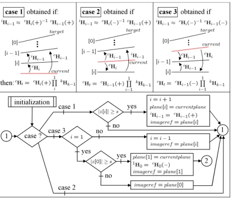
The complete algorithm summarizing our method for extracting target plane position is described in Fig. 2 (for positive elevation distances) and Fig. 3 (for negative elevation distances.) At initialization, the target plane is cap-tured in the initial B-scan image and stored in a FIFO buffer (plane) start-ing with index i = 0. The current image is also stored as the target image (imageref erence = currentplane). A small negative elevation displacement is then applied to the probe in order to obtain an initial positive elevation distance z[0] ≥ s > 0 of plane[0] with respect to the current B-scan plane. Here s is a small threshold distance fixed to guarantee speckle correlation between US images. The algorithm goes to the case of positive elevation distance. The array index is then incremented and an intermediate plane is stored (plane[i] = currentplane) with the homogeneous matrix iH
i−1 = cHi−1(+) describing the position of
plane[i − 1] with respect to plane[i] and given by (3). Each time an intermedi-ate plane is added, the target image used by the in-plane motion tracker is also updated (imageref erence = currentplane). After initialization, the configura-tion of planes corresponds to case 1 in Fig. 2, where the target plane posiconfigura-tion iscH
t= cHi(+)
Q1 i
kH
k−1. Now, we suppose that the target plane moves for
some reason. By computing (3) for cH
i and cHi−1, we can: 1) determine the
consistent pair of solutions that express the current plane relative to plane[i] and plane[i − 1], 2) determine which of cases 1, 2 or 3 is valid and 3) compute the target elevation positioncH
case 1 obtained if : case 2 obtained if case 3 obtained if th en: c as e ? initial iz ation c as e 1 c as e 3 2 c as e 2 1 y es no y es no 1 no y es
Fig. 2.(top) possible planes configurations and (bottom) process used to manage the intermediates planes when the target elevation distance is positive
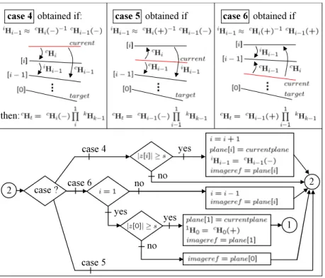
if the current plane moves a distance s beyond the top of the FIFO array, then a new intermediate plane is added or 2) if the current plane is between the top two planes of the FIFO array, then no change occurs, or 3) if the elevation distance decreases, then the last intermediate plane is removed from the FIFO array. In the latter case, a special situation arises when there are only two planes (i = 1) in the array. In this case, if the absolute value of the target elevation distance reaches the threshold s, then the algorithm switches to the second mode de-scribed in Fig. 3 which is the symmetric logic for negative elevations. For this mode, the possible configurations of planes are illustrated by cases 4 to 6 in Fig. 3. The algorithm switches back to the first mode when the target plane elevation position becomes positive again.
3
Visual servoing
Now, as the position of the B-scan target with respect to the current plane has been estimated, we move the robot (holding the probe) in order to follow the target plane. In our approach, a 3D visual servoing control scheme is used to minimize the relative position between the current and target planes. The error vector is the 6 dimensional pose vector x = (tPT
c, θu T
)T
case 4 obtained if : case 5 obtained if case 6 obtained if th en: c as e ? c as e 4 c as e 6 1 c as e 5 2 y es no y es no 2 no y es
Fig. 3.(top) possible planes configurations and (bottom) process used to manage the intermediates planes when the target elevation distance is negative
position of the current plane frame {c} with respect to the target plane frame {t}. HeretP
c is the translation vector obtained directly from the 4th column of tH
c= cH −1
t , and θu is the angle-axis representation of the rotation tRc [8].
The variation of x is related to the velocity screw v = (vx, vy, vz, ωx, ωy, ωz)T
of the ultrasound probe by ˙x = Lsv. In visual servoing, Lsis called the
interac-tion matrix and is given in this case by (cf. [9]): Ls= tR c 03 03 I3−θ 2[u]×+ (1 − sinc θ sinc2 θ 2 )[u]× ! (4) where I3 is the 3 × 3 identity matrix and [u]× is the skew matrix of the vector
preproduct linked with u. The visual servoing task (cf. [9]) can then be expressed as a regulation to zero of the pose x and is performed by applying the following control law: v = −λL−1
s x where λ is the proportional coefficient involved for a
exponential convergence.
4
Experiments and Results
We have tested the motion stabilization method on 2-DOF motions combining a translation along the image X axis (in-plane translation) and elevation Z axis
robot 1 p h a n tom U S p robe robot 2 Z X a x i s Z X X image 0 50 100 150 200 −30 −20 −10 0 10 20 30 time (s)
position of the two robots (mm)
x robot 1 z robot 1 x robot 2 z robot 2 0 50 100 150 200 −4 −3 −2 −1 0 1 2 3 4 time (s) Tracking error (mm) x (in−plane) z (out−plane)
Fig. 4. (top) experimental setup (bottomleft) evolution of the robots positions -(bottom-right) tracking error
(out-of-plane translation). The experimental, setup, shown in Fig. 4, consists of two X-Z Cartesian robots fixed and aligned on an optical table. The first robot provides a ground truth displacement for an US speckle phantom. The second robot holds a transrectal 6.5 Mhz US transducter and is controlled as described above to track a target plane. The US image is 440 × 320 pixels with resolution of 0.125 mm/pixel. A laptop computer (Pentium IV 2 Ghz) captures the US stream at 10 fps, extracts the target plane position by using a grid of 25 patches and computes the velocity control vector applied to the probe holding robot. The plots in Fig. 4 show the evolution of the robots positions and the tracking error when sinusoidal motions (magnitude of 30 mm on each axis) were applied to the phantom. The dynamic tracking error was below 3 mm for in-plane translation and 3.5 mm for the elevation translation. This error is attributed the dynamics of the target motion, time delays in the control scheme, and the dynamics of the probe holding robot. These errors could be reduced if a prediction of its variation was introduced into the control law by some method
such as Kalman filter or generalized predictive controller [10]. Adopting recent methods [11] for more accurate and efficient identification of fully developed speckle patches should also improve on tracking performance and may allow estimation of relative motion between different soft tissue elements. In order to determine the static accuracy of the tracking robotic task, we applied a set of 140 random positions to the phantom by using ramp trajectories while tracking the target plane by the robotized probe. When the probe stabilized at a position, the phantom was held motionless for 2 seconds and the locations of the two robots were recorded. We recorded a static error of 0.0219±0.05 mm (mean ± standard deviation) for the in-plane tracking and 0.0233±0.05 mm for the out-of-plane tracking, which is close to the positioning accuracy of the robots (± 0.05 mm). In conclusion, results obtained from 2-DOF in-plane and out-of-plane motions demonstrated the potential of our approach. We are presently adding rotational stages to the robots to experimentally validate full 6-DOF motion tracking and visual servoing capabilities of the current algorithm described in this paper.
References
1. P. Abolmaesumi, S. E. Salcudean, W. H. Zhu, M. Sirouspour, S. DiMaio, Image-guided control of a robot for medical ultrasound, IEEE Trans. Robotics and Automa-tion, 18:11-23, February 2002.
2. J. Hong, T. Dohi, M. Hashizume, K. Konishi, N. Hata, An ultrasound-driven needle insertion robot for percutaneous cholecystostomy, Physics in Medicine and Biology, 49(3):441-455, 2004.
3. L.N. Bohs, B.J. Geiman, M.E. Anderson, S.C. Gebhart, G.E. Trahey, Speckle track-ing for multi-dimensional flow estimation, Ultrasonics, 28(1-8):369-375, March 2000. 4. A. H. Gee, R. J. Housden, P. Hassenpflug, G. M. Treece, R. W. Prager, Sensorless freehand 3D ultrasound in real tissues: Speckle decorrelation without fully developed speckle, Medical Image Analysis, 10(2):137-149, April 2006.
5. R.-F. Chang, W.-J. Wu, D.-R. Chen, W.-M. Chen, W. Shu, J.-H. Lee, L.-B. Jeng, 3-D US frame positioning using speckle decorrelation and image registration, Ultra-sound in Med. & Bio., 29(6):801-812, 2003.
6. G. D. Hager, P. N. Belhumeur, Efficient region tracking with parametric models of geometry and illumination, IEEE Transactions on Pattern Analysis and Machine Intelligence, 20(10):1025-1039, 1998.
7. A. Krupa, G. Fichtinger, G.D. Hager, Full Motion Tracking in Ultrasound Using Image Speckle Information and Visual Servoing, in IEEE Int. Conf. on Robotics and Automation, ICRA’07, Roma, Italy, 2007.
8. J.J. Craig. Introduction to Robotics : Mechanics and Control, Addison-Wesley, sec-ond edition, 1989.
9. F. Chaumette, S. Hutchinson. Visual Servo Control, Part I: Basic Approaches. IEEE Robotics and Automation Magazine, 13(4):82-90, December 2006.
10. R. Ginhoux, J. Gangloff, M. de Mathelin, L. Soler, M.M. Arenas Sanchez, J. Marescaux, Active Filtering of Physiological Motion in Robotized Surgery Using Predictive Control, In IEEE Transactions on Robotics, 21(1):67-79, February 2005. 11. H. Rivaz, E Boctor, G. Fichtinger, Ultrasound Speckle Detection Using Low Order