INTERNATIONAL JOURNAL OF CIRCUITS, SYSTEMS AND SIGNAL PROCESSING Volume 9, 2015
Abstract— This paper presents a control strategie for a pulse with modulation (PWM) rectifier. This strategy is a voltage oriented control (VOC) which originates from field oriented control (FOC) for the induction motor, its provides a fast dynamic response since the current control loop is applied. This strategy is used to eliminate harmonic current and consequently to reduce the total harmonic distortion (THD) of the line current and improve the power factor while maintaining the DC-voltage at the required level. A classical PI controller and a FUZZY Logic Controller are used to regulate the dc bus voltage. A digital simulation in Matlab /Simulink/ SimPower System and Fuzzy logic toolbox is carried out. The steady state and dynamic result illustrating the operation and performance of the proposed control scheme are presented, consequently, it was confirmed that the novel VOC is much better than the classical one.
Keywords— Fuzzy Logic Controller, PI controller, PWM-rectifier, THD, VOC.
NOMENCLATURE ea, eb, ec: power source voltages.
uea, ueb, uec: rectifier voltages
ia, ib, ic: power source currents.
R, L, and C: line resistance, line inductance, and capacitor. S: Laplace operator.
f: frequency.
ω: frequency pulsating.
Sa, Sb, Sc: Switching state of the converter.
φ : phase voltage. is: output current.
ic: current an the end of the capacitor.
Vdc : direct voltage.
id: load current.
h: the order harmanique Rd: load resistance.
G,Ge, G∆e : gains of the Fuzzy controller. m: modulation index.
Kp, Ki : gains of the PI controller.
I. INTRODUCTION
ith the development of power electronic converter technology, all kinds of inverters based on Pulse With Modulation (PWM) have been widely used. At present, most of rectifier devices usually adopt non-controlled or semi-controlled rectification technology [1], [2], [3].
The PWM-converters ensures: - A sinusoidal current waveform; - Control the network power factor;
-The functional reversibility of the installation without resort to an auxiliary bridge in the contrary to the traditional converters[4].
Among the technical control of three-phase PWM rectifier to reduce current harmonic and improve the power factor in the power grid, there is the Voltage Orientation Control (VOC) based the voltage estimate [5].
The active power exchange must be stable by insuring a DC voltage equals to its reference so that the PWM rectifier operates with a good efficiency. This can be carried out by using a control system able to regulate the DC voltage [6].
In this paper, two techniques to control the DC-voltage are considered, the first using a PI controller and the second using a fuzzy logic controller. First, the whole system is modeled and then a simulation is undertaken under Matlab environment. The comparative study shows that the performances using the fuzzy logic controller are slightly better that those obtained using a simple PI controller. In fact, the DC voltage response shows good rejections to the disturbance of load with good dynamics. Moreover, the output voltage contains fewer harmonic reducing the THD ratio.
This work was supported in part by LATAGE research laboratory, University Mouloud Mammeri, of Tizi-Ouzou, 15000 Algeria.
Arezki Fekik is with the Electrical and Computer Engineering Department at Mouloud Mammeri University of Tizi-Ouzou, Algeria, , P.O. Box 17 , Tizi-Ouzou, Algeria, Tel:+213663118036 ; email [email protected]).
Hakim Denoun is with the Electrical and Computer Engineering Department at Mouloud Mammeri University of Tizi-Ouzou, Algeria, P.O.Box,17,Tizi-Ouzou,Algeria,Tel:+213555185198;email
Nacereddine Benamrouche is with the Electrical and Computer Engineering Department at Mouloud Mammeri University of Tizi-Ouzou, Algeria University, P.O. Box 17, Tizi-Ouzou, Algeria, ( Tel:+213772314992 ; email : [email protected]).
A Fuzzy –Logic Based Controller For Three
Phase PWM Rectifier With Voltage Oriented
Control Strategy
A
.FEKIK, H.DENOUN, N.BENAMROUCHE, N.BENYAHIA, M.ZAOUIA.
INTERNATIONAL JOURNAL OF CIRCUITS, SYSTEMS AND SIGNAL PROCESSING Volume 9, 2015
II. MODELING OF PWM RECTIFIER
The power circuit of the PWM rectifier contains a bridge of six power transistors with anti-parallel diodes, which is used to carry out the PWM generation as well as the power bidirectional conversion, the general diagram of the PWM rectifier is shown in Fig. 1. The converter is supplied by a voltage source in series with an inductance and a resistance, which model the network. Generally, the network inductance is insufficient to eliminate all the harmonics present in the current and voltage waveforms[7], [8], [9].
To attenuate the ripples due to the switching operation of the PWM rectifier, a serie filter having a more significant inductance is needed. A load and a capacitor are connected simultaneously at the output of the converter. The capacitor is used as a voltage source and allows the rectifier to also operate as an inverter [8], [9], [10].
Fig.1. General Diagram of the PWM rectifier
The logical states impose the rectifier input voltages and are given as dc c ec dc b eb dc a ea V S u V S u V S u . . .
Thus the operation principle of the rectifier is illustrated by the following matrix system:
c b a dc ec eb ea S S S V u u u 3 2 3 1 3 1 3 1 3 2 3 1 3 1 3 1 3 2
The AC side can be modeled by the following equations [13]:
dt di L Ri e u dt di L Ri e u dt di L Ri e u c c c ec b b b eb a a a ea
AC currents ia, ib and ic are generated by voltage drops at
impedances network boundaries (ea-uea), (eb-ueb) and (ec-uec),
and then these currents will be modulated through the switches to provide the D.C.current is such as [6]:
c c b b a a s S i S i S i i
The voltages vectors generated by the rectifier can be given by Table I:
S
aS
bS
cU
eaU
ebU
ecV
i0
0
0
0
0
0
V
00
0
1
3 dc V 3 dc V 3 2VdcV
50
1
0
3 dc V 3 2Vdc 3 dc V V
30
1
1
3 2Vdc 3 dc V 3 dc VV
41
0
0
3 2Vdc 3 dc V 3 dc VV
11
0
1
3 dc V 3 2Vdc 3 dc VV
61
1
0
3 dc V 3 dc V 3 2Vdc V
21
1
1
0
0
0
V
7 Table.I. Different switches configurations and thecorresponding voltage vectors (1) (2) (3) (4)
Sa Sb Sc Uea Ueb Uec ea eb ec L R ia ib ic iS id C V dc Rd icINTERNATIONAL JOURNAL OF CIRCUITS, SYSTEMS AND SIGNAL PROCESSING Volume 9, 2015 id is the current absorbed by the load, its equation depend on
the nature of this one [4] - No load :
0
d i
- For a resistive load( Rd)
d dc d R V i
- For passive inductive load
d d d dc d L i R V dt di
- For an active inductive load(Ld, Rd, E)
d d d dc d L E i R V dt di
In our study load is considered to be pureling resistance The vector representation of voltages generated by the rectifier is illustrated by Fig.2:
Fig.2. Voltage vectors generated by the rectifier III. VOC STRATEGIE
As in the Flow Oriented Control (FOC) of induction motors, the Voltage Oriented Control (VOC) and the Virtual Flow Oriented Control (V-FOC) for the grid side of the PWM rectifier is based on the transformation of the coordinates between of the fixe coordinates an (αβ) and the dq rotating coordinates, the principle of the VOC is illustrated in Fig.4 [5], [7], [10].
For the VOC active and reactive powers are controlled in an indirect way by the intermediary internal loops of the currents. The modulation block used the triangle sine control strategy (SPWM) used in [4]. This strategy is to generate PWM signals from two signals shown in Fig.3, according to the author a sinusoidal voltage control Vcontrol of a desired frequency fref is
compared with a signal form triangulaireVtrain ace greater
frequency fp [4].
When Vcontrol is greater than Vtrian the PWM output is
positive and when the Vcontrol is smaller than Vtrian the PWM
output is negative[4].
We define the modulation index m as:
ref p
f f
m
Fig.3. Description of bipolar PWM modulation
Fig.4. Basic block of the VOC scheme.
A. Study of the decouplled controller
The use of PI controllers in a three-phase reference frame presents many problems leading to static errors not compensated by the controllers. To solve this problem, the
(9) (5)
(6)
(7)
Park transformation which reference frame turns at the frequency of the he network voltage is used.
Thus the alternative variables of the currents are transformed into components of axis d and q continuous since these signals have the same frequency as the network, This requires the knowledge of the reference phase angle of the network voltage for the calculation of the transforms However, there is a coupling between the axes of the transformation of Park., therefore a variation on id causes a variation on iq [7],
[10].
The voltage equations in the revolving frame of reference (d-q) are: d q q q q q d d d d wLi v dt di L Ri e wLi v dt di L Ri e
Decoupling between the axes d and q is carried out by the variable hdandhq : dt di L Ri wLi v e h dt di L Ri wLi v e h q q d q q q d d q d d d
The system of uncoupled state is thus presented, by:
q d q d q d h h L L i i L R L R dt di dt di 1 0 0 1 0 0
It is possible to order independently the components of the current id and iq by action on hd and hq, thus, it is simple to
design the controllers. The principle of the decoupled controller is shown in Fig.5:
Fig .5. Decoupled controller
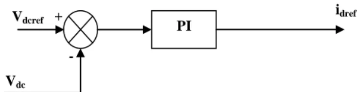
B. DC voltage regulation B.1 PI controller
The controller in the external control loop of the PWM rectifier is used to regulate the DC voltage side and to generate the magnitude of the reference line current which will be multiplied by the dc voltage to obtain the reference of the instantaneous active power to have the current reference idref
[6], [11].
To have unity power factor condition, the iqref current must
be equal to zero [8], [12]. The regulation function is ensured by a PI controller as shown in Fig .6:
Fig.6. DC voltage regulation with PI controller. The expression of the Pref active power is to be obtained by
the following expression:
dref dc
ref V i
P *
To determine the parameters of the PI controller, we make the following mathematical development.
The relationship between the power absorbed by the capacitor and the output voltage can be written as[12].:
2
* dc ref C V dt d P based on Laplace transformation, we can write
s C P U dc ref * 2 * 2
The transfer function of the PI controller can be expressed by[8]: i i p T s s s K K * 1
The transfer function of the closed loop system is given by [8]
2 0 0 0 2 2 0 2 ) 1 ( * ) ( s s s s F With : i CT 2 0 i CT 2 0 (10) (11) (12)
(13)
(14)
(15)
(16)
(17) and PI Vdcref + - idref Vdc
INTERNATIONAL JOURNAL OF CIRCUITS, SYSTEMS AND SIGNAL PROCESSING Volume 9, 2015
After calculation; we find
i p T K i i T K 1 B.2 FUZZY controller
For a good performance of the control voltage, particularly in the case of change of DC voltage reference level, the PI controller is replaced by a fuzzy controller
The new control structure of the DC voltage maintains the same model adopted when the PI controller was used. These parameters are adjusted in real time according to the disturbance [6], [8], [12], [13]:
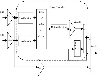
The fuzzy controller developed in this section is given by Fig .7 which the internal structure of the controller, both input values normalized using the normalization gains .
The error and varaition are difined by [6], [12], [8], [13]:
) 1 ( ) ( ) ( ) ( ) ( ) ( k k k k v k v k dcref dc
The output of the fuzzy controller is the change reference current amplitude Δidref the new amplitude adjusted at each
sampling moment is defined by: [6], [8]: ) ( ) 1 ( ) (k i k G i k
idref dref dref
Where G is the gain of the demoralization output variable The three gains are designed to act in a comprehensive manner on the control surface by enlarging or reducing the aera.
It should be noted that a proportional addition Gp is at the
exit of fuzzy controller.
The main role of this action is proportional to ensure stability in permanent regime and eliminate the static error in the steady static such that:
) ( ) ( ) 1 ( ) (k i k G i k G k
idref dref dref p
With Gp is the gain of the error
The term Gpε(k) can smooth the transition response and also
eliminate static error.
The main features of the developed controller are:
Seven fuzzy set for each input output
The function of appartenance are triangular for simplicity
Involvement uses inference Min-Max E.Mamdani
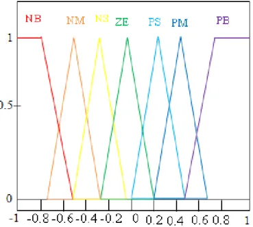
The defuzzification by center of gravityFig .7. DC voltage regulation with FUZZY controller The membership functions representing the input and the output variables are given by Fig 8, Fig.9 and Fig.10
Fig .8 Membership functions of the error
(18)
(20)
(19) and Fuzzy Controller idref(k) ε(k) ∆ε (k) Defuzzification Table of rules and inference Gε Fuzzification Fuzzification G Gp ∆idref(k) + + + + G∆ε
Fig .9 Membership functions of the variation of the error
Fig .10. Membership functions of the output
Fuzzy rules are gathered in an inference matrix shown in Table.II. NB: Negative Big; NM: Negative Medium; NS: Negative Small; ZE: Zero; PB: Positive Big; PM: Positive Medium; PS: Positive Small.
Table.II Fuzzy rules
IV. SIMULATIONANDRESULTS
To validate the effectiveness of the control strategy studied in this paper, a numerical simulation was carried out in MATLAB / Simulink environment.
The DC voltage control system is tested and the method of VOC according to a DC voltage step variation occurring at time t = 0.5 (s) from 250 (V) to 300 (V).
The efficacy of the fuzzy control DC voltage is illustrated in Figure 11. We can see that the system has become more stable we used a PI controller when the change in reference voltage continuous.
This figure exceeded completely disappears and the response time is reduced
The system parameters studied in this paper are given in Table.III.
R
0.2 Ω
L
0.016 H
C
0.0045 F
R
load100 Ω
Peak amplitude of line
voltage
120 V
Source voltage
frequency
50 Hz
DC-Voltage V
dcref250 V
Table.III. System parameters ε=Vdcref -Vdc ∆ε NB NM NS ZE PS PM PB NB NB NB NB NB NM NS ZE NM NB NB NB NM NS ZE PS NS NB NB NM NS ZE PS PM ZE NB NM NS ZE PS PM PB PS NM NS ZE PS PM PB PB PM NS ZE PS PM PB PB PB PB ZE PS PM PB PB PB PB
INTERNATIONAL JOURNAL OF CIRCUITS, SYSTEMS AND SIGNAL PROCESSING Volume 9, 2015 0 0.1 0.2 0.3 0.4 0.5 0.6 0.7 0.8 0.9 1 -50 0 50 100 150 200 250 300 350 400 Time(S) V o l t a g e ( V ) PI Controller FUZZY Controller Vdcref
Fig.11. Control system step response (Vdcref =250 to 300 V) 0 0.1 0.2 0.3 0.4 0.5 0.6 0.7 0.8 0.9 1 -0.5 0 0.5 1 1.5 2 2.5x 10 4 Time(S) P ( W ) FUZZY Controller PI Controller
Fig.12. Instantaneous active power
Fig.12 shows that when the DC voltage reaches the new reference value, the active power and consequently the line current increase and improve the power factor Fig13. For the fuzzy controller, the power increase is limited. This avoids
dangerous over currents for the system operation. To compare the PI and the fuzzy controllers the harmonic spectrums of the current are given in Fig 14 and 15. It is shown that the fuzzy controller is better than the PI controller as far as the harmonic content is concerned (THD= 2,5862 with a fuzzy controller compared to THD=3, 3006 with a PI controller).
0.6
0.65
0.7
0.75
0.8
0.85
0.9
0.95
1
-500
-400
-300
-200
-100
0
100
Time(S)
V ol t a ge & C ur r e nt ( V & A ) 0.74 0.75 0.76 0.77 0.78 0.79 0.8 -100 -50 0 50 100 Time(S) V ol t a ge & C ur r e nt ( V & A ) Va Ia PIcontroller IaFUZZYControllerFig.13. Line voltage and line current.
5 10 15 20 25 30 35 40 45 50 0 0.1 0.2 0.3 0.4 0.5 0.6 0.7 0.8 0.9 1
THD(%)= 2.5862
Fig.14. Harmonic spectrum and THD of the current with a fuzzy controller.
Rang (h)
iah
5 10 15 20 25 30 35 40 45 50 0 0.1 0.2 0.3 0.4 0.5 0.6 0.7 0.8 0.9 1
THD(%)= 3.3006
Fig.15. Harmonic spectrum and THD of the current with the PI controller.
V. CONCLUSION
In this paper, we presented a control strategy for a PWM rectifier. It concerns the use of the voltage oriented control using two types of controllers a conventional PI controller and a fuzzy controller.
Simulation results have proven excellent performance of the proposed VOC based on FUZZY controller scheme which is much better than conventional VOC based on a PI controller.
The performances are better both in transient and steady state conditions. Moreover, nearly almost sinusoidal waveforms of input currents are successfully achieved and guarantee a good regulation of the output voltage with a power factor near to unity and low THD.
REFERENCES
[1] S. Vazquez, J. A. Sanchez, J. M. Carrasco, J. I. Leon, E. Galvan, ―A model-based direct power control for three-phase power converters”,
IEEE Transactions on Industrial Electronics, 55(4),2008,
1647-165W.-K. Chen, Linear Networks and Systems (Book style). Belmont, CA: Wadsworth, 1993, pp. 123–135.
[2] C. X. Chen, Y. X. Xie, ―Direct power control of voltage source rectifier”, Proceedings of the 29th Chinese Control Conference, Beijing, 2010, 5003-5006.
[3] Liwei Zhang , Guoqiang Zheng , Jishun Li ―Direct Power Control Strategy of Three-phase PWM Rectifier”, Journal of Information &
Computational Science 10:9 (2013) 2807 2813.
[4] H. Denoun, N. Benamrouche, S. Haddad, S. Meziani and S. Ait Mamar, ―A DSP (TMS320LF2407) based implimentation of PWM for single – phase AC-DC bipolar converter with a unity power factor”, WSEAS
International Journal of Circuits, Systems and Signal Processing, Vol 5,2011, pp 354-361 ISSN-1998-4464.
[5] Graziella Giglia, Marcello Pucci, ―Comparison of Control Techniques for Three-Phase Distributed Generation Based on VOC and DPC”,
Institute on Intelligent Systems for the Automation, Palermo – Italy
I.S.S.I.A.-C.N.R .
[6] Abdelhafid SEMMAH, Ahmed MASSOUM, Habib HAMDAOUI, Patrice WIRA , “Comparative Study of PI and Fuzzy DC Voltage Control for a DPC- PWM Rectifier”, Electrical Review, ISSN 0033-2097, R. 87 NR 10/2011.
[7] Sylvain LECHAT SANJUAN, ―Voltage Oriented Control of Three‐Phase Boost PWM Converters Design, simulation and implementation of a 3‐phase boost battery Charger”, Department of Energy and Environment Division of Electric Power Engineering chalmars university of technologie Göteborg, Sweden, 2010.
[8] A Bouafia F Krim, ―A fuzzy-logic-based controller for three-phase PWM rectifier with unity power factor operation”, J.Electrical Systems 4-1 (2008): 36-50.
[9] Alberto Berzoy, Miguel Strefezza “Optimized Fuzzy Variable Structure for a Three-Phase Rectifier with power factor correction” , WSEAS TRANSACTIONS on POWER SYSTEMS Issue 8, Volume 4, August 2009 pp 275-284 ISSN: 1790-5060.
[10] Daniel Castro Carmona, Javier Fernández Mandiola, ―Design and Implementation of a Three-Phase Boost Battery Charger with PFC using Compact RIO Control System”, Department of Energy and Environment Division of Electric Power Engineering chalmars university of technologie Göteborg, Sweden, 2012.
[11] Bhanu Priya K, Dr. Rama Rao P.V.V, ―fuzzy based three phase voltage
source PWM rectifier for rapidly varying active load”, International
Journal of Advanced Research in Electrical, Electronics and Instrumentation Engineering, An ISO 3297: 2007 Certified
Organization Vol. 2, Issue 10, October 2013.
[12] J. Lamterkati1, M. Khafallah2, L. Ouboubker ,‖ Comparison of PI and Fuzzy logic DC-Link Voltage Controller for DPC PWM-Rectifier”,
International Journal of Enhanced Research in Science Technology & Engineering, ISSN: 2319-7463 Vol. 3 Issue 4, April-2014, pp:
(321-332), Impact Factor: 1.252 .
[13] Karuppanan P, Kamalakanta M , ―PI, PID and Fuzzy Logic Controlled Cascaded Voltage Source Inverter based Active Filter for Power Line Conditioners" , WSEAS TRANSACTIONS on POWER SYSTEMS Issue 4, Volume 6, October 2011 pp 100-109 ISSN: 1790-5060. Rang (h)
iah
(A)
H. Denoun was born in Algiers, Algeria. He received his
Bsc degree in electrical engineering from the Mouloud Mammeri University, Tizi-Ouzou, Algeria, and the D.E.A degree from Paris 6, France and the Magister degree from Polytechnic School, Algiers, Algeria in 1998 and 2001 respectively. He got his PhD degree in Electrical Engineering from The University of Mouloud Mammeri University, Tizi-Ouzou . He is currently a senior lecturer at the same university. His research interests include electrical machines and drives, power electronics and control systems.
A. Fekik was born in Ouadhias, algeria. He received his
diploma in electrical engineering from the Mouloud Mammeri University, Tizi-Ouzou, Algeria, in june 2011. He also received his master thesis degree in electrical engineering on june 2013. He is currently doing his Phd thesis researches in the theme of directe power control for PWM- rectifier.