DESIGN OF A REFLEXIVE HIERARCHICAL CONTROL
SYSTEM FOR AN AUTONOMOUS UNDERWATER VEHICLE
by
John LeRoy Loch
B.S. Aerospace Engineering and Mechanics, University of Minnesota
(1987)
SUBMITTED TO THE DEPARTMENT OF AERONAUTICS AND ASTRONAUTICS
IN PARTIAL FULFILLMENT OF THE REQUIREMENTS FOR THE DEGREE OF
MASTER OF SCIENCE IN
AERONAUTICS AND ASTRONAUTICSat the
MASSACHUSETTS INSTITUTE OF TECHNOLOGY
June, 1989
7
Signature of Author
Approved by
IDOepartmwn
tiA 6fAonautics and Astronautics•---, June, 1989
Robert M. Beaton Technicol Supervisor, CSDL Certified by
Assistant Professor of Mechanical Engineerin , William K. Durfee Thesis Supervisor MAS'AC~u~rrs~t4SITUT Accetedbyy IMAS-ACHUSTS INSTITUTE OF TECHNOLOGY
SEP 2 9 1989
IBRARIEBProfessor Harold Y. Wachman Chairman, Departmental Graduate Committee
ES
-
NbDESIGN OF A REFLEXIVE HIERARCHICAL CONTROL SYSTEM FOR AN AUTONOMOUS UNDERWATER VEHICLE
by
John LeRoy Loch
Submitted to the Department of Aeronautics and Astronautics on 30 June 1989 in partial fulfillment of the requirements for the
Degree of Master of Science in Aeronautics and Astronautics
ABSTRACT
A reflexive hierarchical control architecture is developed which generates a
trajectory that attains a goal position while avoiding obstacles and underwater terrain for an autonomous underwater vehicle (AUV) being developed by the M.I.T. Sea Grant College Program and C.S. Draper Laboratory.
The reflexive hierarchical control architecture consists of multiple modules that independently generate control commands for the vehicle control system to track. Instead of satisfying all mission requirements in one executive module, the reflexive modules generate commands which satisfy only their subset of the mission requirements. These modules vie for control of the vehicle through an arbitration algorithm which yields control to the most critical module. By limiting the planning scope of the individual modules they are able to generate commands in real-time.
Simulation results are shown which demonstrate that the vehicle is capable of traversing an unknown underwater environment to a goal position. A trajectory performance improvement is shown with the addition of a model-based trajectory generation algorithm which does not interfere with the real-time performance of the reflexive architecture. Results are also shown which demonstrate the AUV manuevering
around the M.I.T. Alumni pool while avoiding collisions with the pool walls using a 3 level reflexive control architecture.
Thesis Supervisor: Professor William K. Durfee
Title: Professor of Mechanical Engineering
Technical Supervisor: Mr. Robert M. Beaton
ACKNOWLEDGEMENTS
I would like to thank Bob Beaton, my technical supervisor, for his advise, encouragemenl; and for catching all my inappropriately phrased sentences. He supplied me with an interesting project and his support made this thesis a reality.
I would also like to thank Will Durfee, my thesis supervisor, for his technical
support and for introducing me to the world of microprocessors and smart machines. His technical support and advice gave the AUV its brain.
I want to thank Eric Wallar for arriving at the right time to take control of the AUV
control system development and saving me from a three year Master's program. I also owe a great deal to Jim Cervantes for all his free advice, even though he always gave me something new to worry about. Jim Bellingham deserves special mention for his extended "vacation" in Canada, and his return with an operational AUV.
I would like to thank my parents, for their support and encouragement, without
whom I would have never made it this far.
Finally, I want to thank Kaarin for her understanding and support, and for putting up with my moods during the trying times of thesis writing.
This report was prepared at The Charles Stark Draper Laboratory, Inc. under Internal Program 19734. Publication of this report does not constitute approval by the Draper Laboratory of the findings or
conclusions contained herein. It is published for the exchange and stimulation of ideas.
I hereby assign my copyright of this thesis to The Charles Stark Draper LaboratoryInc., Cambridge, Massachusetts.
Permission is hereby granted by The Charles Sta r La , c. the Massachusetts Institute of
TABLE OF CONTENTS
INTRODUCTION ... 1
1.1 PROBLEM STATEMENT ... 1
1.2 SEA SQUIRT VEHICLE ... 2
1.3 PLANNING ARCHITECTURE ... 3 1.4 O RGANIZATION ... 4 2 APPLICATION ... 6 2.1 VEHICLE DESCRIPTION ... 6 2.1.1 H ull ... 7 2.1.2 Propulsion... 9 2.1.3 Onboard Processor ... 10 2.1.4 Sensors ... 12 2.2 AUTONOMOUS MISSION ... 15 2.3 SYSTEM ARCHITECTURE ... 17 2.3.1 Control... 18
2.3.2 Reflexive Control Architecture ... 19
2.3.3 Model-Based Planner... ... 20
3 REFLEXIVE CONTROL ARCHITECTURE ... 21
3.1 LAYERED CONTROL ... 21
3.2 REFLEXIVE CONTROL ... 28
4 REFLEXIVE MODULE DESIGN ... 36
4.1 D EPTH ENVELOPE ... 41
4.1.1 Problem Statem ent ... 41
4.1.2 Approach... 43 4.1.3 Design ... 44 4.2 COLLISION AVOIDANCE ... ... ... 48 4.1.1 Problem Statement ... 48 4.1.2 Approach ... ... ... 49 4.1.3 D esign ... 54 4.3 WAYPOINT ACQUISITION... ... ... 63 4.1.1 Problem Statement ... 63 4.1.2 A pproach... 63 4.1.3 Design ... ... ... 64 4.4 WAYPOINT PLANNER ... ... 69 5 IMPLEMENTATION ... 75 5.1 SYSTEM ARCHITECTURE ... 76 5.2 REFLEXIVE M ODULES ... 81 5.3 SYSTEM OPERATION... 86 6 R ESU LT S ... 87 6.1 SIMULATION RESULTS ... 88
6.2 AUV IN-WATER TESTS ... 107
7 CONCLUSION AND RECOMMENDATIONS... 119
LIST OF FIGURES
2.1 Sea Squirt Autonomous Underwater Vehicle... 8
2.2 Autonomous Mission... ... 16
2.3 System Architecture... ... 18
3.1 Brook's Layered Control Architecture... 22
3.2 Task-Achieving Behaviors... 24
3.3 Subsumption Arbitration Operator... 26
3.4 Two Level Layered Control Example... . 27
3.5 Reflexive Arbitration Operator ... 29
3.6 Two Level Reflexive Control Example... 30
3.7 Reflexive Control Architecture... ... 31
3.8 Reflexive Module Flowchart... 33
3.9 Integration of Model-Based Planning and Reflexive Control ... 34
4.1 AUV Reflexive Control Architecture... . 38
4.2 Operational Depth Region... ... 42
4.3 Depth Envelope Module Flowchart... 47
4.4 Desired Collision Avoidance Trajectory... 48
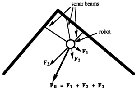
4.5 Obstacle Repulsive Force... 50
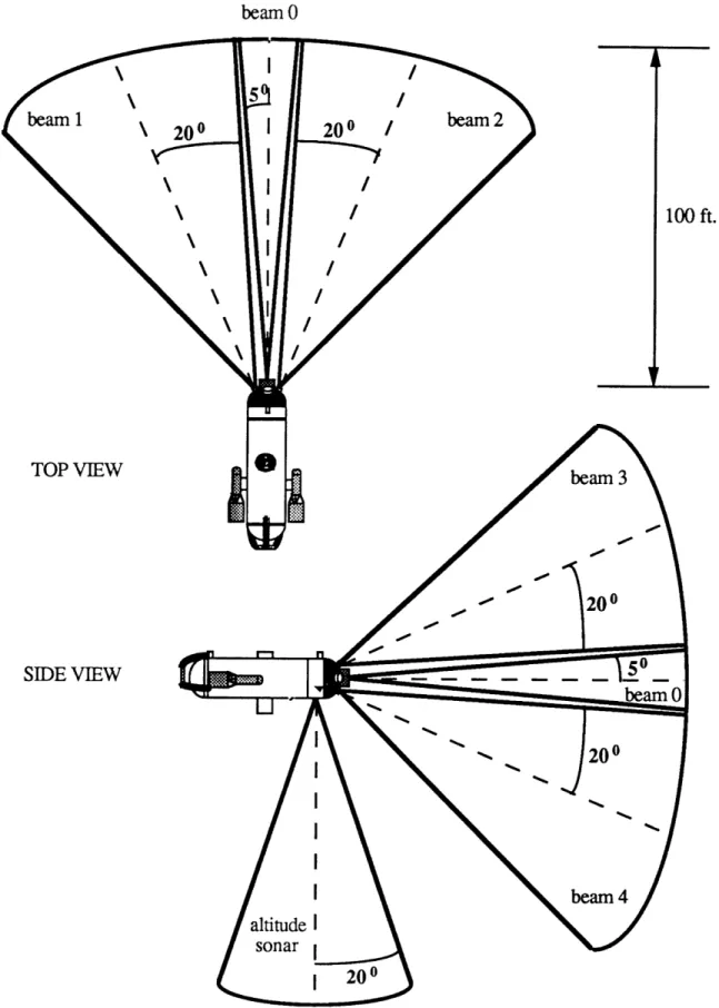
4.6 Proposed Sonar Configuration for AUV... 51
4.7 Obstructing Obstacles... ... 54
4.8 Lateral Collision Avoidance... 58
4.9 Collision Avoidance Module Flowchart ... 60
4.10 Vertical Collision Avoidance... 61
4.11 Waypoint Acquisition Module Flowchart... 65
4.12 Waypoint Trajectory Constraint... 68
5.1 Task Scheduling... 80
5.2 Modified Waypoint Acquisition Module Flowchart... 85
6.1 Depth Envelope Test: t = 6 seconds... 92
6.2 Depth Envelope Test: t = 14 seconds... 92
6.3 Depth Envelope Test: t = 29 seconds... 93
6.4 Depth Envelope Test: t = 55 seconds... 93
6.5 Collision Avoidance Test: Single Obstacle... 96
6.6 Collision Avoidance Test: Three Obstacles Case 1... 96
6.7 Collision Avoidance Test: Three Obstacles Case 2... 97
6.8 Waypoint Acquisition Module Test... 98
6.9 Reflexive Control without Waypoint Planner Case la... 101
6.10 Reflexive Control without Waypoint Planner Case 2a... 101
6.11 Reflexive Control without Waypoint Planner Case 3a... 102
6.12 Reflexive Control with Waypoint Planner Case 2b t = 25 seconds.. 105
6.13 Reflexive Control with Waypoint Planner Case 2b t = 70 seconds.. 106
6.14 Reflexive Control with Waypoint Planner Case 3b... 106
6.15 AUV In-Water Autonomous Test Set-up... 108
6.16 Heading Control Level... 113
6.17 Velocity Control Level... 113
6.18 Depth Control Level... 114
6.19 Commanded Depth vs. Sensed Depth... 116
6.20 Commanded Heading vs. Sensed Heading... 116
6.21 Commanded Velocity vs. Sensed Velocity... 117
[This page left intentionally blank]
CHAPTER
1
INTRODUCTION
In recent years there has been a growing interest in the development of planning architectures for autonomous underwater vehicles (AUVs). The potential application for AUVs are widespread, including such tasks as: inspection and repair of underwater structures, monitoring and detection of pollution or chemical leaks, or mapping underwater terrain. Fundamental to almost all AUV applications is the capability to successfully navigate from one position to another while avoiding obstacles and underwater terrain.
This thesis describes the design and implementation of a planning architecture to successfully navigate an AUV from a starting location to task location while avoiding obstacles and underwater terrain. The design is based on a layered control architecture originally proposed by Brook's [1] for use on autonomous land robots. The design has been implemented and tested using a small AUV, constructed by the M.I.T. Sea Grant College Program.
1.1 PROBLEM STATEMENT
The design of a planning architecture for an autonomous underwater vehicle is faced with the problem of demonstrating intelligent robotic behavior in real-world situations. For a mobile robot or AUV, intelligent robotic behavior consists of reacting to the environment as well as, or better than, a human operator. Examples of intelligent behavior for an AUV include: avoiding collisions with obstacles in the environment,
manuevering to a goal position, remembering the position of obstacles, and performing tasks such as docking with an underwater platform or repairing a pipeline.
The range of intelligent behaviors investigated in this thesis is limited to: maintaining the vehicle within a safe operating region; avoiding collisions with underwater terrain and obstacles; acquiring a goal position; and generating intelligent trajectories to goal positions.
These intelligent behaviors are proposed for implementation on a real AUV with the following constraints: the sensing capability of the vehicle is limited to 5 sonar range sensors which cover a 90 degree cone eminating from the nose of the AUV, data processing is performed by a single 68000 based microprocessor, and the vehicle has specific performance limitations which require consideration of the vehicle dynamic capabilities in the planning architecture.
The constraints imposed by the vehicle's dynamic performance require that the planning architecture generate real-time responses to environmental conditions which are only partially known due to limited sonar coverage. In addition the dynamics of the vehicle need to be addressed by the planning architecture to insure mission success. Of primary concern is the ability of the AUV to react to real-time events.
1.2
SEA SQUIRT VEHICLE
Since January 1988, the C.S. Draper Laboratory (CSDL) and M.I.T. Sea Grant College Program have been constructing the "Sea Squirt", a small autonomous underwater vehicle. The objective of this effort is to demonstrate intelligent robotic behavior on a small low-cost submersible. To do this, work has been in progress on the vehicle control system, the planning architecture, and the vehicle hardware integration.
The Sea Squirt AUV was designed to have a complement of sensors which include: heading, depth, velocity, yaw-rate, pitch, and roll sensors. In addition to the vehicle state
2 40.
sensors, a navigation system was designed to provide the vehicle with a three-dimensional position in the underwater environment, and a forward sonar array, consisting of five sonar beams mounted on the AUV forward dome, yields range information to obstacles in the environment. The integration of hardware into the AUV has been completed, with the exception of the mounting of the navigation system and the installation of the complete forward sonar array. Currently the forward sonar array consists of a single forward pointing sonar. Additional sonar units are to be installed in the near future.
1.3 PLANNING ARCHITECTURE
The planning architecture generates control commands to control the trajectory of an AUV to meet mission requirements in response to the state of the environment. A primary requirement of a planning architecture for an AUV is that the architecture respond to changing underwater conditions in real-time. Planning architectures developed for land-based robots have typically applied model-land-based planning algorithms, in which a model of the environment is constructed from sensor data and is used explicitly to generate control commands. Because they require computationally intensive algorithms, model-based planning architectures developed for land-based robots are limited in their ability to generate control commands in real-time. For this reason an alternative planning architecture was selected for implementation.
A reflexive control architecture has been developed and implemented on a small AUV. The architecture consists of a hierarchical set of software modules which independently generate control commands to control the trajectory of the AUV. The individual modules in the reflexive control architecture generate control commands directly from the current sensor data, without constructing a world model, and are able to generate control commands in real-time. The reflexive control architecture is a derivative of the layered control architecture proposed by Brook's[ ].
A reflexive control architecture approach was selected for three reasons: (1) the architecture generates control commands in real-time; (2) additional modules can be added to the architecture without modifying the existing modules; and (3) the reflexive control architecture modules provide mission robustness.
One disadvantage of both the layered control and reflexive control architectures is that they can often generate suboptimal trajectories. To solve this problem, a model-based trajectory generation algorithm has been developed, which generates an optimal reference trajectory. The model-based trajectory generation algorithm has been integrated with the reflexive control architecture in such a way that it does not impede the real-time operation of the reflexive control architecture. The model-based trajectory generator working in conjunction with the reflexive control architecture can produce more efficient trajectories than could be generated by the reflexive control architecture alone..
1.4 ORGANIZATION
The thesis is divided into seven chapters. The application proposed for testing the reflexive control architecture is discussed in Chapter 2. The planning architecture is discussed in more detail in Chapter 3. The benefits of layered control and how reflexive control is a logical derivative of layered control are described. The design of the individual modules in the reflexive control architecture is discussed in Chapter 4. Chapter 5 describes the implementation of the planning architecture to the AUV and discusses the modifications required to accomodate the lack of a navigation system on the AUV. Simulation and in-water test results are presented in Chapter 6, which show the ability of the AUV to avoid collisions while manuevering around the M.I.T. Alumni pool. Simulation results are also presented which demonstrate the capabilities of the AUV when configured with a five beam forward sonar array and a navigation system. The five beam sonar array and the navigation
system are scheduled to be integrated into the AUV in the near future. Conclusions and recommendations are discussed in Chapter 7.
CHAPTER
2
APPLICATION
The design of a planning architecture for a robotic vehicle depends heavily on the particular vehicle application. The sensing capability, processing power, and vehicle dynamics all shape the design of a planning architecture. The type and number of sensors affect the design of the planning algorithms and define what type of sensor processing is necessary. The onboard processing power limits the extent of intensive processing, which affects the selection of a planning architecture. The dynamic capabilities and limitations of the particular application also shape the design of a planning architecture. For this reason, the AUV application is presented in Chapter 2 in order to define the sensing, processing, and dynamic constraints which led to the selection of a planning architecture for the AUV.
2.1 VEHICLE DESCRIPTION
The autonomous underwater vehicle (AUV) constructed by CSDL and the M.I.T. Sea Grant Program is a modified Benthos Mark II Mini-Rover. The Mini-Rover is a commercially marketed submersible intended for tethered remote operation. To date it's principal use has been to inspect offshore oil rigs using a camera mounted in the nose. In it's original configuration the vehicle is capable of diving to depths of 200 feet and cruising at 2.5 knots. The AUV has been modified to include a complement of autonomous sensors and an onboard microprocessor.
2.1.1 HULL
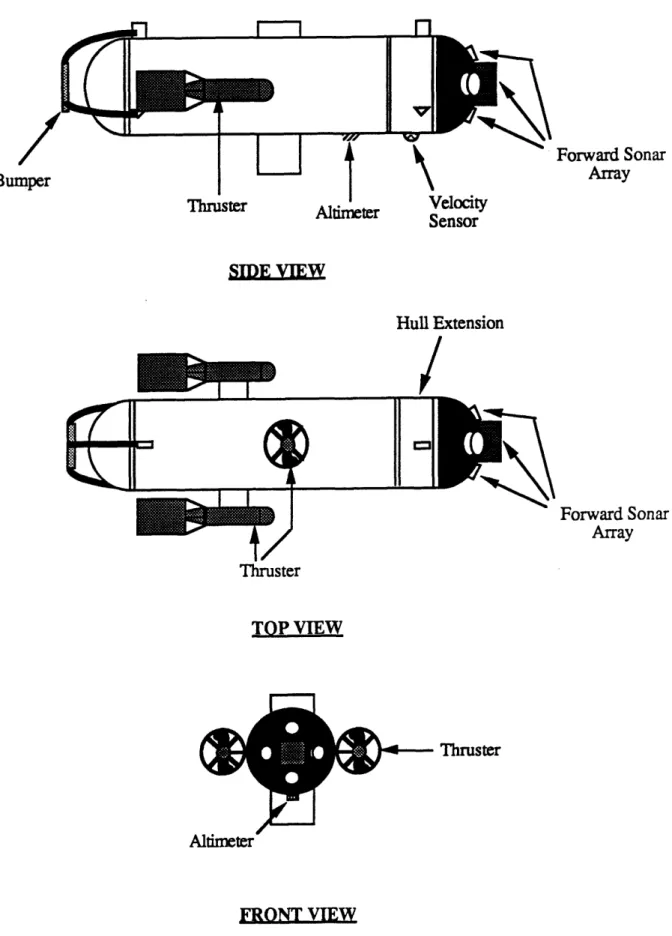
The AUV's hull is 34 inches long and 8.7 inches in diameter. The main hull consists of a cylindrical center section capped with hemispherical domes at each end, as shown in Figure 2.1. A 4.5 inch hull extension has been added between the forward dome and the main hull to accomodate additional electronics. The main hull, hull extension, and forward dome are constructed of aluminum, while the aft dome is plexiglass. The plexiglass dome was originally used as a window for an internally mounted video camera. It is currently used to display a set of LED's that describe the vehicle's operating status. When fully loaded, the AUV weighs 62 lbs. and displaces 63 lbs. of water, making the vehicle slightly positively buoyant. The AUV was purposely designed to be positively buoyant to insure that the AUV will float to the surface in the event of a loss of power.
Forward Sonar Array inruster Altimeter *w•oyv
Sensor Hull Extension Forward Sonar Array - Thruster Altimeter
FRONT VIEW
Figure 2.1: Sea Squirt Autonomous Underwater Vehicle Bui
Thruster
TOP VIEW
r---l
/K--2.1.2 PROPULSION
The AUV is propelled by three thrusters. Two horizontal thrusters provide speed and heading control and a vertical thruster provides depth control. As shown in Figure 2.1, the vertical thruster passes through the hull and allows the vehicle to hover and change depth without lateral motion. The vertical thruster is mounted in the center of the
AUV in a cylindrical tube which passes through the main hull. The horizontal thrusters are
mounted on either side of the AUV towards the stem. All of the thrusters provide thrust in both forward and reverse directions allowing the vehicle to perform complex manuevers such as hovering, backing up, and zero velocity turns. Each thruster is capable of generating up to 7 lbs. of static thrust. In it's current configuration the AUV does not use any active control surfaces.
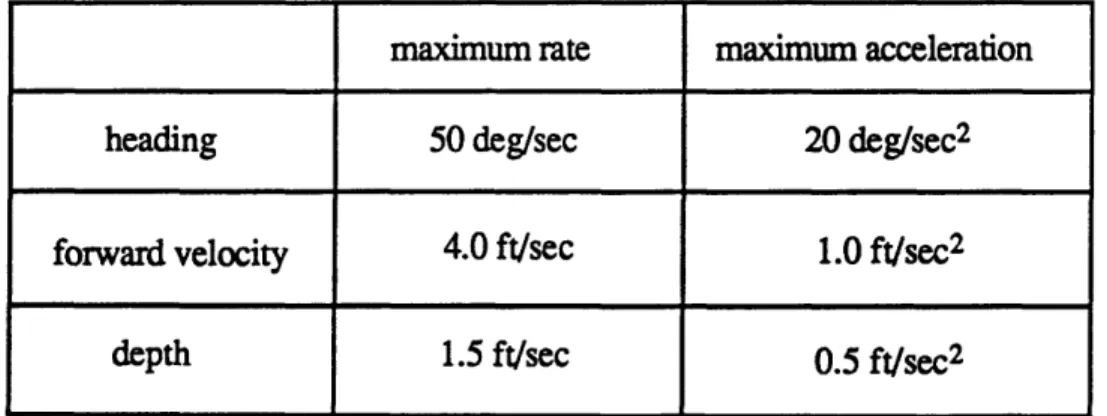
Power to the thrusters is provided by 32 silver-zinc batteries that provide from 2 to 16 hours of power depending on the AUV's operating speed. Silver-zinc batteries were selected because of their high power to density ratio, allowing them to fit inside the main hull of the AUV. The performance characteristics of the AUV, in it's modified configuration, are listed in Table 1.
maximum rate maximum acceleration
heading 50 deg/sec 20 deg/sec2
forward velocity 4.0 ft/sec 1.0 ft/sec2
depth 1.5 ft/sec 0.5 ft/sec2
2.1.3 ONBOARD PROCESSOR
To perform autonomously, the AUV needs an onboard computer. The computer system that was selected for the AUV consists of two boards, a GESPAC SBS-6 68000
CPU board and a GESPAC ADA-1 I/O interface board. The boards are single height
Eurocards, which were selected because they could fit into narrow inside diameter of the main hull.
The CPU board consists of a Motorola 68000 CPU operating at a clock speed of 8 MHz with 256K of RAM, 256K of EPROM, 2 serial communication ports, 2 8-bit parallel ports, and three counter/timers. The SBS-6 board does not contain a math coprocessor chip.
The I/O interface board contains 16 single-ended analog inputs and 4 analog outputs. The 16 analog inputs are converted to 10-bit digital values by the A/D convertor on the board. The A/D convertor is multiplexed between the individual inputs. The A/D input lines are currently used to digitize the sensor data from all sensor subsystems on the
AUV. Three of the D/A output lines are used to generate analog signals for the thruster
motor controllers.
The onboard computer uses the OS-9 real-time operating system. This operating system supports both multi-tasking and interrupt operations. These features are used to integrate the planning and control functions onto a single CPU. At the present time the software runs using a software generated interrupt every 200 ms. The sensors are read and the control software is updated and the remaining CPU time is then available for the planning software.
To date the 68000 board has provided sufficient throughput to implement the planning and control software at a frequency of 5 Hz., but the current board is quickly reaching the limit of it's capabilities due to the lack of a math coprocessor. To overcome
this difficulty, in the near future, a GESPAC MPU-20 68020 board will replace the existing 68000 board. The new board consists of a Motorola 68020 32-bit processor running at 16 MHz with a 68881 math coprocessor chip. The board also contains 512K of RAM and 256K of EPROM. The new board should boost the speed of software operations by a factor of -20 times.
2.1.4 SENSORS
In it's original configuration, the only sensor onboard the vehicle was a video camera used by a surface operator to manuever the vehicle. Commands to the vehicle were sent via a tether communication link. For autonomous operation, a large number of sensors are required, both for planning and control.
In it's current configuration, the AUV's onboard sensors include: a fluxgate electronic compass, a pressure transducer for measuring depth, a speed sensor, pitch and roll inclinometers; a yaw rate gyro; a high frequency sonar pointing out the nose of the
AUV, and an altitude sonar. The sensors can be thought of as falling into one of 5
categories: position sensors; position rate sensors; attitude sensors; attitude rate sensors; and imaging sensors.
Position Sensors
The position sensors consist of a Sensym pressure tranducer which measures the AUV's depth. It's current range is 0 to 30 feet. The range of this sensor can be increased, however for initial tests the 30 foot range is sufficient for testing in the M.I.T. Alumni pool and the Charles River. Altitude above underwater terrain is sensed by a downward looking Datamarine sonar. This sonar unit was originally configured as a boat depth sounder and has been converted for operation on the AUV. The altimeter returns altitudes from 2 to
100 feet. A navigation system for the AUV has been developed and tested but has not yet
been integrated onto the AUV. The navigation system consists of pinger and hydrophone mounted on the AUV which interrogate three transponders positioned at fixed locations. The range to each transponder is used to triangulate the AUV's three-dimensional position.
The navigation system has been tested in Boston harbor and has an accuracy in position measurement of approximately 1 meter.[2] The navigation system will be integrated onto the AUV when an external container has been constructed.
Position Rate Sensors
The only position rate sensor onboard the vehicle is a Datamarine speed sensor.
The speed sensor consists of a paddle wheel which is turned by the water flow past the
AUV hull. The sensor produces a voltage proportional to the water velocity. The
Datamarine speed sensor has a significant deadband between 0 and 1 ft/sec velocities and is
extremely noisy.
Attitude Sensors
The vehicle has three attitude sensors consisting of an electronic compass, and pitch and roll inclinometers. The compass is a low-cost (< $40.00) Zemco electronic compass designed for use in automobiles. The compass measures the Earth's magnetic field in two directions and outputs a voltage proportional to the compass heading. The compass sensor is not gimballed, and thus is affected by the pitch and roll of the AUV, which can cause the magnetic field measurement to become skewed. The variations in compass heading are on the order of 1:1; 1 degree of pitch or roll causes the compass heading to be in error by 1 degree. The Spectron pitch and roll inclinometers are electrolytic sensors which are capable of measuring pitch and roll angles up to 45.0 degrees.
Attitude Rate Sensors
The only attitude rate sensor on the AUV is a Gorham Model Products model helicopter gyro. The gyro was designed for model helicopters as a stability aid. It has been installed on the AUV as a yaw rate sensor. The yaw rate gyro has significant noise and drift problems but has been corrected by a filter and bias corrector implemented in software.
Imagine Sensors
The imaging sensors consist of sensors which the planning architecture uses to sense the state of the environment. Currently the AUV uses a Mesotech 807 narrow beam sonar to detect underwater obstacles. The Mesotech sonar operates at a frequency of 200 KHz and has a beamwidth of 10 degrees. The sonar is mounted through the aluminum forward dome of the AUV and points directly forward. An additional complement of four Datamarine sonars, positioned around the Mesotech sonar is to be integrated onto the AUV in the near future. The configuration of the additional sonar beams will be discussed in Chapter 4.
The limited sensing capability of the AUV imposes serious constraints on any planning architecture. The challenge is to select and implement a planning approach which can overcome the limited sensory capability of the AUV.
2.2
AUTONOMOUS MISSION
A nominal mission was selected for the AUV to provide a starting point from which
additional capabilities could be added. The nominal mission for the AUV consists of traversing an unknown underwater environment to a specified position. This nominal mission was selected because it includes the fundamental problems that an AUV must address when operating autonomously. These problems are: maintaining a safe operational depth; avoiding collisions with underwater obstacles and terrain; and generating an efficient trajectory to a specified position.
To perform this mission the AUV must have an onboard system which generates position information either in latitude and longitude or in distance from a fixed reference. Estimating the AUV position through landmark recognition is one possibility to determine position, however for initial implementation an acoustic transponder array will be used to actively localize the position of the AUV. The AUV interrogates the transponders to return range information and triangulates it's position relative to the fixed transponder array. A goal position is specified relative to the fixed transponder array. For the initial mission, the goal position is specified as a pre-mission input. Eventually it is expected that the goal locations will be determined by the planning system itself.
It is also necessary for the AUV to measure the positions of underwater terrain and obstacles. In it's current configuration the AUV relies solely on sonar range data to determine the range to obstacles in the environment. By appropriately configuring multiple sonar beams on the AUV, an approximate bearing to obstacles can also be obtained.
Requirements for this mission are to reach the goal position using an efficient trajectory while maintaining a safe operational depth and avoiding collisions with underwater terrain and obstacles. This mission is realizable for a small autonomous
underwater vehicle with limited sensing capability, yet it is sufficently challenging to test the performance of the planning architecture. A diagram of this mission is shown in Figure 2.2. obstacles
O
0
O
O
goal position
terrain AUV2.3 SYSTEM ARCHITECTURE
A system architecture was developed for the AUV to integrate the control and
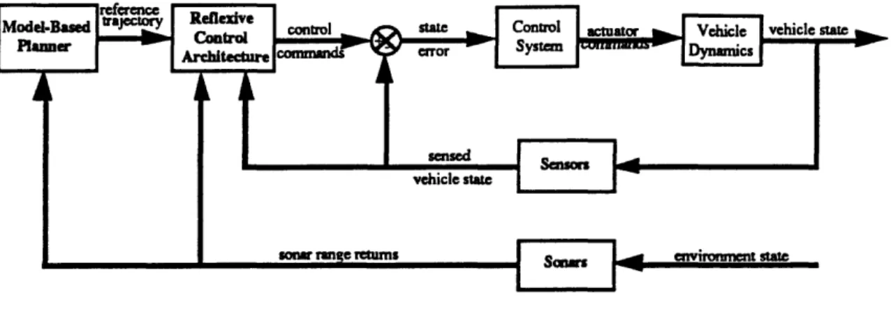
planning software onto the AUV microprocessor. The system architecture consists of an inner closed-loop control system and an outer trajectory planning loop. The planning loop consists of a reflexive control architecture which generates a desired vehicle state based on the sensed state and the sonar range returns. The inner loop consists of a closed-loop control system which generates actuator commands based on the desired vehicle state obtained from the planning loop. The system architecture is depicted in Figure 2.3.
The figure shows the feedback of the vehicle state to both the control system inner loop and the outer planning loop. The planning loop has the additional feedback of sonar range returns to obstacles in the environment. Also the vehicle state fedback to the planning contains the vehicle position as sensed by the navigation system. This vehicle state is not used by the control system. The next two sections describe how the planning and control loops interact to produce the desired vehicle trajectory.
Figure 2.3: System Architecture
Because the dynamics of the AUV are highly non-linear and poorly known, direct open-loop control of the thruster commands would result in poor performance or instability. For this reason a vehicle control system, based on sliding mode control theory, was developed which drives AUV to the desired state. The controllable vehicle states for the AUV are; heading, forward velocity, and depth.
2.3.1 CONTROL
The AUV maintains stability and control through the use of a vertical and two horizontal thrusters. This set of effectors enables the AUV to perform more complicated manuevers then could be achieved by using stem and bowplanes. Controlling the AUV in these circumstances is a challenging task.
The control system that was selected for the AUV is a sliding mode controller[3]. Sliding mode control is a non-linear control methodology, which has several advantageous features over classical approaches. First, sliding mode control provides stability guarantees and performance guarantees for vehicle dynamics which are highly non-linear and which may be poorly known. Second, sliding mode control is a tracking controller which tracks a commanded state trajectory. Thus transient responses to a change in the commanded state
are tracked along well defined trajectories from the initial state to the final commanded state. This information is very useful for the planning loop to determine the achievability of a
state transition in a given time interval.
The sliding mode controller implemented on the AUV controls the heading and depth states of the AUV. Currently the velocity loop of the AUV is commanded open-loop due to the poor performance of the velocity sensor at low speeds. The sliding mode control system has been tested and verified in both the Charles River and the M.I.T. alumni pool. Of particular interest to the planning architecture are the dynamics of the heading and depth modes. The sliding mode controller has the ability to track depth state changes with an acceleration of 0.2 ft/sec2 and a maximum depth rate of 1.0 ft/sec. Heading state changes can be tracked with an acceleration of 5.0 deg/sec2 and a maximum rate of 15 deg/sec. These parameters are used by the planning architecture to insure that plans are not generated which are inconsistent with the dynamic capabilities of the AUV.
2.3.2 REFLEXIVE CONTROL ARCHITECTURE
The reflexive control architecture shown as the outer loop in Figure 2.3 is responsible for generating control commands for the control system in response to the current vehicle state and the environment state as sensed by the sonar range sensors. The requirements on the reflexive control architecture are to generate control commands in real-time which accomplish the mission objectives. Real-real-time operation can be defined as being able to generate state commands in time to respond to a dynamic environment. Typically this means generating control commands to changes in the environment on the order of tenths of seconds.
A derivative of a layered control architecture, called reflexive control, was selected
for implementation because of several features. First is the ability of the reflexive control architecture to generate control commands in real-time. Second, the reflexive control architecture has a structure which can be constructed incrementally, aiding in both the development and testing of the architecture and also in the extension of the architecture to accomplish tasks of increasing complexity. In addition, the reflexive architecture provides built-in mission robustness.
2.3.2 MODEL-BASED PLANNER
A model-based planner was integrated into the system architecture as shown in Figure 2.3. The model-based planner constructs a world-model consisting of the positions of obstacles sensed in the environment by using the sonar range data from the forward sonar array. The model-based planner derives it's name from the model which the planner uses to generate output. The output of the model-based planner shown in Figure 2.3 is a reference trajectory. The reference trajectory consists of series of positions which guide the trajectory of the AUV. The reference trajectory is input to the reflexive control architecture which uses the reference trajectory to improve the efficiency of the final AUV trajectory.
CHAPTER
3
REFLEXIVE CONTROL ARCHITECTURE
The reflexive control architecture was designed to be easily extendible and reconfigurable, provide built-in robustness, operate in real-time in a three-dimensional environment, and demonstrate intelligent behavior in real-world situations. The reflexive control architecture is a derivative of Brook's layered control architecture. Thus in order to understand the motivation and benefits of the planning approach used, the layered control architecture is first discussed in Section 3.1. Section 3.2 details the differences between reflexive control and layered control. Section 3.3 explains how a model-based planning capability can be integrated into the existing reflexive control architecture without affecting the real-time performance of the system.
3.1
LAYERED CONTROL
To understand the motivation for selecting layered control as the approach to autonomous vehicle planning, it is first necessary to understand the traditional approach which has been applied to land-based robotic vehicles. Traditional model-based planning architectures rely on the formulation of a world-model which is used to plan the vehicle's actions. A world model is defined as a data structure that stores sensor and a priori information, about the state of the vehicle and the environment. As a robotic vehicle traverses the environment, a world model can be constructed which incorporates newly sensed information into the model. The actions of the robotic vehicle are determined by algorithms which use the world model explicitly.
Many model-based planners have been successfully used on land-based robots such as the CMU Terregator.[4] This outdoor mobile robot uses a sonar array to sense the location of obstacles which are placed into a two-dimensional world map. From this world map the robot is able to plan obstacle free paths using an A* search algorithm.[5] The path can be optimized for any desired criteria, however, depending on the sensors, size of the world model, and the computational power available, a model-based planning architecture can take on the order of tens of seconds to generate a response to a change in the environment. This may be acceptable for vehicles which can stop while planning, but it is likely to be ineffective for planning the actions of the AUV.
An alternative to the model-based planning approach has been proposed by Professor Rodney Brook's of the M.I.T. Artificial Intelligence Laboratory. Brooks proposes to decompose the planning architecture into parallel task-achieving behaviors as shown in Figure 3.1. Each task-achieving behavior maps sensor data directly to actuator commands without using a world model. Each behavior module runs independently, generating actuator commands that are appropriate for the behavior being implemented in the given situation. Conflicting actuator commands are handled by a simple arbitration algorithm. Brook's calls such an architecture a layered control architecture.
The central idea behind layered control is that intelligent robotic behavior can be achieved through the interaction of independent, achieving behaviors. Each task-achieving behavior is implemented as an independent module of the layered control architecture. Thus task-achieving behaviors can be built up incrementally to increase the intelligent capabilities of a robotic vehicle. An example of layered control architecture task-achieving behaviors is shown in Figure 3.2. The task-task-achieving behaviors shown in Figure 3.2 consist of:
(1) avoid objects - This behavior module enables the robotic vehicle to avoid collisions with stationary objects and to flee from moving objects. The robotic vehicle will remain stationary if no objects come within the avoidance distance.
(2) wander - The wander behavior generates a random direction for the robotic vehicle to travel. The wander behavior enables the robot to move about the environment in a random manner.
(3) explore - The explore behavior selects an area of interest in the environment such as the far corner of a room. This behavior demostrates a higher level of intelligence than the wander behavior.
(4) identify objects - The identify objects behavior seeks to classify objects in the environment. This level of behavior enables the robotic vehicle to react differently to objects based on their classification.
(5) reason about the behavior of objects - This behavior observes identified objects and classifies their behavior. This behavior would modify the actions of the robotic vehicle based on the expected behavior of objects in the environment.
reason about the behavior of objects
sensors identfy objects actuators
explore wander avoid objects
Figure 3.2: Task-achieving Behaviors
The task-achieving behaviors described above, demonstrate the increasing intelligence level of behavior modules as they are added to the top of the layered control architecture. At the lowest level of behavior, the robotic vehicle is able to manuever away from objects which approach too closely, while at the highest level the robotic vehicle is capable of responding to an object based on the object's expected behavior. Brook's proposes that such levels of intelligence can be constructed incrementally.
When more than one of the behavior modules simultaneously attempts to command the vehicle's actuators, an arbitration algorithm is required to determine which of the modules should take control. Brook's layered control architecture handles these conflicts through the use of subsumption, in which one behavior is able to subsume or override the output of another behavior for a specified period of time. Brook's motivation for this approach was to allow module's with a more intelligent response, to subsume control from
modules with less intelligence. The ordering of the modules shown in Figure 3.2 shows that the more intelligent behavior modules are positioned above the less intelligent behavior modules. Therefore the subsumption arbitration used in a layered control architecture enables a behavior module to subsume the output of behavior module's at a lower level.
The subsumption arbitration operator is shown in Figure 3.3. The S denotes that the input from above, Vi+1, is to subsume the input from the left, Vi. The subscript i signifies that the command is from level i in the layered control architecture. The number below the S signifies the amount of time that command Vi+1 will subsume command Vi. When a module has no command it outputs 0. When qi+1 is 0, Vi is not subsumed and Vi is passed as the output. When Vli+1 0, Nfi+l is passed as the output.
I VC: if Vi+l
10
Vi+1 : if Vji+10
Figure 3.3: Subsumption Arbitration Operator
There are several advantages in using a layered control approach. The primary advantage is that new intelligent behaviors can be added to the vehicle incrementally without having to modify the behaviors already in place. A second advantage is that since the modules are independent, the modules can be implemented using a parallel computer architecture.
There are also disadvantages in using a layered control architecture approach. Although additional behavior modules can be added to the layered control architecture, the subsumption arbitration algorithm introduces a complication in the development of higher levels of behavior. Because a higher level module subsumes the output of all lower level modules, a higher level module is required to generate commands which satisfy the requirements of the lower levels, in addition to adding the intelligence of a higher level behavior. For example, the zeroth level and first level of the layered control architecture
developed by Brook's [6] for the AI Lab robot Allen, consist of an "avoid objects" behavior and a "wander" behavior. The wander behavior is positioned above the avoid objects behavior as shown in Figure 3.4. The wander behavior subsumes the output of the avoid objects behavior for a period of 20 seconds each time the wander behavior generates a random heading command. Because the wander behavior subsumes the output of the avoid objects behavior, the wander behavior module must also contain the algorithms which avoid objects. Otherwise the wander behavior would generate random heading directions which may collide with an object. Subsequent behaviors added to the layered control architecture must also address the requirement of avoiding objects.
Figure 3.4: Two Level Layered Control Example
Using the layered control architecture, it becomes cumbersome to develop more intelligent levels of behavior which must perform behaviors already developed in lower level modules. An alternative approach which addresses this problem by modifying the subsumption arbitration algorithm is now proposed.
3.2 REFLEXIVE CONTROL
An alternative approach to layered control architectures has been developed that uses an alternative arbitration algorithm. It is called a reflexive control architecture. The primary difference which distinguishes the reflexive control architecture from a layered control architecture is the arbitration algorithm employed to determine which level should take control of the AUV. The subsumption arbitration algorithm for the layered control architecture enables behavior modules at higher levels in the architecture to subsume control over behavior module's which are positioned at a lower level in the layered control architecture. The subsumption arbitration algorithm imposes constraints on the behavior modules at higher level positions to generate commands which incorporate the capabilities of the behavior modules at lower level positions.
The reflexive control architecture solves this problem by using an alternative arbitration algorithm called reflexive arbitration. Instead of allowing higher level modules to subsume the output of lower level modules, the reflexive arbitration algorithm enables modules positioned at a lower level in the reflexive control architecture to take control from modules positioned at higher levels. A module positioned above a lower module will gain control of the reflexive architecture output only when the lower module has generated no output.
The reflexive arbitration operator is shown in Figure 3.5. The input Vi+1 is defined as a command from level i+l in the reflexive control architecture. Similarily, Vi is a command from level i in the reflexive control architecture. The reflexive arbitration operator enables the lowest level module with a command to override the higher level module. A higher level module can control the reflexive arbitration output only when the lower level command is 0. A module outputs 0 when it has no command to implement.
WVi+i
{ VCi+1 if Vi= 0 IV : if l# L i'
0
Figure 3.5: Reflexive Arbitration Operator
The modules in the reflexive control architecture generate output only when the module's activation condition has been triggered. Thus if a module generates commands which do not trigger the activation conditions of module's positioned at lower levels, the module gains control of the reflexive control architecture output.
Thus a higher level module can gain control of a control command only when all lower level modules have no output for that control command. For example, the two level layered control architecture described in the previous section is reformulated into the reflexive control architecture shown in Figure 3.6. The reflexive control architecture shown consists of the avoid objects and wander modules, but the subsumption arbitration has been replaced with a reflexive arbitration operator. Thus in the reflexive control architecture, the avoid objects module overrides the output of the wander module when an object triggers the avoid objects activation condition. The wander module can then generate a random heading command without including the additional computation involved in the avoid objects module. Should the wander module generate a heading which will lead to a collision, the avoid objects module overrides the wander module's heading to avoid the collision. Once the collision has been avoided, the avoid objects module outputs 0, and
the wander module is again able to implement a random heading command. This example illustrates how the reflexive control architecture enables module's at higher levels in the reflexive control architecture to ignore the details of low level requirements such as avoiding objects. Thus the reflexive control architecture avoids the duplication of algorithms previously developed in the lower level modules.
Figure 3.6: Two Level Reflexive Control Example
An additional benefit of the reflexive control architecture is that it adds robustness to the overall behavior of the AUV. A higher level module's commands are corrected by the lower level module commands when the higher level module's commands violate a mission requirement. For example, the wander module commands the vehicle to move in a direction 0, however an object is located along the direction 0. The avoid objects module commands a deviation in the vehicle trajectory so that the object is avoided. The avoid objects module command overrides the wander module's command using the reflexive arbitration operator. The avoid objects module in the layered control example cannot override the wander module. Once the object is avoided the wander module is able to command a new random heading.
The reflexive control architecture consists of multiple reflexive software modules which independently generate control commands for the vehicle control system to track. The reflexive control architecture is shown in Figure 3.7. The arbitration points are specified by the circled R and enable the control commands of the lower level module to override the control commands of the higher level module.
The figure shows each reflexive module generating a control command vector. A control command vector is defined as a vector which consists of a set of control commands which the vehicle control system requires as input.
sensors 7eLeive Module n Reflexive Module 2 i module n control command vector module 2 control command vector
Reflexive module 1 control vehicle contro
mpI Module 1 command vector command vect
Figure 3.7: Reflexive Control Architecture
The control command vector generated by the reflexive control architecture is the result of a reflexive arbitration algorithm applied to the multiple control command vectors issued by the individual reflexive modules. The arbitration function is denoted by the R in Figure 3.7 and enables the lowest level reflexive module to have control of the commands specified in the control command vector. A higher level reflexive module will gain control of a control command only when all lower level modules have no output for that control command. When a module has no output for a state it outputs 0.
*
Each module in the reflexive hierarchy generates a control command vector which consists of a vector of commands that is formulated to accomplish the module's individual task. A module's task is a small subset of the overall mission tasks. Examples of tasks for an AUV are to avoid collisions, maintain safe operational depth, and acquire a goal position.
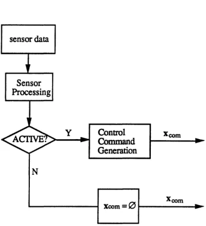
A reflexive module generates a control command vector only when it's activation condition has been triggered, as shown in Figure 3.8. The current sensor data is read as input and is used to formulate an activation condition. Examples of activation conditions are dynamic thresholds on sensor data, or the presence or absence of a portion of the sensor data. Depending on the outcome of the activation condition test, a module either generates a desired state vector or outputs no command. When the module is active a desired state vector is generated, when not active the module outputs
0,
designating that the module does not require an action, thus freeing a higher level module to gain control of the desired state vector.Xeom
Figure 3.8: Reflexive Module Flowchart
It is important to note that a module need not specify the entire control command vector when activated. A module which requires only that a subset of the control command vector be implemented, specifies only that subset of the control command vector. This aspect of the reflexive control architecture adds flexibility to the interaction between module levels.
3.3 MODEL-BASED PLANNING
The reflexive control and layered control architecture both generate commands based on current sensor data without building a world model. The reflexive control and layered control architectures are capable of responding to a changing environment much
faster than model-based planners. However, the resultant trajectory may not be an efficient one. This is due to the lack of a global view of the environment which could be provided by a world model. What is needed is the ability to plan a globally efficient trajectory and still retain the ability to respond to real-time events. This was accomplished by the development of a model-based planning module called the waypoint planner. The waypoint planner module generates a reference trajectory which the reflexive control architecture uses to guide the AUV to a goal location. The waypoint planner module generates a waypoint plan consisting of set of waypoint positions which guide the AUV to the goal position along an intelligent trajectory. The waypoint plan is downloaded to the reflexive control architecture as shown in Figure 3.9. The reflexive control architecture will follow the waypoint plan as long as the waypoint plan does not violate any of the mission requirements. Violation of a mission requirement causes a reflexive module to activate and the trajectory of the AUV is corrected by the reflexive module.
The waypoint planner constructs a model of the world by incorporating sonar range data into a finite element grid of the underwater environment. The grid is fixed with respect to the environment and sonar data is incorporated by determining the position of an obstacle from the AUV position and the geometry of the sonar beam. The state of each element in the grid consists of a probability of occupation determined by applying Baye's Theorem to the current probability and the newly sensed information. This type of finite element grid is known as an occupancy grid[7]. From the finite element model of the environment, an optimal path is generated from the AUV's current location to a goal location. The reflexive control architecture response is not dependent on the generation of a waypoint plan in real-time. The reflexive control architecture continues to use only the current sensor data to generate control commands, but is aided by the global planning capability of the waypoint planner. The details of the waypoint planning module are discussed in Chapter 4.
CHAPTER
4
REFLEXIVE MODULE DESIGN
This chapter describes the design of the behavior modules that were developed for the reflexive control architecture. The design is based on the nominal sensor suite of the vehicle as described in Chapter 2. The modules were developed assuming that both the five beam sonar array and the navigation system are operational as discussed in Chapter 2. Revisions to the modules that are required to accomodate the current state of sensor integration of the AUV are discussed in Chapter 5. The reflexive modules are:
(1) Depth Envelope Module
The depth envelope module is responsible for maintaining the AUV within a region of safe operational depths. The motivation for the depth envelope module is to maintain vehicle safety.
Since the reflexive hierarchy allows any number of modules to command a desired depth it is important that the depth envelope module be at or near the bottom of the hierarchy. It is not required that the modules above the depth envelope module command depths which are within the depth envelope. Thus, higher level modules which might command a depth state outside of the depth envelope will be corrected by the depth envelope module's depth command.
(2) Collision Avoidance Module
The collision avoidance module is responsible for avoiding collisions with obstacles and underwater terrain. The collision avoidance module is designed to avoid collisions in real-time. Because it is possible that a higher level module may command the AUV into a possible collision, the collision avoidance module is required to activate and deviate the AUV trajectory to avoid a collision.
(3) Wavpoint Acquisition Module
The waypoint acquisition module allows the AUV to manuever to a goal location or locations. Multiple goal locations are referred to as waypoints. The waypoint acquisition module is responsible for acquiring the waypoint positions input to the module.
The waypoint acquisition module does not account for possible collisions when commanding the AUV to a waypoint position. The waypoint acquisition module is concerned only with acquiring a waypoint position and leaves trajectory deviations, due to obstacles and underwater terrain, to the other modules in the reflexive control architecture.
The modules are individually designed to accomplish a specific mission objective. For the goal acquisition mission, the objectives, in order of increasing intelligence, are: maintain safe operational depth, avoid collisions with underwater terrain and obstacles, and acquire a goal position or positions specified prior to the mission. These mission requirements are accomplished by the three modules outlined above in a reflexive control architecture.
The three level reflexive control architecture developed for the AUV is shown in Figure 4.1. The input to the reflexive modules consists of sensor data and a waypoint plan as shown in the figure. The sensor data includes both the AUV state data and the sonar range returns from the forward sonar array. The AUV state data consists of the measurements obtained from the onboard sensors described in Chapter 2 and includes: compass heading, position relative to fixed transponders, forward velocity, depth, yaw-rate, pitch and roll.
Figure 4.1: AUV Reflexive Control Architecture
The sonar range returns are included in the sensor input to the reflexive modules and include the returns from the 5 beam forward sonar array and the altitude return from the downward pointing sonar. The full sonar complement has not yet been implemented on the AUV. However, the reflexive control architecture has been designed to accept a general
multiple beam sonar input. Simulation results are presented in Chapter 6 using the five
beam forward sonar array, while in-water tests were conducted with only a single beam
forward sonar.
The waypoint plan is shown in Figure 4.1 as input to the waypoint acquisition
module. The waypoint plan is the mission plan for the AUV consisting of an ordered list
of waypoint positions that the AUV is required to acquire. The waypoint acquisition
module is responsible for acquiring the waypoint positions specified in the waypoint plan.
The waypoint plan can be specified prior to the mission as a set of waypoint
positions or as a single goal position to be acquired. The waypoint plan can also be
generated by a model-based planner module. Generation of the waypoint plan through a
model-based planning module is discussed in Section 4.4. Generating a waypoint plan
dynamically can improve the final trajectory of the AUV to a goal position as will be shown
in the results in Chapter 6.
The output of the reflexive control architecture is the AUV control command vector.
The control command vector consists of the set of desired vehicle states which the AUV
control system requires as input. The control command vector for the AUV is:
[com
Xcom = Zoom Ucom
where:
~com a heading command (deg)
zoom M depth command (ft)
The control command vector from the reflexive control architecture is the result of the reflexive arbitration operator applied to the control command vectors generated by the individual modules in the reflexive control architecture. The output of each module is a control command vector indexed by the module level as shown in Figure 4.1. The module control command vectors are passed through the reflexive arbitration operator as shown. The authority of modules in the reflexive control architecture is determined from the modules position in the architecture. For example, the depth envelope control command vector at level 1 will override any collision avoidance control command vector generated at level 2.
Modules at the lowest levels, such as the depth envelope module, are concerned with the safety of the AUV, and have the highest authority in controlling the AUV in situations in which the safety of the AUV is endangered. The collision avoidance module is also concerned with vehicle safety and is positioned above the depth envelope module. The collision avoidance module is positioned above the depth envelope module because the operational depth region requirement overrides the collision avoidance requirement. This does not mean that the AUV will collide with an obstacle before changing depth because the collision avoidance module generates commands which avoid a collision in the horizontal plane should the depth of the AUV be constrained by the depth envelope module.
Built on top of the vehicle safety modules are modules which are designed for mission success. The waypoint acquisition module is concerned only with mission success and is positioned above both the collision avoidance and depth envelope modules. This enables the vehicle safety modules, consisting of the depth envelope and collision avoidance modules, to control the AUV in situations in which the safety of the AUV is in danger. The waypoint acquisition module controls the AUV only when the safety of the AUV is not in danger.
The next three sections describe the problem statement, approach, and design for each of the three reflexive modules.
4.1 DEPTH ENVELOPE
4.1.1 PROBLEM STATEMENT
The reflexive control architecture must insure that the AUV operates at safe depths throughout the mission. The depth envelope module is responsible for keeping the AUV at a safe operational depth. There are three requirements that the depth envelope module must satisfy:
(1) Maximum Operational Depth
The AUV cannot operate safely below a certain depth. In it's current configuration, the maximum operational depth of the AUV is 200 feet. The depth envelope module must insure that the AUV stays above the maximum operational depth limit throughout the mission. Exceeding the maximum operational depth damages the thruster motors and endangers the safety of the AUV.
(2) Minimum Operational Altitude
The AUV needs to maintain a safe operating distance from the sea floor. This margin is referred to as the minimum operational altitude. The size of this margin will be a function of the AUV's manueverability and of the currents that might be encountered during operation. The depth envelope module must insure that the AUV maintains the minimum operational altitude above the bottom throughout the mission.
(3) Minimum Operational Depth
The forward sonar array that is mounted on the nose of the AUV is prone to generating false returns when the AUV is near the surface of the water. The sonar wavefront is reflected from the air/water interface and triggers the sonar, returning a false reading. The false reading may activate the collision avoidance module. Therefore, a minimum operational depth must be maintained to insure that the forward sonar array does not return surface reflections.
zmin z
F
hmin zmaxh
Figure 4.2: Operational Depth Region
To minimize deviations of the AUV trajectory outside the depth envelope, the depth envelope module must activate before the envelope is violated. The depth envelope module must account for the AUV depth dynamics in it's activation condition. In order to insure
that the AUV remains inside the operational depth region, the depth rate of the AUV is used to project the future state of the vehicle.
Once activated, the depth envelope module commands a safe operational depth. Once the safe operational depth has been attained, the depth envelope module's task has been accomplished, and the module becomes inactive, allowing a higher level module to control the AUV depth state command.
4.1.2 APPROACH
The requirement that the AUV maintain a safe operational depth motivated the development of a low level reflexive module which generates appropriate depth commands to insure that the AUV remains within the specified depth region. The depth envelope module is concerned solely with the depth and altitude of the AUV and leaves the heading and forward velocity command states for the collision avoidance and waypoint acquisition module to command. The depth envelope module does this by generating a state command vector which specifies only the depth state.
4.1.3 DESIGN
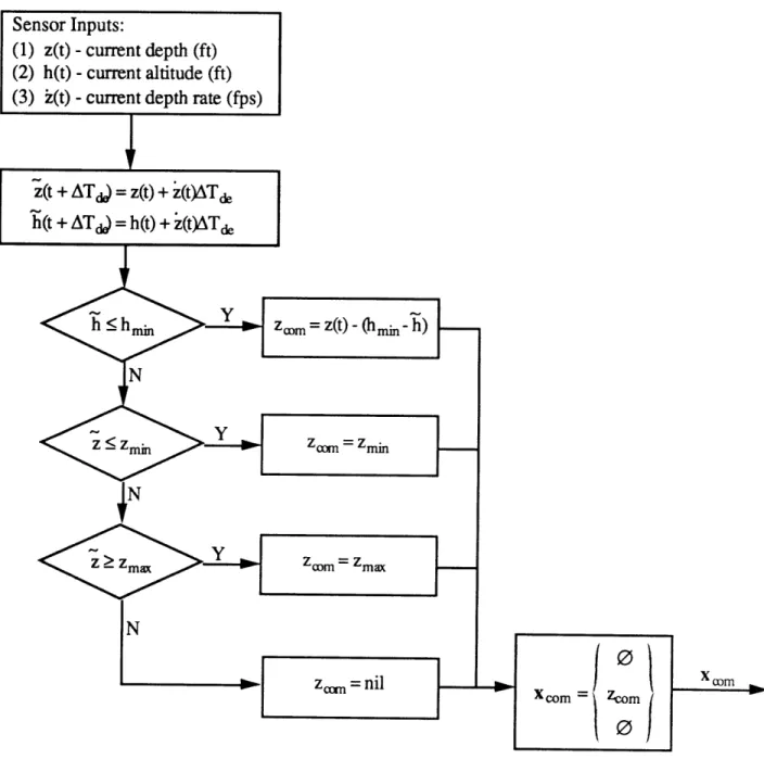
The design of the depth envelope module consists of three major elements: sensor processing, activation, and control command generation.
Sensor Processing
The sensor input to the depth envelope module consists of: the current sensed altitude h(t), the current sensed depth z(t), and the current sensed depth rate z(t). In addition to sensor inputs, the depth envelope module has four planner parameter inputs.
These are the minimum altitude hmin, the minimum depth Zmin, the maximum depth zmax, and the depth envelope update time interval ATe. The planner parameters are specified prior to the mission based on the mission requirements, although it would be possible for a higher mission planning module to set these values during mission execution. The determination of the update time interval is dependent on the implementation of the modules
on the microprocessor and will be discussed in Chapter 5.
The depth and altitude are projected based on the current depth rate to obtain an estimate of the depth and altitude at the next time the depth envelope module is scheduled to run. The estimates of depth and altitude are based on projections of the depth and altitude state over a time period which corresponds to the time interval between depth envelope module updates. Making the assumption that the depth rate remains constant over the update time interval and that the depth of the sea floor remians roughly constant over the interval::
2(t + ATd) = estimated depth at next update = z(t) + i(t)ATd
h(t + ATe) -= estimated altitude at next update = h(t) -i(t)ATd, where:
z(t) : current sensed depth from depth transducer h(t) : current sensed altitude from altitude sonar
i(t) : current sensed depth rate
AT& : depth envelope update time interval in seconds
Activation
The depth envelope module is activated when one or more of the three depth envelope parameters are violated by the estimated depth or estimated altitude. Activation is triggered by any of the following three conditions: