Design and Architecture of the
Context Interchange System
by
Syed Ahmed Zaman Shah
Submitted to the Department of Electrical Engineering and Computer Science
in Partial Fulfillment of the Requirement of the Degree of
Master of Engineering in Electrical Engineering and Computer Science
at the Massachusetts Institute of Technology
May 1998
© 1998 M.I.T. All rights reserved.
The author hereby grants to M.I.T. permission to reproduce and distribute, publicly, paper and electronic copies of this thesis
and to grant others the right to do so.
Author
Department of Electrical Engineering and Computer Science
1 May 01, 1998
Certified by
Professor Stuart Madnick -Thesis Supervisor
Accepted
by-Smith
A-
Ai tur C.
Chairman, Department Committee on Graduate Theses
Design and Architecture of the
Context Interchange System
by
Syed Ahmed Zaman Shah
Submitted to the
Department of Electrical Engineering and Computer Science
May 18, 1998
In Partial Fulfillment of the Requirement of the Degree of Master of Engineering in Electrical Engineering and Computer Science
ABSTRACT
The Context Interchange Project (COIN) presents a unique approach to the problem of semantic conflict resolution among multiple heterogeneous data sources. The system presents a uniform view to the user for all the available data sources. The semantic conflicts are automatically detected and reconciled by the system. In this thesis, I describe the COIN system from a both as a user's perspective and an application developer's perspective. Then I discuss the current architecture of the system from the software-engineering point of view and propose modifications to the system that will make the system more modular and easy for the system developers to maintain and enhance the system.
Thesis Supervisor: Professor Stuart Madnick
Acknowledgments
I would like to thank many people for their support and guidance throughout my graduate work. First, I would like to thank Professor Stuart Madnick and Dr. Michael Siegel, for their guidance and support, both academic and personal, throughout the last one year. My most sincere thanks to Ste'phane Bressan for his immeasurable help with my work. I cannot thank him enough for putting up with me and my ignorance while all that time keeping me on track and helping me whenever I needed guidance. I would also like to thank my fellow COINers, Allen Moulten, Thom Lee, Ricardo Ambrose and many others who made it a very fun and interesting place to work and learn. My deepest thanks to my family, particularly my mother and my younger brother, Yassir Shah(whose guidance and love are the primary reasons for my academic success), for their support, confidence, and love. Thanks to my friends, particularly, Omar Raza Khan and Srikar Srinath for putting up with me when I needed somebody to talk to. Most of all, I would like to thank Allah for all the opportunities and successes that He granted me over the years.
Table of Contents
1. INTRODUCTION ... 8
2. OVERVIEW ... 15
2.1 THE COIN FRAM EW ORK... 15
2.1.1 Context Mediator ... ... 16
2.1.2 System Perspective ... ... ... 16
2.1.3 Application D om ains... 17
2.2 TOP LEVEL ARCHITECTURE ... 18
2.2.1 Client Processes ... 19
2.2.2 Server Processes... .. ... ... .... 19
2.2.3 M ediator Processes ... ... ... 20
3. COIN ARCHITECTURE ... 21
3.1 A MOTIVATIONAL EXAMPLE ... ... 21
3.2 DOMAIN MODEL AND CONTEXT DEFINITION ... 24
3.3 ELEVATION A XIOM S... 26
3.4 M EDIATION SYSTEM ... .... . ... 28
3.4.1 SQL to Datalog Query Compiler... 29
3.4.2 M ediation Engine... 30
3.4.3 Query Planner and optimizer... 33
3.4.4 Runtime engine...37
3.5 W EB W RAPPER ... 37
3.5.1 Web wrapper architecture ... ... 39
3.5.2 Wrapping a web site ... ... ... ... 40
4. BUILDING AN APPLICATION ... ... 42
4.1 PRE-APPLICATION SETUP ... .... 43
4.2 DOMAIN M ODEL DEFINITION... 44
4.3 IDENTIFICATION OF THE SOURCES AND RELATIONS ... 45
4.4 SOURCE AND RELATION DEFINITION . ... 47
4.4.1 Inserting the Data Sources ... ... 47
4.4.2 Inserting the Relations... ... 48
4.5 ELEVATION OF THE DATA SOURCES ... 51
4.5.1 Mapping the Physical Types to Semantic Types... 52
4.5.2 Creating the Semantic Relations... 53
4.5.3 Creating Views to Ease Application Development ... 55
4.6 ADDITION OF INTEGRITY CONSTRAINTS ... ... 57
4.7 CONTEXT DEFINITION FOR EACH DATA SOURCE... 58
4.7.1 Recognizing the Semantic Differences ... ... 58
4.7.2 Creating the Contexts... 60
4.8 ADDITION OF THE CONVERSION FUNCTIONS ... ... 61
5. COIN SYSTEM: PRESENT AND FUTURE ... ... 66
5.1 THE CURRENT SYSTEM... ... ... 66
5.2 ANALYSIS OF THE DESIGN ... ... ... 67
5.2.1 How simple is too simple? ... ... 67
5.2.2 Tight Integration at the cost of flexibility... ... 68
5.2.3 Modularity-Enough Said ... ... 69
5.3 SUGGESTED DESIGN MODIFICATIONS ... ... 70
5.3.1 More Flexible Interface to the COIN Server ... 70
5.3.2 Formalizing the Interfaces ... ... 72
5.4 THE NEW ARCHITECTURE ... ... ... 74
5.5 THE N EXT STEP... ... 75
6. CONCLUSIONS ... 76
REFERENCES ... 77
APPENDIX A: DOMAIN MODEL ... ... 80
APPENDIX B: DATA SOURCE DESCRIPTIONS...81
APPENDIX C: ELEVATION AXIOMS ... 85
APPENDIX D: INTEGRITY CONSTRAINTS ... 94
APPENDIX E: CONTEXT DEFINITIONS ... ... 97
Chapter 1
1. Introduction
The only thing more important than a well-designed software system is a well-written set of documentation for that system. Any system that does anything useful has to be accompanied by documentation. The most common form of documentation is a user manual explaining the features of the systems for the users of that system and how to use those features. For a very small system e.g. is command on a UNIX system, that might just be one page listing all the command line flags for that command and a brief explanation of what each flag does. But for large systems e.g. operating systems or database management systems, the documentation might contain many volumes. The Oracle DBMS V7 [19] comes with a documentation set that contains 32 volumes each about 500-700 pages in length. Large software companies spend a significant amount of time and resources trying to produce a coherent set of documentation for the users.
Large software systems usually offer a very rich set of features. This large feature set however comes at the cost of complexity. Therefore in order for the users of these systems to be able to make use of all those features, good documentation plays an important part. No matter how many features a system offers, if they are not well documented and hence cannot be made use of, then they might as well not exist. A good set of documentation goes farther than that. It even saves time and money for the system developers since rather than them having to explain how to use the system to the users over and over again, the system designers and developers can expend one-time effort producing a comprehensive set of documentation once. Once a good set of documents is produced, the users can then simply learn about the features of the system by reading the manuals and figure out how to use the systems. Meanwhile, the system designers can spend their precious time designing the next great version of the system.
The documentation mentioned above is usually referred to as user documentation as it is directed towards the end users of the system. There is another type of documentation whose target audience are not the users of the system, but the developers of the system. This type of documentation is usually called system documentation. While the user documentation is primarily concerned about how to use the system, the system documentation in essence captures the knowledge about the system itself. These documents contain information about how the system was designed. These usually include the overall architecture of the system, design and in some cases implementation of each syestem (e.g. the algorithms used etc.). In addition to that, the interfaces of each system are explained, which essentially provides the information about how each sub-system interacts with other sub-sub-systems and how they all fit together to form a complete system.
There is yet another type of documentation that often accompanies large database systems and Information Systems. This set of documentation is directed at System Administrators. This documentation deals with the issues of how to install and configure the system based on the need of each site and how to manage and administer the system. An example might be a database management system. In this case, the documentation would discuss various configurations of systems based on the number of users that are going to use the system and how big the database is expected to grow. The documentation would list how to install the various sub-systems, how to configure each one those sub-system, how to create initial database, issues on how to bring up or shutdown a database. The documentation would also talk about how to create and maintain user accounts, permissions on who can access what part of the database and such. This set of documentation quite important in the above-mentioned systems and is normally called System Administration Guide.
For most systems however, user document and the design document are still the most important categories of documentation. While the user documentation is important, almost necessary for the users to be able to use the system, design documentation is equally
important for a number of reasons. The first and most important use of design document is that it serves as a roadmap for the system designers as to where the systems stand and where it is heading. Since the design document captures the knowledge about the system, the designers, while talking about the future versions of the system, know exactly what features the system currently offers and what are the features that should be added to the system. In addition to that, as the systems grow large, it becomes almost impossible for a single person to know all the features and their design intimately. The design document
serves as a central place where the architecture of the whole system is captured, thus making it easy for the designers to analyze how the various design decisions for new features would integrate into the existing system. This allows the system designers to make the design choice for the new features that would best fit with the current architecture of the system.
While the system designers work on the design of the system, system developers are the ones who actually work on the implementation of the system. If the system designers do a good job of writing the design document and system specifications, system developers can then just take the system design and use the specification to go ahead and actually implement the features designed by the system. Of course the system developers will be talking to the system designers in a constant feedback cycle, since the developers while developing the system might come across cases that the system designers either overlooked or forgot to account for which would require revisions of the system design specifications. But if the design documents were poorly written, this would cause a much higher communication overhead, as the system developers would be needlessly asking the system designers for explanations. The more important benefit of the design document is that it allows for modular development. If each subsystem is adequately defined and specified, then the developer who is implementing that particular subsystem need not worry about any other part of the system. As long as she implements her subsystem according to the specified specification, the various subsystems can be developed in parallel and in the end be integrated into the main system with relative ease.
Over the lifetime of large software systems, a great number of developers and designers work on the design and development of the system. Usually with the passage of time, the original system designers move on to do other projects or work on other systems. New people come on board and carry on the work of people who left. As the original designers leave, rather than walking out of the door with all the knowledge of the system, they need to transfer the knowledge of the system that they possess to the new designers that are taking their place. This can be achieved in two ways. The previous designers can hold training sessions where they can transfer the knowledge to the new designers in person by having one-on-one meeting. This method is cumbersome, requires a lot of co-ordination
(which is not always possible as the end dates of the leaving designers and the starting dates of the new designers do not always coincide) and can be flawed as the old designers might forget some crucial details of the system design. Now instead of having to train the people who are replacing them by doing a manual brain dump, if the departing designers have been maintaining a good design document, they do not any of the above-mentioned issues to deal with. The retiring designers can leave anytime at their convenience. The new people can then simply pick up the design documentation and come up to speed after
reading the documents and become productive very quickly.
During the latter phases of the software lifecycle, the number of new features that are being added to the system goes down and the system slowly goes into maintenance mode. During that time, very few people are working on the system design and system maintainers who simply fix bugs and field customer request do most of the work. A good and well-maintained set of design document becomes very crucial during that phase the software life. As most of the original people who actually developed the system have left by then, the system maintainers who do not normally have intimate knowledge of the workings of the systems have just the design documents to go by. Thus good documents save the maintainers a lot of time and the project administrators a lot of money.
To summarize, documentation is a crucial part of the software systems and its importance cannot be underestimated. There are two types of documentation, user documentation and
design documentation. User documentation usually explains how to install and use the system, hence it concentrates on the features of the systems and how those features can be used. The design documentation, on the other hand, is targeted towards the designers and the developers of the system itself. The design document contains the information about the overall architecture of the system, design and possibly implementation of each subsystem and how each subsystem interacts with the rest of the subsystems to form the complete system. Both sets of documentation are necessary and crucial for the large software systems.
In the recent past, a lot of research has been done by various researches on the Context Interchange System. Over the last few years, the system has undergone major revision overhaul and a lot of features have been added to the system. In most cases, as individual researchers were working on certain parts of the system, they carried on their work in those subsystems that they were interested in and mostly ignored the rest of the system. They did not give a lot of thought as to how their newly modified subsystem or in some cases, entirely new subsystem would integrate with the rest of the system. Another factor that contributed to the "chaos" was that the Context Interchange group by its nature has a very dynamic environment. Every year students graduate and leave and new students take their place. The graduating students barely spend any time worrying about above-mentioned issues like how the subsystem that they worked on would integrate with the rest of the system. In most cases they work on their subsystem in isolation, get it to work, make some effort to integrate into the rest of the system. If it works, wonderful, if not, well, they leave anyway. It would however be unfair to put all the blame on all these researchers. They are constrained for time and also by the fact that a good set of design documentation that can guide them does not exist. Researchers who are working on some specific pieces of the system either write papers or a thesis and thus preserve that knowledge. However, there have not been a concerted effort by some person to take all that is out there, and come up with a set of documentation for the system.
That is the hole this thesis plugs. In this thesis, I will be providing a set of coherent documentation for the Context Interchange System (COIN). The documentation is broadly divided into two sets of documents. Each set of documentation is directed at a certain task. The two sets are:
* Application Development Tutorial: This document is written to teach the users of the system on how to write applications on top of COIN system for the end users. This document is in the form of a tutorial. We start with an idea of an application and then guide the user step by step on how to build that application.
* System design and architecture document: This document in some sense is the main document as it captures the design and architecture of the whole system. While primarily targeted at designers, who want to know the design and architectures of the COIN system, this document has enough depth that it also serves the purpose of an overall design document.
In addition to the above, the thesis also contains a discussion of the current design of the COIN system. It talks about the various tradeoffs and then based on the current design, proposes modifications to the current design that will improve the modularity of the system and make it ready for the distributed development that we are heading. I will discuss all the advantages and tradeoffs of the proposed modifications as compared to the existing design in an effort to prove that it is indeed beneficial for us to move towards the new design changes.
The rest of the thesis is as follows. Next chapter contains a high level architecture of the system. Chapter 3 discuses each sub component in somewhat using an example scenario. Chapter 4 consists of application development tutorial with the example. Chapter 5 is slightly different in tone from the rest of the chapters in that while the other chapters are primarily system documentation, this chapter departs from the theme and instead critiques the current design of the COIN system from the software-engineering point of view. This chapter talks about some of the shortcoming of the existing system and then proposes
some not too radical modifications to the design that will address those shortcomings. Chapter 6 concludes the thesis. Appendices contain all the source code that is used in building the example application discussed in this thesis.
Chapter 2
2. Overview
The COintext INterchange (COIN) strategy seeks to address the problem of semantic
interoperability by consolidating distributed data sources and providing a unified view
over them. COIN technology presents all data sources as SQL databases by providing generic wrappers for them. The underlying integration strategy, called the coin model, defines a novel approach for mediated [9] data access in which semantic conflicts among heterogeneous systems are automatically detected and reconciled by the Context
Mediator. Thus the COIN approach integrates disparate data sources by providing semantic interoperability (the ability to exchange data meaningfully) among them.
2.1 The COIN Framework
The COIN framework is composed of both a data model and a logical language, COINL [ 11], derived from the family of F-Logic [10]. The data model and language are used to define the domain model of the receiver and data source and the context [12] associated with them. The data model contains the definitions for the "types" of information units (called semantic types) that constitute a common vocabulary for capturing the semantics of data in disparate systems. Contexts, associated with both information sources and receivers, are collections of statements defining how data should be interpreted and how potential conflicts (differences in the interpretation) should be resolved. Concepts such as
semantic-objects, attributes, modifiers, and conversion functions defmine the semantics of
data inside and across contexts. Together with the deductive and object-oriented features inherited from F-Logic, the COIN data model and COINL constitute an appropriate and expressive framework for representing semantic knowledge and reasoning about semantic heterogeneity.
2.1.1 Context Mediator
The Context Mediator is the heart of the COIN project. It is the unit that provides mediation for user queries. Mediation is the process of rewriting queries posed in the receiver's context into a set of mediated queries where all potential conflicts are explicitly solved. This process is based on an abduction [13] procedure which determines what information is needed to answer the query and how conflicts should be resolved by using the axioms in the different contexts involved. Answers generated by the mediation unit can be both extensional and intentional. Extensional answers correspond to the actual data retrieved from the various sources involved. Intentional answers, on the other hand, provide only a characterization of the extensional answer without actually retrieving data from the data sources. In addition, the mediation process supports queries on the semantics of data that are implicit in the different systems. There are referred to as
knowledge-level queries as opposed to data-level queries that are enquires on the factual
data present in the data sources. Finally, integrity knowledge on one source or across sources can be naturally involved in the mediation process to improve the quality and information content of the mediated queries and ultimately aid in the optimization of the
data access.
2.1.2 System Perspective
From the systems perspective, the COIN strategy combines the best features of the
loose-and tight-coupling approaches to semantic interoperability [14] among autonomous loose-and
heterogeneous systems. Its modular design and implementation funnels the complexity of the system into manageable chunks, enables sources and receivers to remain loosely-coupled to one another, and sustains an infrastructure for data integration.
This modularity, both in the components and the protocol, also keeps our infrastructure scalable, extensible, and accessible [2]. By scalability, we mean that the complexity of creating and administering the mediation services does not increase exponentially with the number of participating sources and receivers. Extensibility refers to the ability to incorporate changes into the system in a graceful manner; in particular, local changes do
not have adverse effects on other parts of the system. Finally, accessibility refers to how a user in terms of its ease-of-use perceives the system and flexibility in supporting a variety of queries.
2.1.3 Application Domains
The COIN technology can be applied to a variety of scenarios where information needs to be shared amongst heterogeneous sources and receivers. The need for this novel technology in the integration of disparate data sources can be readily seen in the following examples.
One very obvious and useful application of the COIN technology is in the context of financial domain. This technology can be successfully used to assist financial analysts in conducting research and valuing and comparing companies in this global economy where companies follow different business practices and accounting principals depending on the country they operate in. When the financial analysts analyze different companies that might not be based in the same countries, and compare those companies, they rely on the financial data provided by various information providers. There are a number of information providers that provide historical data and other research both to institutions (investment banks, brokerages) as well as individual investors. Most of the time this information is presented in different formats and must be interpreted with different rules. Some examples are scale-factors and currency of monetary figures. Mismatches among these assumptions across sources of inside one source can be critical in the process of financial decision making.
In the domain of manufacturing inventory control, the ability to access design, engineering, manufacturing and inventory data pertaining to all parts, components, and assemblies are vital to any large manufacturing process. Typically, thousands of contractors play roles and each contractor tends to set up its data in its own individualistic manner. Managers may need to reconcile inputs received from various contractors, compare various tenders submitted by different contractors for a specific order in order to
determine the best bid among all the bids made in order to optimize inventory levels and ensure overall productivity and effectiveness. COIN technology can play an important role in standardizing various formats the contractors put their bid in thus facilitating the job of the managers while choosing the best bid.
Finally, the modern health care enterprise lies at the nexus of several different industries and institutions. Within a single hospital, different departments (e.g. internal medicine, medical records, pharmacy, admitting, and billing) maintain separate information systems yet must share data in order to ensure high levels of care. Medical centers and local clinics not only collaborate with one another but also with state and federal regulators, insurance companies, and other payer institutions. This sharing requires reconciling differences such as those of procedure codes, medical supplies, classification schemes, and patient records.
2.2 Top Level Architecture
MEDIATOR PROCESSES
Data Store for Intermediate Results
Figure 1: COIN System Overview
ODBC-compliant Apps
(e.g Microsoft Excel)
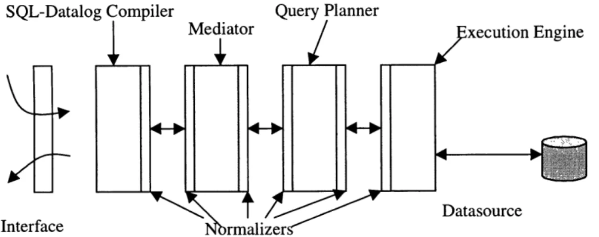
The feasibility and features of the proposed strategy of using context mediation to solve semantic differences between various heterogeneous data sources has been concretely demonstrated in a working system that provides mediated access to both on-line structured databases and semi-structured data sources such as web sites. This demonstration system implements most of the important concepts of context interchange strategy and is called the COIN System. This section introduces the COIN System and gives a very high level architectural view of the system. The infrastructure leverages on the World Wide Web in a number of ways. First, we rely on the hypertext transfer protocol for the physical connectivity among sources and receivers and the different mediation components and services. Second, we employ the hypertext markup Language and Java for the development of portable user interfaces. Figure 1 shows the architecture of the COIN system. It consists of three distinct groups of processes.
2.2.1 Client Processes
The client processes provide the interaction with receivers and route all database requests to the Context Mediator. An example of a client process is the multi-database browser [15], which provides a point-and-click interface for formulating queries to multiple sources and for displaying the answers obtained. Specifically, any application program that posts queries to one or more sources can be considered a client process. This can include all the programs (e.g. spread sheet software programs like Excel) that can communicate using the ODBC bridge to send SQL queries and receive results. It does not matter to the backend system where the requests are coming from or how as long as they are well-formatted SQL queries.
2.2.2 Server Processes
Server processes refer to database gateways and wrappers. Database gateways provide physical connectivity to database on a network. The goal is to insulate the Mediator Process from the idiosyncrasies of different database management systems by providing a uniform protocol for database access as well as canonical query language (and data model)
for formulating the queries. Wrappers, on the other hand, provide richer functionality by allowing semi-structured documents on the World Wide Web to be queried as if they were relational databases. This is accomplished by defining an export schema for each of these web sites and describing how attribute-values can be extracted from a web site using pattern matching [16].
2.2.3 Mediator Processes
The Mediator processes refer to the system components that collectively provide the mediation services. These include SQL-to-datalog compiler, context mediator, and query planner/optimizer and multi-database executioner. SQL-to-Datalog compiler translates a SQL query into its corresponding datalog format. Context mediator rewrites the user-provided query into a mediated query with all the conflicts resolved. The planner/optimizer produces a query evaluation plan based on the mediated query. The multi-database executioner executes the query plan generated by the planner. It dispatches subqueries to the server processes, collates the intermediary results, and returns the final answer to the client processes.
Of these three distinct groups of processes, the most relevant to our discussion is the group of mediator processes that run the mediation system as those are the processes that comprise the COIN backend system. In the next chapter, we discuss the mediation process and all the sub components that make up the mediation process. We first start by a scenario of a stock analyst who needs to gather information from a collection of sources each having different assumptions about the data. We will explain how mediation can make the analyst's job much easier. After that, we expand on that example and first explain the notion of a domain model and then move on to talk about each subsystem in detail.
Chapter 3
3. COIN Architecture
3.1 A motivational example
Worldscope Datastream Figure 2In this section, we use an example of a financial analyst doing research on Daimler Benz. She needs to find out the net income, net sales, and total assets of Daimler Benz Corporation for the year ending 1993. In addition to that, she needs to know the closing stock price of Daimler Benz. She normally uses the financial data stored in the database
Worldscope, but for this assignment, Worldscope does not have all the information that
she needs. She recalls Jill, her technophile coworker telling her about two new databases,
Datastream and Disclosure and how they contained all the information that Jill needed.
So she sets off to get the information that she needs. She starts off with the Worldscope database. She knows that Worldscope has total assets for all the companies. She logs into the Oracle, which contains the Worldscope data and issues a query:
select company_name, total_asets from worldscope where company_name = "'DAIMLER-BEZG AG'';
She immediately gets back the result:
DAIMLER-BENZ AG 5659478
Satisfied, she moves on. After looking at the data information for the new databases, she figures out that she can get the data on net income from Disclosure and net sales from
Datastream. For net sales, she issues the query:
select company_name, net_income from disclosure
where company_name = ' DAIMLER-BENZ AG'';
The query does not return any records. Puzzled, she checks for typos and tries again. She knows that the information exists. She tries one more time this time entering partial name for DAIMLER BENZ.
select company_name, net_income from disclosure where company_name like "'DAIMLER%'';
She gets the record back:
DAIMLER BENZ CORP 615000000
She now realizes that the data sources do not conform to the same standards, as it becomes obvious from the fact that the two data sources store the name of the same company differently. Cautious, she presses on and issues the third query:
select name, total_sales from datastream where name like "'DAIMLER%'';
She gets the result:
DAIMLER-BENZ 9773092
As she is putting the results together, she realizes that there a number of things unusual about this data set. First of all, the total sales are twice as much as the total assets of the company, which is highly unlikely for a company like Daimler Benz. What is even more
disturbing is that net income is almost ten times as much as net income. She immediately realizes something is wrong and grudgingly opens up the fact sheet that came with the databases. Upon studying them, she finds out some interesting facts about the data that she was using so gaily. She finds out that Datastream has a scale factor of 1000 for all the financial amounts, while Disclosure uses a scale factor of one. In addition, both
Disclosure and Datastream use the country of incorporation for the currency. She knew
that Worldscope used a scale factor of 1000 but at least everything was in U.S Dollars. Now she has to reconcile all the information by finding a data source (possibly on the web) that contains the historical currency exchange rates. In addition to that, she still has to somehow find another data source and get the latest stock price for Daimler Benz. For that, she knows she will first have to find out the ticker symbol for Daimler Benz and then look it up using one of the many stock quote servers on the web.
Enter context mediation. The context mediation system automatically detects and resolves all the semantic conflicts between all the data sources being used and presents the results to the user in the format that the user is familiar with. In the above example, if the analyst was using context mediation system instead, all she had to do was formulate and ask only one query without having to worry about the underlying differences between the data after stating that she wanted the results back in the Worldscope context:
select worldscope.total_assets, datastream.total_sales, disclosure.net_income, quotes.Last
from worldscope, datastream, disclosure, quotes where worldscope.company_name = "DAIMLER-BENZ AG" and
datastream.as of date = "01/05/94" and
worldscope.company_name = datastreama.name and
worldscope.company_name = disclosure.company_name and worldscope.company_name = quotes.cname ;
The system would then have detected all the conflicts that the analyst had to deal with when she was not using the context mediation system, and would have resolved those conflicts without the analyst's explicit intervention.
In the next few sections, we will use the above scenario to discuss the concept of a
domain model and how a domain model is defined and created. We will also explain the
various subsystems and how they work.
3.2 Domain Model and Context definition
The first thing that we need to do before we can start using context mediation to have concept and definition of the domain model in the application domain that we are working in. A domain model specifies the semantics of the "types" of information units, which constitutes a common vocabulary used in capturing the semantics of data in disparate sources. In other words it defines the ontology which will be used. The various semantic types, the type hierarchy, and the type signatures (for attributes and modifiers) are all defined in the domain model. Types in the generalized hierarchy are rooted to system types, i.e. types native to the underlying system such as integers, strings, real numbers etc.
number c hn stg
-T. Cop
country-Currency- officia1Curren Name
T y p e
--- ---.
..
'/-
-- --
,
_
- - - - - - - - - -Name
company
- -. Inheritance
Figure 3:Financial Domain Model
--- Attribute ModifierFigure 3 is lists the domain model that is used in our example. In the domain model described, there are three kinds of relationships expressed.
Inheritance: This is the classic type inheritance relationship. All semantic types inherit from basic system types. In the domain model, type companyFinancials inherits from basic type string.
Attributes: In COIN [17], objects have two forms of properties, those which are structural properties of the underlying data source and those that encapsulate the underlying assumptions about a particular piece of data. Attributes access structural properties of the semantic object in question. For instance, the semantic type companyfinancials has two attributes, company and fyEnding. Intuitively, these attributes define a relationship between objects of the corresponding semantic types. Here, the relationship formed by the company attribute states that for any company financial in question, there must be corresponding company to which that company financial belongs. Similarly, the fyEnding attribute states that every company financial object has a date when it was recorded.
Modifiers: These define a relationship between semantic objects of the corresponding
semantic types. The difference though is that the values of the semantic objects defined by the modifiers have varying interpretations depending on the context. Looking once again at the domain model, the semantic type companyFinancials defines two modifiers, scaleFactor and currency. The value of the object returned by the modifier scaleFactor depends on a given context.
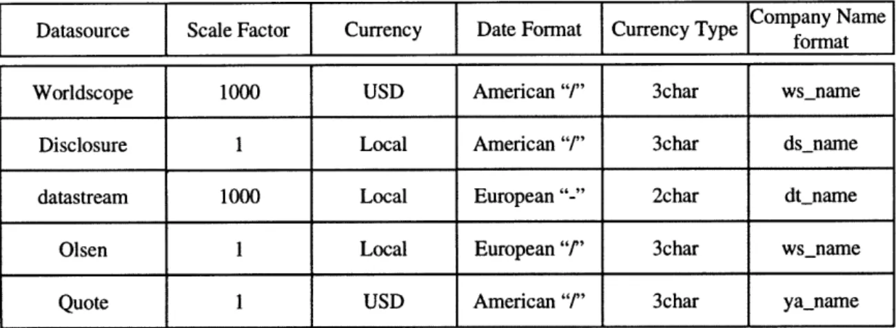
Once we have defined the domain model, we need to define the contexts for all the sources. In our case, we have three explicit data sources with the assumptions about their data in Figure 4. A simplified view of how part of a context is included. A complete discussion of what each of these statements mean is in Chapter 4.
modifier(companyFinancials, 0, scaleFactor, cws,
M):-cste(basic, M, cws, 1000).
modifier(companyFinancials, 0, currency, c_ws, M):-cste(currencyType, M, c_ws, "USD").
modifier(date, 0, dateFmt, c_ws,
One last thing that needs to be provided as part of a context is the set of conversion functions between different contexts. An example is the conversion between scale factors in different contexts. Following is the conversion routine that is used when scale factors are not equal:
cvt(companyFinancials, _0, scaleFactor, Ctxt,
Mvs, Vs, Mvt, Vt)
:-Ratio is Mvs / Mvt,
Vt is Vs * Ratio.
Context Table
Datasource Scale Factor Currency Date Format
Figure 4
3.3 Elevation Axioms
The mapping of data and data-relationships from the sources to the domain model is accomplished via the elevation axioms. There are three distinct operations that define the elevation axioms:
* Define a virtual semantic relation corresponding to each extensional relation. * Assign to each semantic object defined its value in the context of the source.
* Map the semantic objects in the semantic relation to semantic types defined in the domain model and make explicit any implicit links (attribute initialization) represented by the semantic relation.
We will use the example of the relation Worldscope to show how the relation is elevated. The Worldscope relation is a table in oracle database and has the following columns:
Name Type
COMPANY_NAME VARCHAR2(80)
LATEST ANNUAL FINANCIAL DATE VARCHAR2(10) CURRENT_OUTSTANDING_SHARES NUMBER
NET INCOME NUMBER
SALES NUMBER
COUNTRY_OF_INCORP VARCHAR2(40)
TOTAL ASSETS NUMBER
And here is part of how the elevated relation looks like:
'WorldcAF_p' (
skolem(companyName, Name, c_ws, 1, 'WorldcAF' (
FYEnd, Shares, Income, Sales, Assets, Incorp)),
skolem(date, FYEnd, c_ws, 2, 'WorldcAF' ( Name,
Shares, Income, Sales, Assets, Incorp)),
skolem(basic, Shares, c_ws, 3, 'WorldcAF' ( Nam
Shares, Income, Sales, Assets, Incorp)),
skolem(companyFinancials, Income, c_ws, 4, 'Wo Name, FYEnd, Shares, Income, Sales, Assets, Incorp)
skolem(companyFinancials, Sales, c_ws, 5, 'Wor Name, FYEnd, Shares, Income, Sales, Assets, Incorp)
skolem(companyFinancials, Assets, c_ws, 6, 'Wo
Name, FYEnd, e, FYEnd, rldcAF'(
),
ldcAF '( ),dcF rldcAF'(Name, FYEnd, Shares, Income, Sales, Assets, Incorp)),
skolem(countryName, Incorp, c_ws, 7, 'WorldcAF' ( Name,
FYEnd, Shares, Income, Sales, Assets, Incorp))
) :- 'WorldcAF'(Name, FYEnd, Shares, Income, Sales,
We first define a semantic relation for Worldscope. A semantic relation is then defined on the semantic objects in the corresponding relation attributes. The data elements derived from the extensional relation are mapped to semantic objects. These semantic objects define a unique object-id for each data element. In the example above each skolem term defines a unique semantic object corresponding to each attribute of the extensional relation. In addition to mapping each physical relation to a corresponding semantic object, we also define and initialize other relations defined in the domain model. The relations that come under this category are attribute and modifiers.
3.4 Mediation System
In the following sections, we will describe each mediation subsystem in somewhat more detail. We will use the application scenario we used earlier about the financial analyst trying to gather information about Daimler Benz Corp. We will start with the query, and then we will describe the application as it is programmed, explaining domain and how the context information for various sources is specified. Then we will follow the query as it passes through each subsystem.
We know the query that we are going to ask the system is:
selet worldscope.total_assets, datastream.total_sales,
disclosure.net_income, quotes. Last
from worldscope, datastream, disclosure, quotes where
worldscope .company_name = "DAIMLER-BENZ AG" and
datastream.as of date = "01/05/94" and
worldscope.company_name = datastreama.name and
worldscope.company_name = disclosure.company_name and worldscope. company_name = quotes.cname ;
We will be asking the query in the Worldscope context. What this means is that once the mediation system has processed all parts of the query, the system then converts the result into the Worldscope context and returns the converted results back to the user.
3.4.1 SQL to Datalog Query Compiler
The SQL query as it is passed in to the system, is fed to the SQL query compiler. The query compiler takes in the SQL query and first parses the SQL into its corresponding datalog form while at the same time using the elevation axioms it elevates the data sources into its corresponding elevated data objects. The corresponding datalog query for the SQL query above is:
answer(total_assets, total_sales, net_income, last) WorldcAF_p(V27, V26, V25, V24, V23, V22, V21), DiscAF_p(V20, V19, V18, V17, V16, V15, V14), DStreamAF_p(V13, V12, V11, V10, V9, V8), quotes_p(V7, q_last) , Value(V27, c_ws, V5) , V5 = "DAIMLER-BENZ AG", Value(V13, c_ws, V4) , V4 = "01/05/94", Value(V12, c_ws, V3) , V5 = V3, Value(V20, c_ws, V2) , V5 = V2, Value(V7, c ws, V1), V5 = V1, Value(V22, c_ws, total_assets), Value(V17, c_ws, total_sales) ,
Value(V11, c_ws, net income), Value(qlast, c_ws, last) .
As can be seen, the query now contains elevated data sources along with a set of predicates that map each attribute to its value in the corresponding context. Since the user asked the query in the Worldscope context (denoted by c_ws), the last four predicates in the translated query ascertain that the actual values returned as the solution of the query need to be in the Worldscope context. The resulting unmediated datalog query is then fed to the mediation engine.
3.4.2 Mediation Engine
The mediation engine in some respects is the heart of the system. This is the part of the system that detects and resolves possible semantic conflicts. In essence, the mediation is a query rewriting process. The actual mechanism of mediation is based on an abduction engine [13]. The engine takes a datalog query and a set of domain model axioms and computes a set of abducted queries such that the abducted queries have all the differences resolved. The system does that by incrementally testing for potential semantic conflicts and introducing conversion functions for the resolution of those conflicts. The mediation engine as its output produces a set of queries that take into account all the possible cases given the various conflicts. Using the same example from above, if the mediation engine were fed the datalog query output by the SQL compiler, along with the domain model and contexts stated above, we would get the following set of abducted queries:
answer(V108, V107, V106, V105)
:-datexform(V104, "European Style -", "01/05/94",
"American Style /"),
Name map_Dt_Ws (V103, "DAIMLER-BENZ AG"),
Name map_Ds_Ws(V102, "DAIMLER-BENZ AG"),
Ticker_Lookup2 ("DAIMLER-BENZ AG", V101, V100), WorldcAF("DAIMLER-BENZ AG", V99, V98, V97, V96, V108, V95), DiscAF(V102, V94, V93, V92, V91, V90, V89), V107 is V92 * 0.001, Currencytypes (V89, USD) , DStreamAF(V104, V103, V106, V88, V87, V86), Currency_map (USD, V86) , quotes(V101, V105). answer(V85, V84, V83, V82)
datexform(V81, "European Style -", "01/05/94",
"American Style /"),
Name_map_Ds_Ws(V79, "DAIMLER-BENZ AG"), Ticker_Lookup2("DAIMLER-BENZ AG", V78, V77), WorldcAF("DAIMLER-BENZ AG", V76, V75, V74, V73, V85, V72), DiscAF(V79, V71, V70, V69, V68, V67, V66), V84 is V69 * 0.001, Currencytypes(V66, USD), DStreamAF(V81, V80, V65, V64, V63, V62), Currency_map(V61, V62), <>(V61, USD),
datexform(V60, "European Style /", "01/05/94",
"American Style /"),
olsen(V61, USD, V59, V60),
V83 is V65 * V59,
quotes(V78, V82) .
answer(V58, V57, V56, V55)
:-datexform(V54, "European Style -", "0
"American Style /"),
Name map_Dt_Ws(V53, "DAIMLER-BENZ AG" Name_map_Ds_Ws(V52, "DAIMLER-BENZ AG" Ticker_Lookup2("DAIMLER-BENZ AG", V51 WorldcAF("DAIMLER-BENZ AG", V49, V48, 1/05/94",
),
),
V50), V47, V46 V45), DiscAF(V52, V44, V43, V42, V41, V40, V39), V38 is V42 * 0.001, Currencytypes(V39, V37), <>(V37, USD),datexform(V36, "European Style /", V44, "American Style /"), olsen(V37, USD, V35, V36), V57 is V38 * V35, DStreamAF(V54, V53, V56, V34, V33, V32), Currencymap (USD, V32), , V58,
quotes(V51, V55) .
answer(V31, V30, V29, V28)
:-datexform(V27, "European Style -", "01/05/94",
"American Style /"),
Name_map_Dt_Ws(V26, "DAIMLER-BENZ AG"), Name_map_Ds_Ws(V25, "DAIMLER-BENZ AG"),
Ticker_Lookup2("DAIMLER-BENZ AG", V24, V23), WorldcAF("DAIMLER-BENZ AG", V22, V21, V20, V19, V31, V18), DiscAF(V25, V17, V16, V15, V14, V13, V12), V11 is V15 * 0.001, Currencytypes(V12, V10), <>(V10, USD),
datexform(V9, "European Style /", V17, "Am
Style /"), olsen(V10, USD, V8, V9), V30 is V11 * V8, DStreamAF(V27, V26, V7, V6, V5, V4), Currency_map(V3, V4), <>(V3, USD),
datexform(V2, "European Style /", "01/05/9 "American Style /"),
olsen(V3, USD, VI, V2),
V29 is V7 * V1,
quotes(V24, V28).
ierican
4",
As it can be seen in the result produced above by the mediation engine, the mediated query contains four sub-queries. Each of the above sub-queries accounts for a potential semantic conflict. For example, the first sub-query deals with the case when there is no currency conversion conflict. While the second sub-query is pretty much the same query except that now the second query takes into account the possibility of currency conversion. Resolving the conflicts like the above currency conflict may sometime require introducing
intermediate data sources. Figure 4 lists some of the context differences in the various data sources that we use for our example. Looking at the table, we observe that some one of the possible conflicts is different data sources using different currencies to represent the financial data that they contain. In order to resolve that difference, the mediation engine has to introduce an intermediary data source. The source used for this purpose is a currency conversion web site (http://www.oanda.com) and is referred to as olsen. The currency conflict is resolved in the second sub-query where the olsen source is used to convert the currency to correctly represent data in the currency specified in the specified context.
3.4.3 Query Planner and optimizer
The query planner module takes the set of datalog queries produced by the mediation engine and produces a query plan. It ensures that an executable plan exists which will produce a result that satisfies the initial query. This is necessitated by the fact that there are some sources that impose restrictions on the type of queries that they can service. In particular, some sources may require that some of the attributes must always be bounded while making queries to those sources. Another limitation sources might have is the kinds of operators that they can handle. Possible example are some web sources that do not always export an interface that does not support all the SQL operators, or they might sometime require that some attributes in queries made to them be always bound. Once the planner ensures than an executable plan exists, it generates a set of constraints on the order in which the different sub-queries can be executed. Under these constraints, the optimizer applies standard optimization heuristics to generate the query execution plan.
The query execution plan is an algebraic operator tree in which each operation is represented by a node. There are two types of nodes:
* Access Nodes: Access nodes represent access to remote data sources. Two subtypes of access nodes are:
* sfw Nodes: These nodes represent access to data sources that do not require input
* join-sfw Node: These node have a dependency in that they require input from other
data sources in the query. Thus these nodes have to come after the nodes that they depend on while traversing the query plan tree.
* Local Nodes: These nodes represent local operations in local execution engine. There are four subtypes of local nodes.
* Join Node: Joins two trees
* Select Node: This node is used to apply conditions to intermediate results.
* CVT Node: This node is used to apply conversion functions to intermediate query
result.
* Union Node: This node represents a union of the results obtained by executing the
sub-nodes.
Each node carries additional information about what data-source to access (if it is an access node) and other information that is used by the runtime engine. Some of the information that is carried in each node is a list of attributes in the source and their relative position, list of condition operations and any literals and other information like the conversion formula in the case of a conversion node. The simplified query plan for the first sub-query of the mediated query has been included below:
SELECT
ProjL: [att(l, 5), att(l, 4), att(l, 3), att(l, 2)] CondL: [att(1, 1)-= "01/05/94"]
JOIN-SFW-NODE DateXform
ProjL: [att(l, 3), att(2, 4), att(2, 3), att(2, 2),att(2, 1)]
CondL: [att(l, 1) = att(2, 5), att(l, 2) = "European Style
-", att(l, 4) = "American Style /"]
CVT-NODE 'V18' is 'V17' * 0.001
Projl: [att(2, 1), att(l, 1), att(2, 2), att(2, 3), att(2, 4)]
Condl: ['V17' = att(2, 5)]
JOIN-SFW-NODE quotes
att(2, CondL:
4)]
[att (1, 1) = att(2, 5)
JOIN-NODE
ProjL: [att(2, 1), att(2, 2), att(2, 3), att(2, 4), att(2, 5)]
CondL: [att(l, 1) = att(2, 6)]
SELECT
ProjL: [att(l, 2)]
CondL: [att(l, 1) = 'USD']
SFW-NODE Currency_map
ProjL: [att(l, 1), att(l, 2)] CondL: [] JOIN-NODE ProjL: [att(2, att(2, 3), att CondL: [att(l, SFW-NODE Data. ProjL: [att(l CondL: [] 1), att(1, (1, 4)] 1) = att(2, 3tream , 2), att(1, 2), att(1, 3), att(2, 2), 4)] 3), att(l, 1), att(l, 6)] JOIN-NODE
ProjL: [att(2, 1), att(2,
CondL: [att(l, 1) = att(2,
SELECT
ProjL: [att(l, 2)]
CondL: [att(l, 1) = 'USD'
SFW-NODE Currencytypes
ProjL: [att(l, 2), att(l
CondL: []
2), att(2, 3), att(2, 4)]
5)]
JOIN-NODE
att(l, 3)]
CondL: [att(l, 1) = att(2, 4)]
SFW-NODE Disclosure
ProjL: [att(l, 1), att(l, 4), att(l, 7)] CondL: []
JOIN-NODE
ProjL: [att(l, 1), att(2, 1), att(2, 2), att(2, 3)]
CondL: []
SELECT
ProjL: [att(l, 2)]
CondL: [att(l, 1) = "DAIMLER-BENZ AG"]
SFW-NODE Worldscope
ProjL: [att(l, 1), att(l, 6)] CondL: []
JOIN-NODE
ProjL: [att(l, 1), att(2, 1), att(2, 2)]
CondL: []
SELECT
ProjL: [att(l, 2)]
CondL: [att(l, 1) = "DAIMLER-BENZ AG"]
SFW-NODE Ticker_Lookup2
ProjL: [att(l, 1), att(l, 2)] CondL: []
JOIN-NODE
ProjL: [att(2, 1), att(l, 1)]
CondL: []
SELECT
ProjL: [att(l, 2)]
CondL: [att(l, 1) = "DAIMLER-BENZ AG"]
SFW-NODE Namemap_Ds_Ws
CondL: []
SELECT
ProjL: [att(l, 2)]
CondL: [att(1, 1) = "DAIMLER-BENZ AG"]
SFW-NODE Name_ map_Dt_Ws
ProjL: [att(l, 2), att(l, 1)] CondL: []
The query plan that is produced by the planner is then forwarded to the runtime engine.
3.4.4 Runtime engine
The runtime execution engine executes the query plan. Given a query plan, the execution engine simply traverses the query plan tree in a depth-first manner starting from the root node. At each node, it computes the sub-trees for that node and then applies the operation specified for that node. For each sub-tree the engine recursively descends down the tree until it encounters an access node. For that access node, it composes a SQL query and sends it off to the remote source. The results of that query are then stored in the local store. Once all the sub-trees have been executed and the all the results available in the local store, then the operation associated with that node is executed and the results collected. This operation continues until the root of the query is reach. At this point the execution engine has the required set of results corresponding to the original query. These results are then sent back to the user and the whole process is completed.
3.5
Web Wrapper
The original query used in our example, among other sources, contained access to a quote server to get the most recent quotes for the company in question, i.e. Daimler-Benz. As opposed to the most of the other sources, the quote server that we used is a web quote service that can be accessed by anyone on the net. In order to access the web sources such as this one, we have developed a technology that lets users treat web sites as relational data sources. The users then issue SQL queries just as they would to any relation in the a
relational database, thus combining multiple sources and creating queries as the one above. This technology is called web wrapping and we have an implementation for this technology that we call web wrapping engine [18]. Using the web wrapper engine (web wrapper for short) the application developers can very rapidly wrap a structured or semi-structured web site and export the schema for the users to query against.
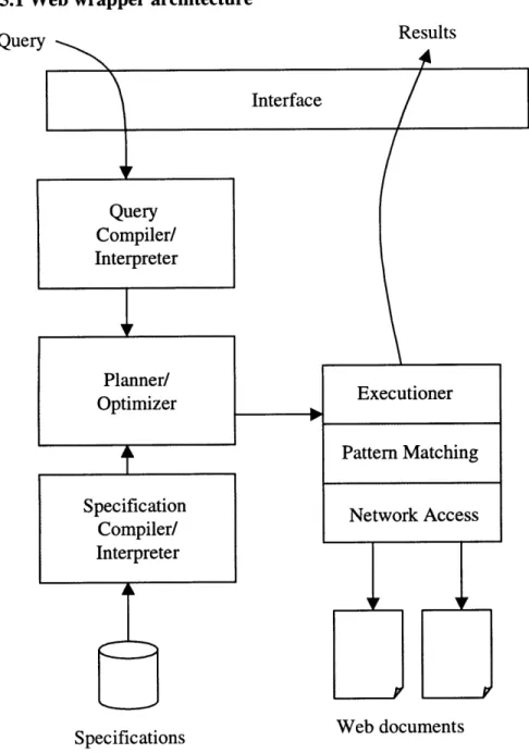
3.5.1 Web wrapper architecture Query Interface Query Compiler/ Interpreter Planner/ Optimizer Specification Compiler/ Interpreter Specifications Executioner Pattern Matching Network Access Web documents
Figure
5:
Web Warpper Architecture
Figure 5 shows the architecture of the web wrapper. The system takes the SQL query as input. It parses the query along with the specifications for the given web site. A query plan is then constituted. The query plan contains a detailed list of web sites to send http requests, the order of those requests and also the list of documents that will be fetched from those web sites. The executioner then executes the plan. Once the pages are fetched, 39 Results
the executioner then extracts the required information from the pages and presents the collated results to the user.
3.5.2 Wrapping a web site
For our query, the relation quote is a web quote server that we access using our web wrapper. In this section we will briefly talk about how a web site is wrapped. In order to
wrap a site, you need to create a specification file. This file is plain text file and contains
information like the exported schema, the URL of the web site to access and a regular expression that will be used to extract the actual information from the web page. In our example we use the CNN quote server to get quotes. A simplified specification file is included below:
#HEADER
#RELATION=quotes
#HREF=GET http: //qs. cnnfn.com
#EXPORT= quotes.Cname quotes.Last #ENDHEADER
#BODY #PAGE
#HREF = POST http://qs.cnnfn.com/cgibin/stockquote? \
symbols=##quotes. Cname##
#CONTENT=last:  \
</font><FONTSIZE=+l><b>##quotes.Last##</FONT></TD> #ENDPAGE
#ENDBODY
The specification has two parts, Header and Body. The Header part specifies information about the name of the relation and the exported schema. In the above case, the schema that we decided to export has two attributes, Cname, the ticket of the company and Last the latest quote. The Body Portion of the file specifies how to actually access the page (as defined in the HREF field) and what regular expression to use (as defined in the
Once the specification file is written and placed where the web wrapper can read it, we are ready to use the system. We can start making queries against the new relation that we just created.
Chapter 4
4. Building an Application
In this chapter we talk about how to build an application for the COIN system. We use the scenario built in the previous chapter of a stock analyst doing research on some security. She has four data sources from where she explicitly needs to access information. The stock analyst, as a user, is unaware of the fact that there are cases when the system accesses data sources implicitly without her ever specifying them in her query. An example is the currency exchange data source. The user never specifies if or when or even what data source the system should use. In fact she is not even aware of the fact that a currency exchange data source is used to convert currencies. This is handled by the system. When the system detects a conflict that involves currency conversion, the system automatically calls the intermediary currency conversion data source to resolve the conflicts. While the user is unaware of these intermediary data sources, the application developer needs to be
aware of these sources and needs to program the system to handle those conflicts.
The process of developing a COIN application can be broken down into various steps. * Pre-application setup.
* Domain model definition * Identification of the sources. * Source and Relation Definition. * Elevation of the data sources. * Addition of integrity constraints.
* Context definition for each data source. * Addition of conversion functions. * Application generation.
Once all the above steps are completed and the program debugged, we are ready to run the system. In the following pages, we will discuss each step in detail as we build a COIN application using the example scenario from of a stock analyst gathering information for her report that we mentioned in the previous chapter.
4.1 Pre-application Setup
In this stage we set up the structure where we are going to build the application. The first thing that we do is come up with a unique name for the application. In our case, we choose to call the application tasc. Once we have decided on a unique name, we create a new directory where we will place all the application files. The name of the directory, by convention is the same as the name of the application. We need to make sure that this directory has enough disk space to hold all the application files plus the application binaries created by the system. In addition to the above, during query processing, the system uses this directory to keep the intermediate results. The exact size requirement varies from application to application and the type of query and the size of data set being queried, a reasonable size is upwards of ten megabytes.
One more things that needs to be done as part of pre-application setup is copying the file
"basics.chr" from the examples directory into the current directory in which the
application is being built. The file "basics.char" contains basic rules for constraints that are applicable to all applications. For a detailed discussion on integrity constraints, please look at section 4.6. Once the file is copied into the newly created directory, the pre-application setup is completed and we can move to the next step.
As we walk through the application definition process, we create a set of files that contains all the application definition code. However, if the user needs to define some additional prolog code that they want to use in the system, they can define that in the file
userdefined.coin. The code defined in the file userdefined.coin is becomes part of the
4.2 Domain Model Definition
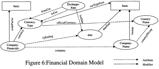
Before we start writing a new application, we need to define the domain model that will be used for that application. Figure 6 describes the domain model used in the example application that we are going to build. We call this financial domain model since the stock analyst is trying to gather financial information about a company. In the figure below, we have two types of objects, basic objects (denoted by squares) and semantic objects (denoted by ellipses). Basic objects have scalar types. Examples are numbers and strings. The semantic objects are the ones that are used in the system as they carry rich semantic
information about the objects in a given domain. In addition, there are two types of relations specified between the objects. These are:
* Attribute Relation * Modifier Relation
These relations are explained in Chapter 4. One thing to note here is that in Chapter 4, in addition to the two types of relations mentioned above, we had a third type of relation called inheritance relation. That relation does not show up during application development phase as this relation is more of a conceptual relation and is handled by higher-level design tools. By the time we reach at the level of application development we are at, the inheritance relationship is flattened out by the higher level tools.
. . . .
C r cm%-- -
County--- --- Attbute
..
ompany
Figure 6:Financial Domain
Model
ModifierUsing Figure 6 as a guide, we define the domain model for the COIN system. In a file called dm.coin, we define each object and declare its type. In addition to the object