A Design for Self-Assembling Robots in a System by
Myunghee Kim
M.S, Korea Advanced Institute of Science and Technology (2004) Submitted to the Department of Mechanical Engineering in partial fulfillment of the requirements for the degree of
Masters of Science in Mechanical Engineering at the
MASSACHUSETTS INSTITUTE OF TECHNOLOGY June 2006
@ Massachusetts Institute of Technology 2006. All rights reserved.
Author ... ...
Department of Mechanical Engineering May 12, 2006
Certified by... ... ... Rodney Brooks Panasonic Professor of Robotics Thesis Supervisor
Certified by ... .... .. .~... . John Leonard Associate Professor of Mechanical and Ocean Engineering Thesis Reader
Approved by ... ... ...
...-...-Lallit Anand Chairman, Dept. Committee on Graduate Students
MASSACHUS• ETSINSTTUTEL"
OF TECHNOLOGY
JUL 1 2006
ARCHIVES
-1-A Design for Self--1-Assembling Robots in a System
By
Myunghee Kim
Submitted to the Department of Mechanical Engineering on May 12, 2006, in partial fulfillment of the
requirements for the degree of Master of Science
Abstract
This thesis presents the design, construction, control, and application for a novel concept of self-assembling robots in a system. The system is composed of multiple cooperative robots that are designed to self-assemble in a system, execute manipulative tasks, and self-repair, all without human assistance. The self-assembling feature employs four mechanical design guidelines: independent module, one touch assembly design, self-alignment, and self-guiding. The independent design feature also employs independent motor control boards and a wireless communication board. For a decoupling effect, we chose a motor with large gear ratio. For safety and modularization purpose, we implemented a newly designed Series Elastic Actuator to limit shock bandwidth by using its compliance and sense forces during manipulative tasks. This thesis introduces a control algorithm, according to design parameters. With the results of dynamic simulations, we developed a preliminary algorithm for picking up a based on subsumption architecture. Finally, we verified the design and algorithm via an application, picking up a module in unstructured environments.
Thesis Supervisor: Rodney Brooks Title: Panasonic Professor of Robotics Thesis Reader: John Leonard
Title: Associate Professor of Mechanical and Ocean Engineering
-4-Acknowledgements
I would like to thank my advisor, professor Rodney Brooks, for his advising to the new robot world. I also would like to thank my reader, professor John Leonard, for his supporting my work.
Surely, I also would like to thank to humanoid lab researchers, who have helped me over the year. I have appreciated to Lijin, Varun, Jeff, Aaron, Eduardo, Charlie, Brian and Jessica for all of the help. I feel great thanks to Lijin for the proofreading and all the help. I also would like to my family, always trusting me. Special thanks to cha.
-6-Contents
1.Introduction ...
13
1.1 Concept for Self-Assembling Robots in a System... ... 13
1.1.1 Manipulation and Torque Requirements ... ... . 14
1.1.2 Self-Reconfiguration and Self-Repair ... ... 15
1.2 O ur A pproach... 16
1.3 Scope of Investigation... ... 19
1.4 Review of Thesis Content... 19
2. Literature Survey ...
21
3. M odular Robot Arm for Easy Assembly Design...
25
3.1 Actuator Consideration ... 26
3.1.1 R obot D ynam ics ... ... 26
3.1.2 Simulation Results and Actuator Selection ... 32
3.2 Easy Assembling Design ... 37
3.2.1 One-Touch Assembly Design ... ... 37
3.2.2 Three Selfs: Self-Alignment, Self-Locking, and Self-Guiding Designs... 42
3.3.1 Module Unit Design... 44
3.3.2 Electronics Design ... 48
3.4 H and D esign... 48
3.4.1 Mechanical Design ... 49
3.4.2 Electronics Design ... 52
-7-4. M odule M odeling and Control ...
...
55
4.1 One Module Modeling and Control: Force... ... 55
4.2 One Module Modeling: Position... 60
5.
Picking up a M odule ...
... 67
5.1 A lgorithm ... 67
5.2 High Level Control System ... 72
5.3 Experimental Results ... ... 76
6. Conclusions ...
79
6.1 Review of Thesis... ... 79
6.2 Further Work... 80
-8-List of Figures
Figure 1-1: A concept for a self-assembly robots in a system ... 15
Figure 1-2: Self repair in a system ... ... 15
Figure 1-3: Self-reconfiguration in a system ... ... 15
Figure 1-4: A possible assembly process... 18
Figure 3-3: Path of the end effecter and angular velocity of each joint ... 35
Figure 3-4 Torque of each joint ... 36
Figure 3-5: Cap instead of a bolt... 39
Figure 3-6: Detailed pictures: (a) spring fixture (b)cap for assembly ... 39
Figure 3-7: Assembling procedure... 40
Figure 3-8: Stress A nalyses ... ... 42
Figure 3-9: Self-alignm ent ... ... 43
Figure 3-10: Arm configuration ... 44
Figure 3-12: Series elastic actuator and force sensor... ... 46
Figure 3-13. Force sensor: (a) Front view (b) Side view (C) Measuring electronics... 46
Figure 3-14: SEA experimental result -linear fit between torque and measured value.... 46
Figure 3-15: Final design ... ... 47
Figure 3-16: Hand with acme nut and screw. ... ... 49
Figure 3-17: H and-pad design. ... ... 49
Figure 3-18: Basic model for finger pad force analyses ... 51
Figure 3-19: Finger pads for force and applied position analyses ... 51
Figure 3-20: Hand pad force sensing value ... 52
Figure 3-21 .Hand view - can handle one unit without any motor power... 52
-9-Figure 4-1: M odule m odeling ... ... 56
Figure 4-2: Schematic for module environment interaction ... . 56
Figure 4-3: Load side view ... . 56
Figure 4-4: Force control loop. ... ... 59
Figure 4-5: Experiment result - stiff wall with high gain ... .... 60
Figure 4-6: Experiment result - stiff wall with low gain ... 60
Figure 4-7: Closed loop system for position control. ... 61
Figure 4-8: Angular velocity comparison ... ... ... 62
Figure 4-9: Force sensing value comparison ... ... 62
Figure 4-10: Force sensing value comparison. ... ... 63
Figure 4-11: Angular velocity comparison of the second module ... 63
Figure 4-12: Force reading value of the second module... 64
Figure 4-13: Force sensing value of the second module... ... 65
Figure 4-14: Force sensing value when the robot plays with an object ... 65
Figure 5-1: Graphs of joint angle and joint torque when the arm is moving ... 68
Figure 5-2: Linear model of joint angle and torque ... ... 70
Figure 5-3: Linear fit of force and angle when arm... ... 71
Figure 5-4: Force reading value ... .. 71
Figure 5-5: Compensated force reading value ... 72
Figure 5-6 Data of angle read when the robot plays with an object ... 72
Figure 5-7: Control system for searching and gripping an object. ... 74
Figure 5-8: Control system for searching and gripping an object - One module... 74
Figure 5-9: Control system for searching and gripping an object - Two modules ... 75
Figure 5-10: Snapshots of grip an object ... ... ... 76
Figure 5-11: Snapshots for gripping a module - gravity effect ... 77
-10-List of Tables
Table 3-1: Module unit actuator specification ... ... 33
Table 3-2: Max torque, angular velocity, and power ... 33
Table 3-3: Design For Assembly (DFA) guidelines[ 16] ... 37
Table 3-4: Design consideration for a cap and a fixture ... . 39
Table 3-5. Zigbee specification... ... 48
Table 3-6: Actuator specification used in the gripper... ... 53
Table 5-1: Torque term comparison. ... ... 68
12-Chapter 1
Introduction
1.1 Concept for Self-Assembling Robots in a System
Recently, there has been growing interest in robots that can perform tasks in unstructured environments [1, 3, 4]. Some researchers have focused on manipulation in unstructured environments for performing manipulative tasks such as gripping an object and assembling objects without previous information. Some others have concentrated on developing self-reconfiguration robots which can change shape according to the environment. The reconfigure ability can be used for self-repair when a robot is broken.
This thesis introduces a novel concept: self-assembling robots in a system to achieve both autonomous and robust purposes. The system is composed of many robots which can do manipulation tasks, assemble, repair, and reconfigure another robot in a system as shown in Figure 1-1, 1-2 and, 1-3. For robots to perform tasks without human supervision, both manipulation and repair abilities have important roles. This ability is essential, especially when the working environments are too harsh for humans. While a robot is performing tasks, the robot can break. If the robots have repair ability, then they can perform tasks continuously. This chapter briefly introduces both concepts, manipulation and self-repair, and introduces new concept, self assembling robots in a system.
13-1.1.1 Manipulation and Torque Requirements
For manipulation tasks, robot actuators should satisfy at least the minimum torque requirements. Usually, the output torque of an actuator and the size of the actuator have a linear relationship. Large torque actuators have large sizes and masses. Consequently, the sizes and masses require large torque actuators. Because of this loop, it is desirable to implement actuators of small size and high power. For these requirements, (Zinn, M., Khatib, O., Roth, B., and Salisbury, J.K.) reviewed several kinds of actuators, including pneumatic, hydraulic, and DC motors. Hydraulic actuators have large torque capabilities, but they are too stiff to be used for safe and flexible robot - environment interaction. Pneumatic actuators have a compliance characteristic, but the large size actuators for the torque requirements makes them not applicable for a small modular robots[4]. One possible choice is to use geared DC motors because of their torque capability and small size. In addition, large gear ratio sets can reduce disturbance when a robot executes position control with an encoder; therefore, a motor combined with large gear ratio and an encoder will be appropriate for small spaces when precise position control is not required.
For robots to manipulate objects in any environment, compliance is an important issue [1, 2, 3]. When interacting with environments, robot compliance limits impact force band width, especially when the robot is built with motors combined with large gear ratios. In addition, compliance actuators can protect the gear from shocks provided by the environment. To provide passive compliance preventing any shock when electronic parts malfunction, (Matthew M. Williamson) has introduced the Series Elastic Actuator (SEA) [2].
Robots interact with environments that have non-negligible inertia by using both position and force information. By observing the relationship between robots and environments, (Neville Hogan) introduced impedance control [5]. By using SEA, the robots can acquire force or torque information; therefore, impedance can be controlled easily. Even though the SEA has low band-width, it is high enough to mimic human motions. Therefore, SEA would be an optimal choice for the robots to perform human mimic motions.
-14-Assembly robot & pool of parts
Work robots (suitable shape)
rn
-~Figure 1-1: A concept for a self-assembly robots in a system: A robot arm assembles another robot arm by using parts in a multiple robot system.
Figure 1-2: Self repair in a system: A and B are robot and they are in the same multiple cooperative robot system. B has a defected module, which is colored as red. B sends a
help signal, A can fix B.
Figure 1-3: Self-reconfiguration in a system: The system has a robot and many modules. If there are obstacles, then the robot can make another robot with modules to avoid
obstacles.
-15-A
B
O.
iLU
A
VMM
hll sl PPn~q·lown
lsoft
~egpl~ Ir, ws~1.1.2 Self-Reconfiguration and Self-Repair
One easy way to repair robots would be to replace a defective module, assuming that the module can function independently and has the same shape as shown in Figure 1-2. When a person fixes a machine, if the machine is composed of modular parts, the first trial would be to substitute a new module for the one that appears to be broken. Exchanging modules reduces repair time, and also gives the opportunity for a novice to fix the machine. Robots have lower manipulative ability than even some novices in unstructured environments. However, if the robots are made of the same module, robots can repair themselves almost effortlessly like humans. For a robot, the module would be composed of an actuator, sensor, and electronic parts to control the motor and receive signals from other modules, as well as mechanical, electrical bonding parts to bind to another module. However, the existing SEA, which has a complex structure and large size, makes it hard for SEA to be built in a module. Therefore, a module design will be introduced with a new SEA design.
Many researches have focused on self-reconfigurable robots, which can perform tasks by changing shapes [3]. The robot can navigate environments by reconfiguring its shape to adapt to environments [3]. A robot, able to reconfigure shapes according to environments, can be viewed as an extremely compliant robot. Some researchers study effective active bond mechanism which can attach one module to another module without exterior help. However, implementing active bonding mechanism in an independent module makes it difficult to implement a large power actuator. With a small power actuator, it will be hard to accomplish manipulation tasks which require moving against gravity. As a result, this thesis introduces a new concept.
1.2 Our Approach
This thesis introduces a novel concept, self-assembling robots in a system (SRS). The system is composed of many robots, which can do manipulation tasks, assemble, repair, and reconfigure another robot in a system as shown Figure 1-1, 1-2 and, 1-3. Figure 1-4
-16-illustrates a possible assembly process. A robot with many modules, which have one degree of freedom in each module, can be regarded as an active agent. If the agent can execute tasks, then, at least, the agent can assemble another active agent. The assembling ability also allows for the agent to repair another agent or help to change shape. If the agent has enough degrees of freedom, it can repair itself or change its shape to adapt to the environment. Because one agent will assemble another agent, the agent does not need active bond mechanisms; instead, the agent can have a large power actuator, capable of manipulation tasks. However, the module still needs to have a modular and easy assembly design to assemble another robot easily. In addition, the agent can be very compliant with the SEA actuator.
As a method for motor control, simple varying gain local PID control is used to improve the system response for unstable system. Complicated control methods are usually applied when it is hard to change system parameters. However, because of the easy assembly design of this robot, changing system parameters is hand-down work, and this feature allows a simple control method. In addition, a motor combined with large gear ratio allows simple and uniform control methods regardless of the manipulator dynamics. Because of time delays during wireless communication, it is desired to implement control algorithm as locally as possible.
-17-Figure 1-4: A possible assembly process.
18-SRS with the compliant actuator will make it possible for the robots to manipulate in unstructured environments, repair themselves if there is any failure, assemble another robot if more robots are needed, and reconfigure themselves if there is any manipulation difficulty in a certain environment. With those abilities, the robots can be used in a harsh environment.
1.3 Scope of Investigation
Manipulation tasks have design constraints such as low weight and compliance because of motor power and size requirements, as well as protection from and to environments. Modular robots also have design requirements such as independent motor control boards, communication, and same shapes. For SRS, both manipulation and modular robot requirements should meet. Therefore, in this thesis, a modular design for SRS is intensely studied first. Then, to control a module, a robust and simple motor control theory is studied and implemented to a module. With the modules, the way to pick up another module without specific information would be introduced as a the first step to assemble another robot
1.4 Review of Thesis Contents
This thesis organized as follows.Chapter 2 provides a survey to support this work. Chapter 3 describes design procedures and results. Chapter 4 shows modeling a module and control
Chapter 5 describes an algorithm to pick up a module without specific information. Chapter 6 provides conclusions.
-Chapter 2
Literature Survey
This chapter reviews related work on self-reconfigurable robots, self-assembly design, actuator consideration, and algorithms. Many research efforts involving self-reconfigurable robots are concentrated on developing mobile robots or forming geometry
shapes [10, 11, 12, 13, and 14]. For self-assembly ability, many have explored various modular hardware [10, 11, and 13]. For example, the crystal and the corona robots have bonding mechanisms on four surfaces and the i cube has active links, which have three degrees of freedom [10, 11, and 13]. Based on the characteristic, these robots are largely divided into two categories: a lattice type and chain type. Like the crystal, the lattice type generally has merits on self-reconfiguration, and the chain type has strong points on manipulation. They are also self-sufficient because they have their own processors, power supplies, communication systems, sensors and actuators. Some of the self-reconfiguration robots have passive structures [15]. Because of their bonding mechanism, they are typically large. These robots have tremendous potential for the tale of self-assembly, reconfiguration, repair, and navigation. However, with the small sizes actuator compared to their own size, it is still difficult for these robots to perform manipulative tasks.
(Whitney) found that in general, the torque required to move a mass M at the end of am arm of length L in time T is proportional to ML / T2 [ 16]. As the arm length is long, and
mass of arm is heavy, the arm needs a larger actuator. There have been many efforts in reducing the size of arm robots. To reduce masses near the end effecter, some robots have
-21-actuators on their shoulders [1]. Some of modular robots succeed to reduce sizes and mass by using relatively small actuators [6]. The Light Weight Robot has been succeeded in raise the ratio of the load to its weight more than one. Several actuators were reviewed in terms of safety and torque density [4]. In seawater hydraulic actuators, a rotary actuator is used because of their compact size and high torque density [17].
Another issue for robot design is safety. It is difficult to acquire a desired torque by using the motor itself. Since a motor combined with a large gear ratio can deliver a shock to environment, a Series Elastic Actuator has been introduced as a way to limit shock bandwidth [2]. Several robots use the basic concept of Series Elastic Actuators [1, 2, 4]. Because of limited band-width, these robots have low speed performance. To improve this performance, alternative actuator method is introduced: the base is driven by SEA and the end-effecter is driven by DC motors [4]. The Light Weight Robot (LWR) does not use the SEA, but has intrinsic compliance because of its material property [6]. (Sugar) also made a new actuator using a spring for compliance and force control [18].
Because of the compliance, the robot can be unstable; therefore, several analysis and control methods have been proposed [18,19, 20] Sugar shows one module modeling with his proposed new actuator. The Light Weight Robot (LWR) is controlled by a passivity based Cartesian impedance controller. However, in general, with low gain PID controller, the robots with SEA show stable behavior.
As a robot control method, joint torque control method has been proposed to avoid complex inverse dynamics [9]. By using direct drive motor, he implemented joint torque control [8]. LWR also uses joint torque control to control a robot.
For manipulative tasks interacting with the environment, impedance control has been proposed [5]. The SEA can be used a force sensor, allowing force control to be performed for manipulation in unstructured environments [1]. The joint torque controller, shown above, is also used for force control [18,19]. However, the basic difference between them is the open loop characteristic as discussed in the paper, a new actuation approach for human friendly robot design [4]. When uncontrolled, the SEA can reduce shock bandwidth greatly. Even though SEA has low speed characteristic, it is fine for application like human walking.
-Assembly is also important. (Whitney) wrote a book about assembly process. In the book, he argued that four features are important: reducing the number of components,
ample space for insertion tools, inserting parts from above, and making it obvious the method of assembly. He also argued that force sensing is important in the assembly process and he provides force sensing charts during assembly. In addition, in the book, he argued that the assembly process should be range from gross motion to fine motion [4]. (Asada) shows effective combinations of robot configurations in terms of necessary joint torque [8].
To achieve desirable behavior, several algorithms have been studied. For self-reconfiguration robots, generic distributed assembly and repair algorithms are studied by using cellular automata [14]. The algorithm is abstract, and they attempt to implement the algorithm independent of hardware [14]. For real robots, Brooks argues that the robot should be situated and embodied. He proposed the subsumption architecture, a behavior-based architecture. A behavioral language has been made by using primitives and implemented to the cog[22].
-Chapter 3
Modular Robot Arm for Easy Assembly
Design
In this chapter, a modular robot arm design for easy assembly is introduced. Even if modular robots have difficulties in acquiring high efficiency, in terms of the ratio of their mass to manipulating objects, the Light Weight Robot (LWR) at Deutsches Zentrum flir Luft- und Raumfahrt e.V. (DLR), specifically designed as a light-weight and high performance robot with above one its own mass to object ratio, shows a possibility that modular robots can be developed to perform tasks efficiently [6].
To perform manipulation tasks, a robot arm needs to have at least six degrees of freedom. To avoid obstacles and show natural motion, it is desired to have redundant degrees of freedom. Therefore, for actuator selection, seven degrees of freedom for a robot is considered, which is one more degree of freedom than is necessary. To reduce weight, the modules for this robot are classified by two types: one for positioning tasks and the other for orientation tasks as shown in Figure 3-1.(The figure shown in here is the first version.)
The first four modules are designed for positioning tasks and the end three modules are for orientation tasks. For the modular robot design, first we chose actuators, having enough power requirements. According to design constraints, this thesis introduces several easy assembling designs. We also developed a new SEA design and force sensing designs.
-Figure 3-1: A robot arm consisted of two kinds of modules.
3.1 Actuator Consideration
. As mentioned in Chapter 1, when a robot performs manipulative tasks, it moves against gravity. The gravity constraint requires higher power actuators than those used for planar motions. In this chapter, the robot dynamics is considered for actuator selection. Several simulation results are shown by using selected actuators. The simulation is performed by assuming that all the modules are the same mass and configuration as the developed robot until now. For an actuator selection, it is assumed that each joint has infinite stiffness.
3.1.1 Robot Dynamics
Robot dynamics equations have been derived by using Lagrange method [9]: From the equations below:
-K= i=lT [m ci Jci +Jwci i ci nVgT V = g . rcim i i=1 L=K-V a aL aL i 8t a4i qi
(Where, L represent Lagragian, K represents Kinetic Energy, and V represents Potential Energy.)
The robot dynamic equation is derived:
M(q)q + C(q, q)i + g(q) = where D= , mi i=1 ci nl c L 1C
kj i=1 2
(J: Jacobian matrix d.: ij component of D matrixJvi + JoiT RiiRi
ci
ci
TJc1
.dkj &dki 8qi aqj
adkj adk,
aqi aqj aq k ad k iaq
k
R: Rotation matrix c, k,j componet of C matrix.) -27-(3-1)
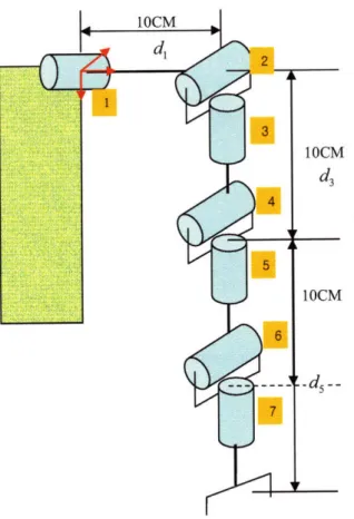
Figure 3-2 Schematics for robot dynamics calculation with seven modules.
Figure 3-2 shows a schematic, which is used when solving dynamic equations. By using the above equations, the equation (3-1) is derived from the following coefficients:
DII D
12 D13 D14 D21 D22 D23 D24 D31 032 D33D41
D42 D43 D44G[
G =
G2
-G4--28-C11 Cl C31 C41 12 C22 32 42 13 C23 C33 C43 14 C24 C34 44 Where,
D,
m5d + m3d32 cos2 q2 + m4d2 cos2 q2 + m5d2 cos2 q2 - 2m5d5d3 sin q2 cos q3 cosq2+ md 2
cos2 q2 cOS2 q4 - 2msd~ sin q4 sin q2 cos q3 cosq2 cosq4 - m5d cos2 q4
2mddq2 2 co 2 2
2mdd cos2 2 COsq4 -md cos2 3 + m5d cos q cos q4 cOS2 q2
D12 = -msd5 sin q4 sin q3(dd sin q4 cos q cos q3 + d sin q2 cosq4 + d sin q2)
D43 = -msd s sin q4(d, cos q2 cos q4 cos q3 + d3 cos q2 cos q3 - d sin q4 sin q2
Dl4 = -msd, cosq2 sin q3(d3 cosq4 + ds)
D2, = -m5d, sin q4 sin q3(d, sin q4 cosq2 cos q + d5 sin q2 Cosq4 + d3 sin q2)
D22 = m5d + m3d 2 + m4d2 + mqd 2 cOs q4 + 2msdsd cosq4
5d cos5d2 2 COS2 3 c S2 q3 4
D23 = -mnd 5 sinq4 sin q3(d5 cosq4 + d3)
D24 = m d, cos q3(d3 cosq4 + ds)
D,, = -m5d5 sin q4(d cos q COs q4 COs q3 +d3 cosq2 cosq3 - d sin q4 sin q2)
D32 = -ms5d sin q4 sin q3 (ds cos q4 + d3)
D03 = m5d5 sin2q
-29-D34 =0
D4 1 = - 5d5 cos q2 sin q3 (d, cos q4 + d5)
D41 -= m5d, cos q3 (d3 cos q4 + d5 )
D43 =0
D44
5dAG, = g[-m3d3 sin q, cosq3 - m4d3 sin q, cos q2 + m [ {(sin q, sin q2 cos q + cos q, sin q3) sin q4
-sin q, cos q2 cos q4}d5 - d3 sin q, cos q2]
G2 = -g cos q, (m3d3 sin q2 + m4d3 sin q + md5 cos q2 cos q3 sin q4 + md5 sin q2 cos q4 + md 3 sin q2)
G3 = gmd, (cos q, sin q2, sin q3 + sin q, cos q3) sin q4
G4 = gm5d, {(-cos q, sin q2 cos q3 + sin q sin q3) cos q4 - cos q cos q2 sin q4
1 1
C,I = -mAsdd , sin(q4 + 2q2 q3)+ msdd3 sin(2q2 q3 -q 4) -- msdd3 sin(2q2 -q3 4)
2 2
1 5 1
+-m1,d, sin(2q2 + 2q3)-5 m d5 sin(2q2+ + 2q4)+ md sin(2q2 3 -2q 4
4 8 8
3 1 1 3
-- msdn sin(2q2 -q 3+ 2q4)+ msd sin 2q3 -- m5dd 3 sin(2q2 -q 4) -- msdd3 sin(2q2 +q4)
8 -4 2 2
1 3 1
-- md2 sin(2q
2 3 -2q4) - 5d sin(2q2 + 2q3 + 2q4)+ - 5d sin 2q4 - 3d sin 2q2
8 16 4
-m4d sin2q2 5d in2q - md sin (2q3 + 2q4 1 m5 d sin(2q2 + 2q3 - 2q4)
- dsin24 16
1 1 3 2
- msd sin(2q2 -2q 3 +2q4) m 5d2 sin(2q2 - 2q3 - 2q4)--m 5dSin(2q2 +2q4
16 16 4
1
Smsd2 sin 2q2 -m5dd3 sin q4
4
-30-C12 =2msd2 sin q2 sin q3 -4ms5dd 3 sin q4 cos2 q2 cosq3 -2m5d2 cosq2 cos2 q4 sin q2
-4m 5d5 cosq2 cos
2 q
4 sin q2 + 2md 2 cosq2 -2md sin q4 sin q3 cos q2cosq4
- 2m5 d5d3 sin q4 sin q3 cos q2- 4mdd 5 cos q2 cos q4 sin q2 + 2mndd cos2 q2 sin q2
- 2m5d2 cos2 q3 cos2 q4 cos q2sin q2 -2m d5 cos q4 sin q3sin q
4 cos q2 cosq3
- 2msdA cos q4 sin q3 sin q2 - 2m3d3 cosq2 sin q2 - 2m4d3 Cosq2 sin q2 - 2msd2 cosq2 sin q2
-2m 5d cos q2 COs2 q3- 2m5d2 cosq2 COS2 q4 + 2mnd 2 c coq2 q4 cos2 q3 +2m5sdd 3 sin q4 cos q3 + 2m5dA sin q4 cos q3 cos + 2m5d sin q3 in q2 COs q
- 2mnd 2 sin q
3 sin q2 cos q3 cos2 q4
C,3 = -2dsm 5 (-d3 sin q4 sin q2 sin q3 cos q2 - d, sin q4 sin q2 sin q3 cos q2 cos q4
-d 5 cosq3 cos2 q2 sinq3 +d5 cosq3 cos2 q4 cs2 q2sinq3-d 5 cosq2 +d5 cosq2 cos2 q4 + d5 cos2 q3cosq2 -d 5 cos2 q3 cos q2 cos2 q4 -d sin q4 cos q2 cos q4 sin q3
-d3 sinq4cosq2sin q3 +d3 cosq2 cosq3 cosq4 +d5 cosq cos2 q4 cossq 3 -d5 cosq4 sinq4sin q2)
C14 = 2m5d5(d3 cos q4 sin q2 cos qos + d5 cos2 q2 cos q4 sin q4 + 2d5 cos2 q4sinq2 cosq3 cosq2
-d sin q2 cs q3 cosq2 -d cos q4 sin q4 + d3 cos2 sin q4 + d5 cos2 q3 cos q4 cos
2 q sin q 4
- d5 sin q2 sin q3 + d5 cos q4 sin q3 sin q4 cos2 cos q3 + ds cos2 q4 sin q3 sin q2 + d6 cos q2 COSq3 cosq4
- d5 cosq2 cos2 q4 cosq3-d5 cos q4 sinq4 in q2 -d 3 sinq 4cosq2 sin q3)
11 1
C22 5=-md22 sin 2q, + mS2 d sin(2q3 +2q4 )--m d sin 2q
4 -2msdd3 in q4
2 2 2
23 = -2md 5(d5 cos2 q
3 cosq2 -d 5 cos2 q3 cosq2 cos2 q4 + d5 sin q4 cosq3 sin q2 cosq4
+ ds3 sin q4 cos q3 sin q2 + d cos q3 sin q3- d cos q3 cos2 q4 sin q3+ d5 sin q4 cos q3 Cos q4
+d3 sinq4 cosq3 +d, sinq 3 cosq4 +d5 cos2 q4 sin q3)
C24 = 2m5d5 (-d, cos q4 sin q3 sin q4 cos q2 cos q3 - d cos2 q4 sin q3 sin q2 - d3 cos q3 sin q3 sin q2
-d5 cos q4 sin q4 -d 3 sin q4 +d5 cos2 q3 cos q4 sin q4 - d3 sin q3 cosq4 -d5 cos2 q4 sin q3
-d 3 cos q3 sin q4)
C(3 = msdJ sin 2q4
-C34 = -2msd 2 (cos q2 cos2 q4 cos q3 - cos q4 sin q4 sin q2 - cos q2 cos q3 + cos2 q4 sin q3 - sin q3
- cos q4 sin q4)
C44 =0
Since C and D matrix are symmetric, DY, = Dfi and C, = Ci.
(Where mi: mass of ith module except m5 (m5 = m, + + 7 + mLoad
q,:joint angle of ith module
d,: length of between module (as expressed in Figure 3-2)
When deriving these equations, moment of inertia terms were neglected since the module has 0.05 widths and 0.1 heights. As a result, multiplying these terms generates 0.01 order of magnitude compared to the mass term. As shown above, since the robot dynamic equation is too complex, several methods for fast computation have been studied [7]. However, we found that for low speed application, such as searching for a module and picking it up with low inertia, the quantity of inertia and coriolis dynamics terms are much smaller than the quantity of gravity terms. In chapter 4, a picking up a module application is introduced by using this property.
3.1.2 Simulation Results and Actuator Selection
After several trials and errors, we selected DC motors as our final actuator. In this chapter, several simulation results are shown using the selected actuators. It should be mentioned that the highest torque of the first actuator does not meet the torque requirement, because in this simulation I assumed that all the modules are composed of the same module. However, if the arm is moving in a narrower range, i.e., near the ground, then the torque requirement is still met because the torque is directly related to the gravitational torque. For simulation, both the swaying of one joint and the following a path were performed. This thesis shows the simulation results of following a path. The robot follows several
-32-Table 3-1: Module unit actuator specification.
Continuous Angular Permissible Power
Torque Output Velocity Torque Output
Module Unit 1.8 Nm 47 rpm 2.7 Nm 12 watt
Actuator
Table 3-2: Maximum torque, angular velocity, and power from the simulation results.
Max Torque Max Angular Max Power
Velocity
Uniform module 4.9 5.0 8.8
Two kinds module 2.7 1.8 5.2
line paths, 40cm long in 2 sec. Table 3-1 shows the specification of selected actuators and torque requirements. For actuators, DC brushless motors are used because they have high power density and compact size, as mentioned in Chapter 1. DC brushless motors are also relatively easier to control than AC motors. After several trials and errors, the motor and module size are decided using three important design constraints
* The motor voltage must be operated by battery * The motor must use the large gear ratio
* The motor size should be minimized.
The importance of the large gear ratio will be shown in the next chapter. The motor size directly relates to a module size. The actuators for a gripper will be discussed in the next section. By using two kinds of module, the robot can cover a large work space.
The following shows the experimental results. The paths are chosen by using forward and backward kinematics equations.
Forward kinematics for Figure 3-2 is as follows:
dx = {(- cos q, sin q2cos q3+ sin q, sin q3sin q4+ cosq, cos q2 cos q4)d + d3cos q2
-33-dy = {(-sin q, sin q cos q3 - cos q sin q3 sin q4 + sin q, cos q2 cos q4)d, +d3 sin q, cos q2
dz = (cos q2 cos q3 sin q4 + sin q2 cos q4)d5 + d3 sin q2 + d.
Where, dx, dy, and dz are desired x, desired y, and desired z each.
To calculate the angle when a robot follows a path, inverse kinematics are also calculated.
If we calculate kI,
dx2 + dy2 + (dz-d,)2 -d5 -d,2
k,=
2d3d5
Then q4, the output angle of the 4th module is calculated as follows.
2-q4= tan-' k,
Since, the robot has a redundant system, q3 = 0 is assumed for this calculation.
Then, q2 and q, are calculated as follows:
q2 =tan` (d3 + d cosq4)(dz-d 1) -d 5sinq4 dx2 dy2
(d3 + d5 cos q4)4dx2 +dy2 (dz-d)d5 sin q41
q, = tan -'
dx
For simulation purposes to estimate the actuator capacity, the path is composed of cosine functions because this makes it easy to change the manipulating period. First, each joint angle is calculated according to the joint path, and then the results are used for the dynamic equations. Several simulation results are follows.
-34-Figure 3-3 shows a trajectory and the angular velocity of each joint. Fig 3-4 shows the inertia torque component, coriolis torque component, and gravity torque component in each joint. The mass of each joint was 500g, the module weight, and distance between joint was 10cm, the distance between actual modules. Finally, the load was assumed to be
500g. Using those values, the following simulations were performed.
Trajectory - • I I - " 0 •.• -- I i t- -- r-- i • I -- I I -0.05 ---- T I - I -0.1 ~--- --- I --0.1 -0.1• -- - - --0.2 --0.3 0.1 -.5 -0.4 0.1 0. 01 x coordinate, [m] 01-- Op]Outp0t 0.1 z coordinate, [m] 0 0.1 0.2 0.3 0.4 0.5 time, [sec] 0.6 0.7 0.8 0.9
Figure 3-3: Path of the end effecter and angular velocity of each joint.
-35-2.5 2 1.5 1 0.5 0 -0.5 -1 -1.5 41 --- I --- --- ---7 l - -- I I I --- I--- +----+--- 1--41---I -- -I - - -- ---I I I I I-_ I I I I I . I- II I -I -- 11----1---- -- T----T--- ----l
+-Joint 2 torque -- D(q)qdo g(q) Ttta Stotal .. - --- ey I N I t I [ 0.4 0.6 0.8 1 time, [sec] Joint 3 torque - D(q)qdot S g(q) I TtotaI -t LI L L 0 0.2 0.4 0.6 time, [sec] 0.8 1 0 0.2 0.4 0.6 time, [sec] 0.8 Joint 4 torque 0 0.2 0.4 0.6 0.8 time, [sec]
Figure 3-4 Torque of each joint.
As shown in Figure 3-4 for slow motions, the gravity torque is the most important part compared to other parts. Table 5-1 shows the ratio between the gravity part and other parts. These results were used to detect a module and pick it up. which is shown in the chapter 5. -36-0.2 -5 5 0 -5 Joint 1 torque I -\ J I
3.2 Easy Assembling Design
Just as novices can assemble Do It Yourself (D.I.Y.) furniture, novice robots can assemble robots designed to be easy to assemble. With robot modules specifically designed for easy assembly, robots can produce other robots while concentrating on manipulative tasks. At this point, easy-to-assemble designs play important roles. There is a lot of basic rules for an easy-to-assemble design, as shown in Table 3-3 [16].This section presents a one-touch assembly design, a self-alignment design, and a self-guiding design by considering those guidelines.
3.2.1 One-Touch Assembly Design
The most difficult part in an assembly process is the assembling itself. A child can assemble large Lego blocks because Lego blocks are designed to be easily put together. In contrast, some adults have difficulty assembling poorly designed D.I.Y. furniture with
Table 3-3: Design For Assembly (DFA) guidelines[16]
Minimize part count
Provide ample space for insertion tools or fingers
Design parts so that they do not tangle with each other
Insert parts from above
Make it obvious how to assemble
Can be assembled one-handed by a blind person wearing a boxing glove
Is stable and self-aligning
Tolerances are loose and forgiving
Few tools and fixtures
Parts easy to grasp and insert
-37-(Source: Whitney, Mechanical Assemblies: Their Design, Manufacture, and Role in Product Development. New York, NY: Oxford University Press, 2004.
screws and nuts. We want a robot to assemble another robot with minimal efforts.
Various approaches for assembling have been investigated [10, 11, 13, 16]. These designs are mainly divided into active assembly designs and passive assembly designs. Most self-assembling robots use active assembly designs, which employ another actuator. However, an additional actuator makes a module design complex and heavy and increases costs. With passive assembly designs, a robot can have compact form and light weight, but the robot needs an active agent to assemble the robot modules. The arm of a self-assembling robot in a system can be regarded as an active agent with manipulation capability; therefore, we can employ passive assembly designs. Many inventions with passive assembly designs are widely used such as women's hair pins; children's toys; school supplies with active agents, humans; and self-assembling robots. Most of them are mainly required to stand against forces or torques. However, the assembly design for a manipulation robot arm for self-assembling robots in a system needs to protect a robot arm against two directions of torques and three directions of forces.
We developed a new design to endure such forces and torques for the self-assembling robots with a 3-D printer, as shown in Figure 3-15. The design follows basic guidelines for easy assembly: as few parts as possible, champers, and large parts. The main idea is that instead of bolts and nuts, we used a cap to connect one part to another part, as shown in Figure 3-5.
We maximize the size of the cap on the module to permit easy assembly and to distribute force and torque. The large round part is employed mainly for the purpose of distributing two directional forces and one directional torque, as shown in Figures 3-5 and 3-8. The sizes of the motor and the Series Elastic Actuator (SEA) are the main constraints in this design. One large cap would not be enough to connect one module to another module rigidly. A screw mechanism would be a solution. However, to adjust the cap to the screw tap in another module, delicate force sensing is required. To reduce the screw mechanism, we designed two small projecting parts and one fixture with a spring, as shown in Figure 3-5 and 3-6.
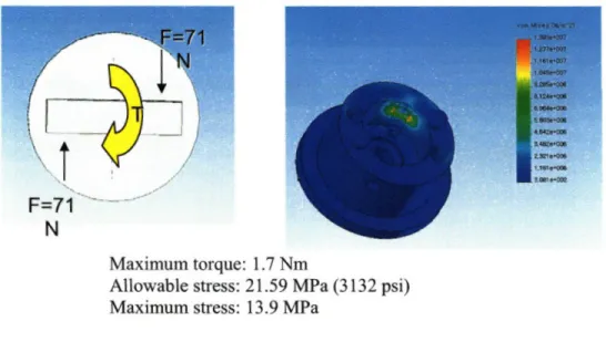
The two projecting parts are employed to resist a moment as shown in Figure 3-8(b). Figure 3-8(c) shows the fixture employed to resist a torque. However, the projecting parts and the fixture mechanism makes hard to attach one module to another; therefore,
-38-Figure 3-5: Cap instead of a bolt.
IL
--(a)
Figure 3-6: Detailed pictures: (a) spring fixture (b)cap for assembly.
Table 3-4: Design consideration for a cap and a fixture.
Configuration 1 spring w/o self 1 spring with 2 springs w/o sel 2 springs with locking self locking locking self locking
Swaying Yes No A little No
Locking force Enough Enough Enough Enough
Can handle stiff Can handle stiff Cannot handle Cannot handle
spring spring stiff spring stiff spring
Ease of Easy Moderate Hard Moderate
manipulation
(Yellow: Selected configuration)
-39-(a) (b) (c) (d)
Figure 3-7: Assembling procedure: (a) insert a cap (b) rotate the cap (c) once a hole in the module and projecting parts are matched; then the cap does not rotate. (d) finally a spring
fixture holds the cap firmly.
several design candidates were considered, and the optimum value is chosen as shown in Table 3-4.
Figure 3-7 shows an assembling procedure. The cap can be rotated until the projecting part of the fixture is fitted to the hole of the cap. Once the projecting part and the hole are matched, the cap does not rotate if the fixture is not pushed. Therefore, the cap and the fixture together can resist the rotating direction torque.
However, since the cap is made using ABS, the material used by a 3-D printer, basic stress analyses should be performed. To calculate the maximum allowable load, several stress analyses are performed using the dynamic equation results. There are several assumptions: lumped mass and no compliance. According to this dynamics, load stress analyses are performed by using the von-mises mechanism. The analysis results show that the module design with ABS is strong enough to sustain these force requirements, as shown in Figure 3-8. As a result, we can conclude that the assembly can endure three directional forces and two directional torques.
For the fixture, both magnets and spring systems are considered. Magnets usually rarely have enough force to maintain torque requirements. With a spring, and a tampered pusher, a robot can assemble another module by using one arm. Therefore, we call this design a one-touch design. However, this design needs two hands for disassembly. When disassembly is demanded, at that moment, since another robot arm is already assembled, robots can disassemble a third robot arm with two hands. With a hand-tuned spring fixture and a cap with two projecting parts and a hole, one module can be conveniently attached to another module.
-40-I E g a
I!
: ; : : :I IXUAtU
gI
Maximum load: 25 N
Allowable stress: 21.59 MPa (3132 psi) Maximum stress: 1.683 MPa
(a)
Fixed
Maximum moment: 1.89 Nm
Allowable stress: 34.4 MPa (4975 psi) Maximum stress: 5.57 MPa
(b)
-41-r-I1
N
Maximum torque: 1.7 Nm
Allowable stress: 21.59 MPa (3132 psi) Maximum stress: 13.9 MPa
(c)
Figure 3-8: Stress Analyses: This analyses show that the cap with two projecting parts can endure required torques and moments.
3.2.2 The Three Selfs: Self-Alignment, Self-Locking, and Self-Guiding
Designs
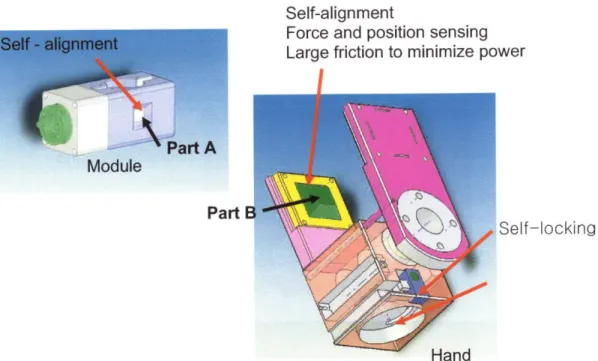
To augment the easy-assembling mechanism, we explore the self-alignment design. Well designed utensils have small holes so as to be gripped easily. Even though such utensils are designed for anyone to use, the compliance of a hand helps a finger to fit into the small hole. The compliance of an ABS material is far less than that of humans. Therefore, we designed the projecting part of the hand module and engraved part of a module to fit each other, as shown in Figure 3-9. In addition, we inserted springs inside the projecting parts in a robot hand to add compliance. The compliance also protects the hand from any shock given by the environment and also protects the environment from robot malfunction.
-42-Self-alignment
Force and position sensing Large friction to minimize power
I
Part
Self-locking
I ICII UJ
Figure 3-9: Self-alignment: Part A matches with Part B.
For manipulative tasks rather other than assembling a robot, another gripper will be used. Once the gripper is disassembled, it is hard to assemble another gripper. In addition, the small size of gripper makes it hard to implement the fixture, used in the module;
therefore, for the gripper, another motor with hall sensor is used for self-locking.
Instead of using vision systems, we implemented IR guiding sensors to give position information to the robot arm. A robot module broadcasts its own identification information, and once a robot arm receives the information, the robot arm approaches the robot module and picks up the module by virtue of the directionality of the IR sensors. Figure 3-10 shows final arm design with three modules including a gripper, (a hand).
43 -Part
Manipulation Force Sensor
-)For feeling units -For compliance Self alignment IR sensor -4 Guiding
/
Self alignment -)Easy assembly -)Grip force Ilanipulationactile Sensor and pring
)For feeling units •>For compliance
Self Locking Between units -)Easy assembly.
a
Figure 3-10: Arm configuration.
3.3. Force Sensing and Modularization
Humans mostly use force information when gripping objects and have compliance, thus limiting shock bandwidth. With joint torque controls, we can avoid noisy inverse dynamic equation calculation. A modular and compact design is also required for SRS. In this section, a new compact SEA actuator and force-sensing compliance hand pad will be introduced for the purposes of force sensing and compliance.
3.3.1 Module Unit Design
A traditional SEA requires a large space to be implemented in and has a complex structure. The concept of SRS is to attach another module when an additional degree of freedom is required. It is desired to have a SEA as small as possible and light in weight
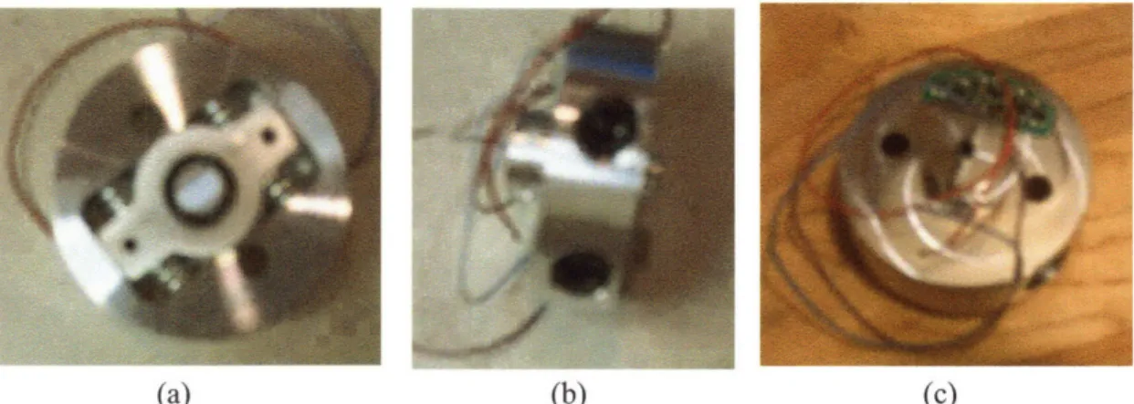
-44-because large size and heavy weight mean that a module has a large moment of inertia. The characteristics are directly related to the large actuator, as shown Section 3.1. To meet those requirements, a new force sensor for the SEA was designed. It is round and full of springs, as shown in Figures 3-12 (b) and 3-13. To measure spring displacement, magnets and Hall Effect sensors are used. Figure 3-12 shows the new design of SEA actuator and Force Sensor. It has ± 20 deg range of motion. Applied torque and reading value have following relationship:
F= F -F
2
+F-F =4kax
(3-2) T = FI = 4kx
where ax is a moving range, k is a spring constant, and I is a distance between the center of SEA and a spring. Ax can be determined by the read voltage. Then, we can find the applied torque or force. This relationship is further verified by experiments.
The force sensor has a linear relationship between load and voltage read value, as shown in the Figure 3-14 graph,. The experiment was performed by adding a mass at the end of a long bar attached to the outside of the SEA, and measuring the output voltage, which is the Hall Effect sensor reading value. The x axis of the graph shows the amount of mass which directly relates to torque by multiplying bar length, and the y axis shows the hall sensor reading value which shows measured voltage value. The graph shows the linear relationship between applied torque and hall sensor reading value. R2, which
represents the goodness of the linear fit, shows 0.99. In fact, the linearity is restricted not by round shape but by the hall sensor's sensing range. One can change stiffness easily by using screws, shown in Figure 3-13 (b). Assuming a linear relationship, force sensing value is approximated as shown in Equation (3-2).
-Force Sensor
(a) (b)
Figure 3-12: Series elastic actuator and force sensor.
(b) (c)
Figure 3-13. Force sensor: (a) Front view (b) Side view (C) Electronic instrument.
Sensor Reading (Until 2.9Volts) Y = 0.0896x + 1.6188
R2= 0.9902 2.9 2.7 -2.5 4 1 2 3 4 5 6 7 8 9 10 11 12 13 14 15 Mass
Figure 3-14: SEA experimental result -linear fit between torque and measured value.
46
A low voltage brushless motor is used for the main actuator, as discussed in Chapter 3.1. With the motor, we can run the actuator with a lithium-polymer battery, which is very thin (3 mm) but still can apply high voltage (3.7 volt/one battery) and high current (more than 1 Amp). As shown in the previous section, the motor can handle up to 7 modules if the work space is not large. In addition, the actuator includes a large ratio gear set. The large gear ratio causes positioning error because of backlash. As a result it is not desirable for precise position control. However, the large ratio helps to hold a unit with almost zero power by using a large friction, and also to reduce un-modeled disturbance effect (which will be shown in the next Chapter). The module also has independent motor control boards using zigbee wireless communication, discussed in detail following section. With these characteristics, one can expand one degree of freedom by just attaching a module unit. The final assembled module is shown in Figure 3-15.
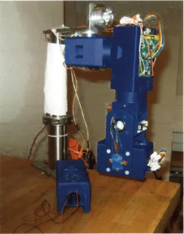
Figure 3-15: Final design
-3.3.2 Electronics Design
In building a modular robot, electronics design is another requirement. Because the module uses brushless motor, we also designed a small H-bridge board for brushless motor. For the motor control, we chose PIC. The communication, we decided to use d by zigbee wireless communication. The zigbee wireless communication has low data rate compared to Bluetooth, another wireless communication, but the data rate is still high to communicate each other between modules. Table 3-5 shows the specification of the zigbee communication. With the communication method and PIC control bards, independent motor module control is possible without wires. Opto-couplers are used to divide H-bridge board. The built boards are shown in Figure 3-15 in the module. Because of zigbee stack processing time, the motor control is performed every 20ms.
3.4 Hand Design
To grip a module, we designed a one degree of freedom hand. The design goal is to achieve compact size and construct an independent module.
Table 3-5. Zigbee specification.
ZigBee
Modulation technique Direct Sequence Spread Spectrum (DSSS)
Protocol stack size 28 kbyte
Battery Not rechargeable (one reason batteries will last for up to 10 years)
Network range: Up to 70m
Typical network join time 30 milliseconds
Maximum network speed: 250 kbit/s
-48-3.4.1 Mechanical Design
To reduce the mass of an actuator, an acme nut and screw are typically used to maximize friction. In this design, we reverse the role of acme nut and screw. Usually, the screw has
Figure 3-16: Hand with acme nut and screw. We reversed the roles of the acme nut and screw.
Force and position sensing Large friction
-.
Inside-spring (or compressive material)
and tactile sensor
Figure 3-17: Hand-pad design.
-large size, but in this design, the nut has similar role as a screw as shown Figure 3-16. We also implemented a finger pad for the purpose of force sensing and compliance as shown in Figure 3-17. By using linear tactile sensor, the robot knows the force applied position and what the magnitude of the force is. Figure 3-18 shows the basic force magnitude and position analyses. If force is applied as shown in Figure 3-19, from the measured value of maximum force and minimum force, the following equation is established:
From the Figure 3-19, we can know that
Max(FA,F, Fc, FD) = F, (3-3)
Min(F, F,, Fc , F) = FD. (3-4)
The applied force is
F= F +F, +Fc + F
=k(4zp + zA B + c) (3-5)
Then, the robot can estimate the position of the force applied, from following equations:
MDV = F(a +x) = FB, 2a + Fc 2a 2a(FB + Fc) x = -a (3-6) F MD = F(a+x) = FA, 2b + FB .2b 2b(FA+ FB) (3-7) y= -b F
From the above equations, the position of he force applied Iculated approximately. The tactile sensor, used in the hand design, does not have a linear force-voltage relationship in all ranges, it makes it difficult to apply the equation. However, the weighted value still gives force sensing and position information.
50-Figure 3-20 shows the hand pad's force sensing value, the moving part, and the stationary part. For the moving part, the pushed position was the center of the finger pad. The calculated x value was 0.1 cm. For the stationary part, the pushed position was the right end of the finger pad. The calculated x value was 2cm and the y value was 0.1 cm approximately. The total length was 4 cm. The result was not exact mostly because of nonlinearity of the tactile sensor. However, the robot can still use the estimated value to know the pushed position approximately. In addition, with this finger pad, we can reduce a shock band width. This finger pad is designed for self - alignment design as shown in Figure 3-9. This finger pad also gives a large friction. Consequently, it can hold a unit with zero motor power as shown in Figure 3-21.
Figure 3-18: Basic model for finger pad force analyses.
I Fc
FD
Figure 3-19: Finger pads for force and applied position analyses
---- V.U OLJUWII -m-0.5 St_Right StLeft St_Up --- 0.5 Mv Down -. 0.3 Mv Left -+- MvUp 1 4 7 10 13 16 19 22 25 28 31 34 37 40 43 46 49 52
Figure 3-20: Hand pad force sensing value
Figure 3-21 .Hand view - can handle one unit without any motor power.
3.4.2 Electronics Design
For the hand module, we selected a small motor with a gear head. Since the friction of the acme nut helps to hold a module during gripping, we can use small power motor with small torque output. Table 3-6 shows the motor specification which is used for hand design. We designed and implemented electronic boards as shown in Figure 3-21. In this module, zigbee wireless communication is also used. We finally built a modular robot arm with the hand and module. The following section shows the control strategy for this modular robot arm.
52 -14A 12 10 8 6 4 2 0
Table 3-6: Actuator specification used in the gripper.
Max cont Permissible Angular Power
output output velocity
Hand 0.15 Nm 0.2 Nm 41 rpm 1.5W
Actuator
-Chapter 4
Module Modeling and Control
SEA limits band-width for force control by virtue of its compliance. Because of its intrinsic compliance, it is desirable for low band-width applications such as human motion. Another strong point of SEA is that the limiting band-width characteristic allows the use of large ratio gear sets, which gives a decoupling effect for each module. For the flexible joint, full state feedback control is proposed [19, 20]. The full state feedback control can be an appropriate application for a robot with known configuration. However, it is not applicable for the SRS, which change shapes. Because of the decoupling effects, each module can be controlled by using a simple PID algorithm. This chapter shows some characteristics of the motor control and introduces the effect of a large gear ratio.
4.1 One Module Modeling and Control: Force
For each module, we performed module modeling and control. For simpler analysis, we assumed the moving range of the module to be small. In addition, we regard other dynamics as a disturbance. Figure 4-1 shows the schematic for this analysis. The environment is modeled as a spring [9]. For simplicity, for small motion, we assumed that
-Figure 4-1: Modeling Each module is
Module
SEA
Load
of the robot arm with three modules. modeled as a spring and mass.
Environment
Figure 4-2: Schematic for module environment interaction.
A load is attached at the end of the gripper and the gripper interacts with the environment. The interaction is expressed as spring and damper.
S Module
KI - Environment stiffness
Distance between Ji - Load inertia
load and center to k - Spring of sensor stiffness motor axis
Figure 4-3: Load side view. At the end of the module, a load is attached. The inertia of moment of the load is J, *
-56-I
I
sin , = ,,
where
g0
is a load side angle.(This approximation is quite applicable for low speed motion shown in the next section.) The one direction contact force is sensed by the SEA force transducer and compensated for the desired force. According to the schematic in Figure 4-2, the following equation was derived:
zgear = (n2J + Jt )S20g + 4ak(Og - 0l)a (4-1)
(k, + mgb)+ J,s2 + 4a2kG, = 4a2kOg . (4-2)
Where, rgear is a gear output torque, n is a gear ratio, 0g is a gear side angle, Jm is a
motor inertia, Jt is a SEA inertia, and a is a distance between the center of SEA and the position spring mounted.
After organizing equation, then we get the following equation:
Tgear = N, ID4. (4-3) Where, N, = J,s2 + 4a2k + k, +mgb = J,s2 + k, + D4= ((n2 + Jt )s2 + 4a2k)N, - (4a2k)2 = (Js 2 + ks)N, - k,2
In the above equations, the following abbreviations are used:
J, = (N2Jm + J,) (4-4)
k = 4a2k (4-5)
k, = k, + mgb (4-6)
-57-Then, it can be found that , = 4ak2 g /D
4 (4-6)
Og= N (D4 g ) . (4-7)
From the above equations, the following equation is derived
OLTF = 4a2kk,(,O -, )
, (4-8) Js 2 + k,
=kg
SJrJi 4 + bJs3 + {(ks + kw)Jr + ksJ,}s2 + b(k, + k)s + kk,k
where, OLTF is an abbreviation for Open Loop Transfer Function. As mentioned in [2], from this equation, the following is inferred:
1. If the wall is very stiff, then the system will oscillate. 2. If the load has negligible inertia, the system will oscillate.
The block diagram in Figure 4-4 illustrates a feedback loop of the given single module system. The input is the desired force and the output is the actual torque. If other modules are attached at the end of the module, then the dynamic behavior of the attached modules will affect the behavior of the modeled module. For example, if two modules are attached together, then there will be two more poles because of the dynamic characteristic of the attached module. With a simple high gain PID control, the system will be unstable. However, the large gear ratio reduces the other un-modeled dynamics by 1/n; therefore, we can use the higher gain than a motor alone. As a result, the SEA is used without considering dynamics of attached modules. However, equation (4-8) shows that if we use high gain, the system becomes unstable. The following arguments show a second order behavior.
The inertia of the motor was 2.25 gcm2, the gear ratio, n, was 231, and the spring stiffness, k was1.6N/mm. a is approximately 2 cm. Therefore, from equation (4-5), we can get