HAL Id: hal-01650737
https://hal.archives-ouvertes.fr/hal-01650737
Submitted on 28 Nov 2017
HAL is a multi-disciplinary open access
archive for the deposit and dissemination of
sci-entific research documents, whether they are
pub-lished or not. The documents may come from
teaching and research institutions in France or
abroad, or from public or private research centers.
L’archive ouverte pluridisciplinaire HAL, est
destinée au dépôt et à la diffusion de documents
scientifiques de niveau recherche, publiés ou non,
émanant des établissements d’enseignement et de
recherche français ou étrangers, des laboratoires
publics ou privés.
Adja Ndeye Sylla, Maxime Louvel, Eric Rutten
To cite this version:
Adja Ndeye Sylla, Maxime Louvel, Eric Rutten. Design Framework for Reliable and Environment
Aware Management of Smart Environment Devices. Journal of Internet Services and Applications,
Springer, 2017. �hal-01650737�
RESEARCH
Design Framework for Reliable and Environment
Aware Management of Smart Environment Devices
Adja Ndeye Sylla
1*, Maxime Louvel
1and Eric Rutten
2Abstract
A smart environment is equipped with numerous devices (i.e., sensors, actuators) that are possibly distributed over different locations (e.g., rooms of a smart building). These devices are automatically controlled to achieve different objectives related, for instance, to comfort, security and energy savings. Controlling smart
environment devices is not an easy task. This is due to: the heterogeneity of devices, the inconsistencies that can result from communication errors or devices failure, and the conflicting decisions including those caused by environment dependencies. This paper proposes a design framework for the reliable and environment aware management of smart environment devices. The framework is based on the combination of the rule based middleware LINC and the automata based language Heptagon/BZR (H/BZR). It consists of: an abstraction layer for the heterogeneity of devices, a transactional execution mechanism to avoid inconsistencies and a controller that, based on a generic model of the environment, makes appropriate decisions and avoids conflicts. A case study with concrete devices, in the field of building automation, is presented to illustrate the framework. Keywords: Smart Environments; Reliability; Transactional Middleware; Automata language
1 Introduction
Smart environments are equipped with numerous de-vices that are automatically controlled to achieve different objectives. For instance, a window can be opened to cool or ventilate a room. Controlling smart environments devices raises several problems. First, devices are built by different manufacturers and use heterogeneous communication technologies. Second, a device may become unreachable due to a hardware fail-ure or a communication error. In this case, a command sent to this device is not received and the correspond-ing action is not performed. Assumcorrespond-ing that the action has been performed leads to a runtime inconsistency (inconsistency in the rest of the paper). For instance, sending the command close to a door and assuming that it is closed becomes an inconsistency if the door remains opened due to a communication error or a failure. Third, the decisions taken to achieve the ob-jectives may be conflicting or violate other obob-jectives. Conflicts and violations are either explicit or implicit. Implicit conflicts and violations are due to environ-ment dependencies and are not easy to detect. For in-stance, opening a window to cool a room can raise the
noise level (resp. the CO2concentration). This can
vio-*Correspondence:[email protected]
1Univ. Grenoble Alpes, CEA, LETI, DACLE, LIALP, F-38000 Grenoble
Full list of author information is available at the end of the article
late an objective that limits the room noise level (resp.
the CO2 concentration) at a given threshold.
In the literature, several solutions have been
pro-posed for the reliability of smart environments [1,2,3,
4,5,6,7,8,9,10,11,12,13,14,15,16]. These solutions use different methods (e.g., model checking, pairwise comparison of rules) to prevent from explicit and/or implicit conflicts and objectives violations. However, using these solutions requires to manually program or model the behaviour of the smart environment. Then, the program or the model is verified to detected spe-cific errors (e.g. conflicts). If an error is detected, the program or the model is manually modified and veri-fied again. This can be tedious because developers have to consider all the combinatorial possible cases. More-over, these solutions do not handle the inconsistencies due to communication errors and hardware failures.
This paper proposes a design framework for reliable and environment aware management of smart environ-ment devices. The proposed framework allows for
• Declarative management of devices, by specifying the target objectives and not how to reach them; • Avoidance of both explicit and implicit conflicts; • Avoidance of inconsistencies that are caused by
communication errors and hardware failures. The framework is based on the combination of a
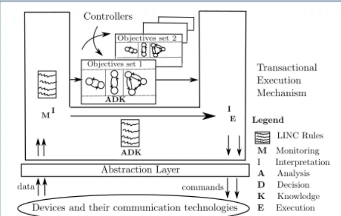
Transactional Execution Mechanism
Abstraction Layer
Devices and their communication technologies
data commands Controller ADK M IE ADK I Objectives Legend M Monitoring I Interpretation A Analysis D Decision K Knowledge E Execution LINC Rules
Figure 1 Devices management through the framework
a reactive language (Heptagon/BZR [18]). As shown
in Figure 1, the proposed framework enables the
au-tonomic management of devices through a variant of
the MAPE-K loop [19] called MIADIE-K
(Monitor-ing, Interpretation, Analysis, Decision, Interpretation, Execution and Knowledge) and consists of:
• An abstraction layer: To deal with the hetero-geneity of smart environment devices;
• A transactional execution mechanism: To prevent from the occurrence of inconsistencies; • An environment aware controller: To make
appropriate decisions and prevent from both ex-plicit and imex-plicit conflicts. The controller re-lies on a generic model of the environment. The generic aspect of this model allows to use the same controller for other environments that have the same types of devices (e.g., rooms of a building). To improve environment monitoring, the proposed framework allows developers to design monitoring rules, in LINC, and create soft sensors from physi-cal sensors. A soft sensor aggregates or transforms the data of one or more physical sensors. The framework also allows developers to design rules that perform ac-tions on the environment assuming that these rules do not interact with potential conflicting devices (which must be handled by the environment aware controller).
The paper is structured as follows. Section 2 gives
the background material. Then, Section 3 describes
the proposed framework. Section 4 presents how
de-vices are managed using the framework. Section 5
il-lustrates the framework through a case study, with concrete devices, in the field of building automation.
Section6discusses related work. Finally, Section7
con-cludes the paper and presents the future works.
2 Background
The proposed framework relies on a transactional middleware and a reactive language that supports
the synthesis of controllers. The transactional mid-dleware enables the communication with devices and avoids inconsistencies. The reactive language enables the declarative management of devices while prevent-ing from conflicts and objectives violations. In this
pa-per, the transactional middleware LINC [17] and the
reactive language Heptagon/BZR [18] are used.
2.1 LINC middleware
LINC [17] is a rule based middleware used to develop
and deploy distributed applications. It has been used
in several domains such as building automation [20,
21,22] and wireless sensor networks [23, 24,25].
2.1.1 LINC concepts
LINC relies on three paradigms:
• Associative Memory [26]: It is implemented as
a set of distributed tuple spaces containing re-sources (tuples of strings). In LINC, tuple spaces are called bags. They are grouped, according to the application logic, in objects. Resources are used to model the entities of an application and are manipulated using three operations: rd, get and put. The rd is used to verify the presence of a resource in a bag. The get is used to remove a resource and the put is used to insert a resource. These operations are used in production rules.
• Production Rules [27]: A production rule
con-sists of two parts: a precondition and a
perfor-mance. In the precondition, the operation rd is
used, with a partially instantiated resource as pa-rameter, to verify specific conditions in the sys-tem (e.g., presence detected). If these conditions are true, the performance is triggered. The perfor-mance uses the three operations. The rd is used to verify conditions. The get and the put are used to perform actions on the system and update its logical state (i.e., resources stored in LINC bags).
• Distributed Transactions [28]: They are used
in the performance part of a rule. A transaction allows to group as one operation the verification of conditions (rd), the realisation of actions (put), and the update of the system logical state (get,
put). Thus, the performance part of a rule may
abort if, for instance, the verification of a con-dition through a rd operation is no longer true. The performance part also aborts if a put opera-tion fails because the corresponding acopera-tion (e.g., switch on a lamp) cannot be performed (e.g., due to a communication error or a hardware failure).
2.1.2 LINC in the context of smart environments
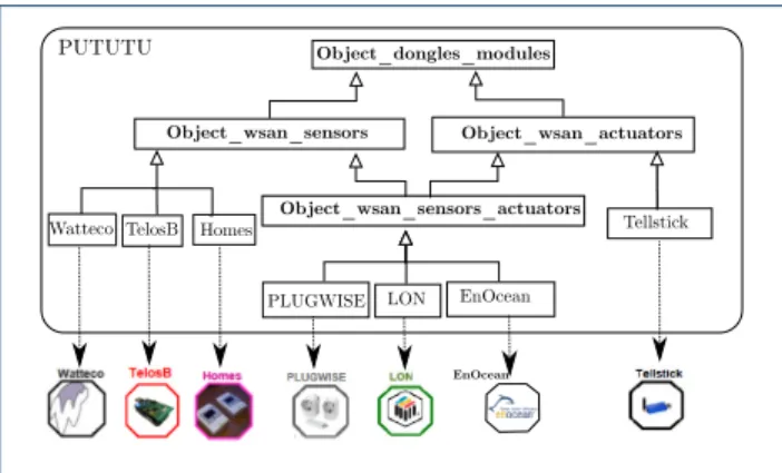
LINC provides a framework called PUTUTU [20,21]
PUTUTU
EnOcean
Object_dongles_modules
Object_wsan_sensors Object_wsan_actuators
Object_wsan_sensors_actuators
Watteco TelosB Homes
PLUGWISE LON EnOcean
Tellstick
Figure 2 PUTUTU framework
hides their heterogeneity. PUTUTU consists of
sev-eral LINC objects. As shown in Figure2, these objects
encapsulate different technologies (e.g., TelosB, LON, Tellstick) and inherit from four generic objects:
• Object_dongles_modules: It is used to man-age a dongle or any other equipment plugged in an ethernet or a USB port. The dongle allows to communicate with the devices of a specific tech-nology. It has two bags: Type and Location. Type associates the id of a device to its type. Location associates the id of a device to its location. • Object_wsan_sensors: It is used to manage
sensors. It has one additional bag called Sensors which associates the id of a sensor to its latest measured value, in the format (id, value). • Object_wsan_actuators: It is used to manage
actuators. It has one additional bag called
Actua-tors which is used to send commands to the
actu-ators. The resources of this bag are in the format
(id, command, parameters). The insertion of such
a resource, using the operation put, actually sends the command to the specified actuator.
• Object_wsan_sensors_actuators: It is used to manage technologies providing both sensors and actuators (e.g. EnOcean). This object is de-rived from the two previous generic objects and inherits from their bags (e.g., Sensors, Actuators).
2.1.3 LINC rule example
Listing 1 presents an example of a LINC rule that
switches on the lamp of a room when a presence is detected. This room is equipped with a TelosB pres-ence sensor and an EnOcean lamp actuator.
This rule consists of two parts: a precondition (before the symbol ::) and a performance (after the symbol ::). The precondition consists of a rd on the bag States containing the logical state off and a rd on the bag Sensors of the TelosB object to detect a presence. When the lamp is off, the rule waits for a resource
indicating a presence in the room. This triggers the performance. The performance consists of two trans-actions (between {}). The first transaction verifies if
the presence is still detected (line 5), sends the
com-mand to the lamp (line6) and updates its logical state
(lines 7and 8). LINC ensures that all the actions are
done or none of them. Hence, if the put operation fails on the actuator (e.g., communication error, actuator failure), the lamp stays off in the bag States.
If no error occurs in the first transaction, the second
transaction will fail at line 12 (the lamp is now on).
If the presence is not detected anymore, both
trans-actions will fail (lines 5 and 11). Finally, if the lamp
cannot be switched on (e.g., due to a communication error), the second transaction will send a SMS to the maintenance team to inform them of the problem.
Executing this rule in another room simply re-quires replacing the PUTUTU objects (i.e., TelosB and EnOcean) and the ids (i.e., t_pr_1, e_l_1), re-spectively, by the communication technologies and the ids of the room presence sensor and lamp actuator.
1 [ " B u i l d i n g " , " S t a t e s " ] . r d ( " e _ l _ 1 " , " o f f " ) & [ " T e l o s B " , " S e n s o r s " ] . r d ( " t _ p r _ 1 " , " T r u e " ) 3 : : { 5 [ " T e l o s B " , " S e n s o r s " ] . r d ( " t _ p r _ 1 " , " T r u e " ) ; [ " EnOcean" , " A c t u a t o r s " ] . p u t ( " e _ l _ 1 " , " o n " ) ; 7 [ " B u i l d i n g " , " S t a t e s " ] . g e t ( " e _ l _ 1 " , " o f f " ) ; [ " B u i l d i n g " , " S t a t e s " ] . p u t ( " e _ l _ 1 " , " o n " ) ; 9 } { 11 [ " T e l o s B " , " S e n s o r s " ] . r d ( " t _ p r _ 1 " , " T r u e " ) ; [ " B u i l d i n g " , " S t a t e s " ] . r d ( " e _ l _ 1 " , " o f f " ) ; 13 [ " B u i l d i n g " , " Sms" ] . p u t ( " XX" , " l a m p p r o b l e m " ) ; } .
Listing 1 LINC rule example
2.2 Heptagon/BZR language
Heptagon/BZR or H/BZR [18] is a language used to
build reactive systems, by means of automata and equations. It enables model checking to verify prop-erties (e.g., absence of objectives violations) and espe-cially the synthesis of controllers to enforce properties.
2.2.1 Design of a H/BZR program
A H/BZR program is designed as a set of blocks called nodes. A node has input flows and output flows. It contains equations defining output flows in terms of input flows, local variables, and possibly intermediate states variables. These equations can be encapsulated in states of automata. They can also instantiate other nodes. Each node can be provided with a contract that defines a set of properties to be enforced on the pro-gram. These properties are enforced, at compilation
On O not c1 c2 cmd = s_on nothing lum = 500 cmd = s_o nothing lum = 0 Lamp(c1, c2) = cmd, lum
Figure 3 Example of H/BZR node
Automaton consists of states, one of them being the initial state, and transitions between them. States are associated to equations that give specific values to the output flows of the automaton node. The value of an output flow must be defined at each instant. Transi-tions are associated to boolean expressions related to one or several input flows of the automaton node.
Figure 3 presents an automaton modelling a lamp.
This automaton is contained in a node that has two input flows (c1, c2) and two output flows (cmd, lum). The automaton has two states (Off, On) and two transitions. Each state is associated to two equations that give values to the output flows. The equation cmd = s_off → nothing means that at the state Off, cmd is equal to s_off (switch off) if this state is newly activated and nothing otherwise. The rea-son is twofold. First, the value of an output flow must be defined at each instant. Second, this prevents from continuously computing cmd = s_off while the lamp is already off. The equation lum = 0 means that at the state Off the lamp provides a luminosity equal to 0 lux. The input flows c1 and c2 are boolean variables. The initial state of the lamp automaton is Off. In this state, when c1 is false (i.e., not c1 is true), the automaton goes to the state On and the output flows take the values given by the equations of this state. Otherwise (i.e., c1 is true), the automaton remains in the state Off. This means that in the state Off, there is an implicit transition associated to c1 that allows to remain in this state. In the same way, when the automaton is in the state On, if c2 is true, the automaton goes to Off. Otherwise (i.e., c2 is false) it remains in the state On. There is an implicit transition associated to not c2 allowing to stay in the state On. This node example could be designed using only one input flow to reduce the number of variables used. For instance, not c1 and c2, in the automaton transitions, could be respectively replaced with not c and c.
Discrete controller synthesis (DCS) [18] a formal method used to enforce a set of properties, called ob-jectives, on a model. DCS is enabled by H/BZR at compilation time. Given a model that represents all the possible behaviours of a system and a set of target
objectives, DCS inhibits all the behaviours that violate the objectives. To do this, DCS requires to partition the variables of the considered model in two sets: con-trollable and unconcon-trollable variables. Once the vari-ables are partitioned, the DCS algorithm explores the state space of the model and computes the possible values of the controllable variables. The aim is to en-force the target objectives, whatever the values of the uncontrollable variables. For instance, c1 and c2 in
Figure3can be defined as controllable variables to
en-force an objective related to the luminosity of a room. After the controller synthesis, several solutions can be possible regarding the objectives to achieve. For instance, the lamp can be Off or On to provide a lumi-nosity greater or equal to 0 lux. However, one solution must be chosen. For this, the backend of the H/BZR compiler selects one of the solutions. It is possible to guide the selection with two options. Firstly, the com-piler backend favours the value true to the value false for a boolean variable. For instance, in the lamp
au-tomaton (Figure3), to favour staying Off, the
transi-tion from Off to On is associated to not c1. Here, the implicit transition that remains in the state Off (as-sociated to c1) is favoured by the compiler backend.
The second option is that the compiler backend fol-lows the declaration order of the variables and gives to them the value true. If this does not enforce the target objectives it changes the values to false following the inverse of the declaration order. Hence, when declar-ing c1 before c2, if two transitions T1 and T2 respec-tively associated to not c1 and not c2 are possible, the compiler backend will choose T2. It gives true to c1 and false to c2 (not c2 is true and T2 is chosen).
2.2.2 Execution of a H/BZR program
The compilation of a H/BZR program generates a code in C or Java. In both cases, the generated code includes a function called step. The step takes as parameter a set of input values, computes the output values that allow to reach the target objectives, and updates the state of the automaton that models the system. One execution of the step function corresponds to one re-action of the system. Therefore, the step must be ex-ecuted each time a reaction is required. Executing the step requires to ensure that the state of the automa-ton is always consistent with the state of the actual system. This is done by combining LINC and H/BZR. 2.3 Combination of LINC and H/BZR
LINC is designed to implement rules that react to events (e.g., production of a new sensor value). Hence, a LINC rule is used to execute the step function when necessary (i.e., each time an event occurs). This rule first collects data (e.g., through sensors) and then, it
invokes the step in order to compute appropriate com-mands to send to the system (e.g., through actuators). Thanks to its transactional guarantees, LINC ensures that a group of actions are all done or none of them is done. The step is thus executed in a transaction, to-gether with the sending of the commands. Hence, if a command cannot be sent, the step is not executed and the state of the automaton stays consistent with the state of the actual system. More details on the
combi-nation of LINC and H/BZR can be found in [29].
2.4 Autonomic computing
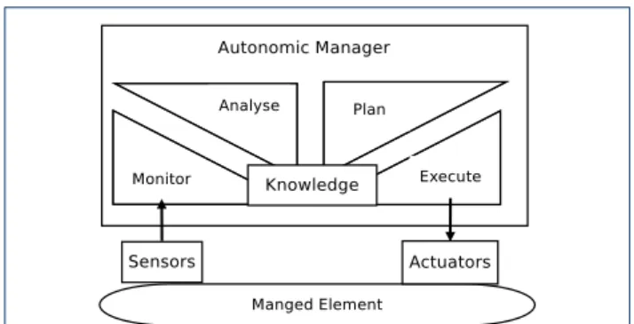
Autonomic computing [19] has been used in
sev-eral solutions for the management of smart
environ-ment devices [30, 31, 32, 33]. It consists in creating
systems that manage themselves by performing configuration, optimisation, healing or self-protection. This is done for instance through a
MAPE-K loop. In an autonomic system (cf. Figure4), an
au-tonomic manager, based on knowledge, continuously
1 monitors a managed element by collecting data;
2 analyses the data to decide if changes are needed;
3 plans changes based on the analysed data;
4 executes the changes through actuators.
Figure 4 Autonomic System Architecture
The knowledge consists of information related to the managed element and to its environment. The knowl-edge is updated when executing the changes.
3 Framework description
As depicted in Figure 1, the framework consists of:
• An abstraction layer: It is based on the as-sociative memory of the middleware LINC. The operations rd and put are used to respectively read the latest value measured by any sensor (i.e., rd(sensor_id,val)) and to send a command to any actuator (i.e., put(actuator_id,command)). • An environment aware controller: It is de-signed through H/BZR and DCS. The controller computes appropriate commands, to reach the ob-jectives without conflict, and is based on a generic
model of the environment. This model describes the behaviour of the devices and captures envi-ronment dependencies. The model is generic in the sense that it does not describe the behaviour of specific devices (e.g., lamp_12) but types of de-vices (e.g., lamp). This allows to use the same con-troller for other environments that have the same types of devices. For instance, let us consider a controller designed for a room equipped with one lamp and one shutter. This controller can be in-stantiated in other rooms equipped with a lamp and a shutter with any communication technol-ogy. This controller can also be instantiated in an open-space equipped with several lamps and several shutters, all the lamps (resp. shutters) are seen as one lamp (resp. one shutter) by the con-troller. Finally, the controller can be reconfigured, under some conditions, to deal with changing ob-jectives (e.g., weekdays vs. weekends).
• A transactional execution mechanism: It is based on the distributed transactions of the mid-dleware LINC. The update of the controller state and the update of the actual system is included in the same transaction. Hence if an action cannot be performed on the actual system (e.g., due to a communication error), the controller state is not updated. Hence, the inconsistencies between the controller and the actual system are avoided. 3.1 Autonomic management of devices
The proposed framework enables the autonomic man-agement of smart environment devices, through a vari-ant of the MAPE-K loop (MIADIE-K loop). As shown
in Figure 1, the devices are monitored and the
col-lected data are interpreted (MI). Then, an analysis is done and appropriate commands are computed (AD), based on knowledge (K). Finally, the commands are in-terpreted and sent and the knowledge is updated (IE). • Monitoring and Interpretation (MI): Pro-vide the data required to make decisions. Sensor data are first collected through the abstraction layer. Then, the data may be interpreted. The aim is to aggregate them, to transform them or to use them to estimate other data. For instance if a temperature data is needed and there are two temperature sensors, their average may be used as the temperature. Another example is to use the
value measured by a CO2 sensor to estimate the
number of people. Data transformation, aggrega-tion and estimaaggrega-tion are not subject to conflicts (they do not involve actuators) and thus, are per-formed by writing LINC rules, by the developers. • Analysis and Decision (AD): Analyse the data obtained from the monitoring and compute the
commands to send to the actuators. To avoid conflicts, the commands are computed by a con-troller (step function) obtained through H/BZR and DCS. Nevertheless, it is possible for devel-opers to manually write rules to achieve simple objectives (involving devices that do not affect an
environment parameter for instance CO2). Such
objectives are easy to achieve while avoiding con-flicts and thus, do not require to use the controller. These rules also analyse specific monitoring data and compute commands, based on knowledge. • Knowledge (K): The knowledge used by the
controller is one instance of the generic environ-ment model. It consists of a set of automata and equations. Each automaton describes the be-haviour of a specific device by specifying its states, its transitions and its effects on the environment. The knowledge used by the LINC rules (achieving simple objectives) is a set of resources stored in bags and modelling the states of specific devices. • Interpretation and Execution (IE): Interpret the computed commands, send them and update the knowledge. The interpretation allows to send a specific command to several actuators.
4 Framework usage by developers
The proposed framework allows developers to• Generate an executable model from a model of the environment and a set of target objectives; • Create soft sensors and soft actuators
re-spectively from physical sensors and actuators; • Deal with changing objectives through the
automatic reconfiguration of the controller; • Consider a high number of devices through
the modular design of the MIADIE-K loop; • Write LINC rules to manually achieve simple
objectives, involving a small number of devices, that do not lead to conflicts.
4.1 Generating an executable model
Developers design a H/BZR program by defining a model of the considered environment, the target objec-tives and the controllable variables. Then, the frame-work generates an executable model that manages the devices of the environment and achieves the objectives.
4.1.1 Modelling the environment
Developers first consider a set of parameters of the environment and identify all the devices that affect at least one parameter. Then, developers model each type of identified device as an automaton contained in a H/BZR node. The automaton modelling a device type specifies the different states of the device type, its state transitions, the environment parameters it affects and
Shutter(c, o_lum) = cmd, lum, air
Closed Opened not c not c cmd = close nothing lum = 0 air = false cmd = open nothing lum = o_lum air = true
(a) Shutter node
On O not c1 c2 cmd = s_on nothing lum = 500 cmd = s_o nothing lum = 0 Lamp(c1, c2) = cmd, lum (b) Lamp node contract enforce
with (c1_lamp, c2_lamp,c_shutter)
i_presence lum in [500,600]
Room(i_presence, o_lum) = shutter_cmd, lamp_cmd
(lamp_cmd, lum_lamp) = Lamp(c1_lamp, c2_lamp); (shutter_cmd, lum_shutter, air) = Shutter(c_shutter, o_lum); lum = lum_lamp + lum_shutter;
(c) H/BZR contract
Figure 5 H/BZR program of the room example
how it affects them. Modelling types of devices, instead of specific devices, allows for the models re-usability.
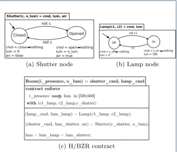
Let us consider as an example, in the context of building automation, a room equipped with a shut-ter and a lamp. To model this room, two parameshut-ters (luminosity and air) are first considered. Then, two automata are designed to model a shutter and a lamp.
Figure 5a presents the automaton that models a
shutter. This automaton is contained in a H/BZR node that has two input flows (c, o_lum) and three output flows (cmd, lum, air). The automaton has two states (Closed, Opened) and two transitions. Each state is as-sociated to three equations to produce the command of the shutter (cmd) and specify its effects on the envi-ronment (lum, air). In the state Closed, the command is equal to close (resp. nothing) if this state is (resp. not) newly activated. This prevents from continuously computing the command close while the shutter is already Closed. In this state, the shutter provides a luminosity equal to zero (lum = 0) and does not allow outdoor air to pass (air = false). In the state Opened, the shutter provides a luminosity equal to the outdoor luminosity (lum = o_lum) and allows outdoor air to pass (air = true). The transitions going from a given state to a different one are associated to not c. This allows to open or close the shutter only when necessary.
Figure5bpresents the lamp automaton. This
automa-ton is the same than the one presented in Figure 3.
4.1.2 Defining the target objectives and the controllable variables
Developers design a main H/BZR node that instan-tiates the automata modelling the devices and has a contract part. Then, developers define in the contract, the target objectives and the controllable variables.
Defining the objectives Developers specify the val-ues that the considered environment parameters must take. These values may depend on data collected from the environment. This is done using variables and op-erators. Variables are used to refer to the collected data and also to the environment parameters. Opera-tors, for instance, ⇒ (logical implication) and ∧ (and) are used to express the relations between the variables. Examples of objectives for a room are:
1 presence ⇒ luminosity in [500,600] lux;
2 presence ⇒ noise < 80 dB;
3 presence ∧ temperature < 17◦C ⇒ heat;
4 presence ∧ CO2 > 800 ppm ⇒ ventilation.
The first objective means that if a presence is detected, in the room, the luminosity must be between 500 and 600 lux. The second objective means that if a pres-ence is detected, the noise level must be lower than 80 dB. The third objective (resp. the fourth objective) means that if a presence is detected and the
tempera-ture is below 17◦C (resp. the CO2is above 800 ppm),
the room must be heated (resp. ventilated). The de-vices required to reach the objectives and the actions to perform on them will be decided by the step func-tion. For instance, the first objective can be reached by switching on the lamp or opening the shutter. The second action may be preferred for energy savings.
Defining the controllable variables Developers first analyse the input flows of the nodes that contain the automata modelling the devices. The aim is to identify the input flows that are controllable (their values are not given by the monitoring). Then, developers declare the identified input flows, in the contract part of the main H/BZR node, as controllable variables. For
in-stance, in the lamp automaton, presented in figure5b,
the input flows c1 and c2 are controllable variables.
In the shutter automaton, presented in Figure 5a, the
input flow c is a controllable variable. The input flow o_lum represents the value measured by an outdoor luminosity sensor and hence it is uncontrollable.
Developers can use the declaration order of the con-trollable variables to express preference between the transitions of the different automata. A transition T1 associated not c1 is preferred to another transition T2 associated to not c2 if is c1 is declared after c2.
4.1.3 Example of H/BZR program for a room
Let us consider again the room, equipped with a shut-ter and a lamp. The objective to achieve is to maintain the luminosity between 500 and 600 lux when a pres-ence is detected while minimising the energy consump-tion (i.e., prefer natural lighting to artificial lighting). The H/BZR program defined for this room is
pre-sented in Figure 5. It consists of three nodes. The
Generic Environment Model Objectives and controllable variables
H/BZR Compiler Rule Template Generator PUTUTU Framework LINC Objects Step Function
with controllable variables enforce objectives Design Time 1 2 contract Runtime LINC Rule Template presence: t_pr_1: TelosB: indoor
co2: co2_543: TelosB: indoor lamp: lamp_69: TellStick: indoor ...
type: id: technology: indoor
Information File
LINC Rule Instance 3 Rule Instance
Generator
IsInstanceOf
Figure 6 Executable model generation
first two nodes respectively contain the shutter and
the lamp automata (Figures 5a and 5b). The third
node, presented in Figure 5c, is the main node. It
has two input flows (i_presence and o_lum) and two output flows (shutter_cmd and lamp_cmd). The input flows respectively represent the values measured by the room indoor presence sensor and outdoor luminosity sensor. The output flows respectively correspond to the commands to send to the shutter and to the lamp. This node defines a contract to enforce the target objective, through DCS, with the controllable vari-ables c1_lamp, c2_lamp and c_shutter. These con-trollable variables are respectively related to the lamp and the shutter. The luminosity objective is expressed as follows: i_presence ⇒ lum in [500,600] where lum is equal to the sum of the luminosity provided by the shutter and the lamp. The controllable of the shut-ter is declared afshut-ter those of the lamp to specify that natural lighting is preferred to artificial lighting.
4.1.4 Executable model generation
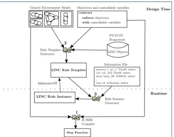
Figure 6 shows how from the generic environment
model, the target objectives and the controllable vari-ables (i.e., a H/BZR program designed by developers) are generated the following elements:
1 A step function;
2 A LINC rule template;
3 An instance of the LINC rule template.
At runtime, the LINC rule instance invokes the step function each time a relevant event occurs. When in-voked, the step computes and returns appropriate commands that will be executed by the rule instance.
Step generation The step is generated through the compilation of the H/BZR program designed by
de-velopers. For instance, the compilation of the H/BZR
program presented in Figure 5generates a step.
LINC execution rule template generation The execu-tion rule template is generated from the H/BZR pro-gram and the objects of the PUTUTU framework. This rule template collects the inputs of the main H/BZR node, invokes the step function with the collected in-puts and sends the computed commands (outin-puts of the main H/BZR node). The precondition of the rule template consists of a set of rd operations: one rd for each input of the main H/BZR node and one rd to in-voke the step. The performance of the rule template consists of a sequence of two transactions. The first transaction consists of a set of rd operations to verify if the collected inputs have not changed and a set of
put operations to send the computed commands and
update the knowledge. One put is generated for each output of the main H/BZR node and one put is gener-ated to update the knowledge. The second transaction consists of a set of rd operations to verify if the col-lected inputs did not change, one rd to verify if the knowledge did not change and one put operation to signal an actuator problem to the maintenance team. In the second transaction, the fact that the collected inputs are still the same and the knowledge did not change means that the first transaction aborted when performing an action on an actuator (it is faulty or unreachable). Otherwise, the knowledge would be up-dated. Hence, the maintenance is informed if the in-puts are the same and the knowledge did not change.
Listing 2presents the rule template generated from
the H/BZR program presented in Figure 5. The
precondition of this rule first reads the value mea-sured by an indoor presence sensor in the variable i_pres_id_val. This is done by applying a rd on the
Sensors bag of a PUTUTU object. Then, at line2, the precondition reads the value measured by an outdoor luminosity sensor in the variable o_lum_id_val. At
line 3, the precondition stores the read sensor values
in one variable called inputs using the LINC opera-tion IC (i.e., INLINE_COMPUTE ). In LINC, the IC operation executes any python code and returns a tu-ple of string (here containing only one value). Finally,
the precondition invokes the step function (line 4)
and stores the computed commands in the variables
shutter_cmd and lamp_cmd (line 5). These variables
will be used in the first transaction of the performance. The first transaction verifies if the sensors data did
not change (lines 8, 9). Then, it sends the computed
shutter command to a shutter actuator. This is done by applying a put on the Actuators bag of a PUTUTU object. This transaction also sends the computed lamp
command to a lamp actuator (line11) and updates the
1 [ O b j e c t n a m e , " S e n s o r s " ] . r d ( i d , i _ p r e s _ i d _ v a l ) & [ O b j e c t n a m e , " S e n s o r s " ] . r d ( i d , o _ l u m _ i d _ v a l ) & 3 I C : i n p u t s =" (%s ,%s ) " %(i _ p r e s _ i d _ v a l , o _ l u m _ i d _ v a l ) & [ " HBZR" , " S t e p " ] . r d ( i n p u t s , c u r _ s t a t e , commands) & 5 I C : s h u t t e r _ c m d , lamp_cmd = e v a l ( commands) : : 7 { [ O b j e c t n a m e , " S e n s o r s " ] . r d ( i d , i _ p r e s _ i d _ v a l ) ; 9 [ O b j e c t n a m e , " S e n s o r s " ] . r d ( i d , o _ l u m _ i d _ v a l ) ; [ O b j e c t n a m e , " A c t u a t o r s " ] . p u t ( i d , s h u t t e r _ c m d ) ; 11 [ O b j e c t n a m e , " A c t u a t o r s " ] . p u t ( i d , lamp_cmd) ; [ " HBZR" , " S t e p " ] . p u t ( i n p u t s , c u r _ s t a t e , " " ) ; 13 } { 15 # o t h e r o p e r a t i o n s t o s i g n a l a p r o b l e m } .
Listing 2 Generated execution rule template example
knowledge (line12). If a command cannot be sent due
to a problem on the shutter (resp. the lamp) actuator,
the put at line10(resp. line11) fails and the knowledge
is not updated. This prevents from inconsistencies. To signal the shutter or the lamp problem, the second transaction, sends a SMS to the maintenance team.
LINC execution rule instance generation From the generated rule template, a rule instance is generated with the actual sensors and actuators. This is done using a file that contains information related to the considered environment devices (i.e., type, id, technol-ogy, location). To generate an instance of the execution rule template, the rule instance generator replaces:
• In rd operation, Objectname and id by the tech-nology and the id of the corresponding sensor; • In put operation, Objectname and id by the
tech-nology and the id of the corresponding actuator.
Listing3 presents the file that describes the devices
of the room example. This file specifies that the room is equipped with a TelosB indoor presence sensor with an id equal to pr1, a RFXCOM outdoor luminosity sensor, an EnOcean lamp actuator and a KNX shutter actuator.
1 # t y p e : i d : t e c h n o l o g y : l o c a t i o n p r e s e n c e : p r 1 : T e l o s B : i n d o o r 3 l u m i n o s i t y : l u 9 : RFXCOM: o u t d o o r l a m p : e _ l _ 1 : EnOcean: i n d o o r 5 s h u t t e r : s h u t t e r _ 4 3 : KNX: i n d o o r
Listing 3 Information file example
Listing 4 presents the rule instance generated from
the execution rule template of Listing 2 and the
de-scription file presented in Listing3. This rule reads the
values of specific sensors, invokes the step and sends the computed commands to specific actuators.
1 [ " T e l o s B " , " S e n s o r s " ] . r d ( " p r 1 " , i _ p r e s _ p r 1 _ v a l ) & [ " RFXCOM" , " S e n s o r s " ] . r d ( " l u 9 " , o _ l u m _ l u 9 _ v a l ) & 3 I C : i n p u t s =" (%s ,%s ) " %(i _ p r e s _ p r 1 _ v a l , o _ l u m _ l u 9 _ v a l ) & [ " HBZR" , " S t e p " ] . r d ( i n p u t s , c u r _ s t a t e , commands) & 5 I C : s h u t t e r _ c m d , lamp_cmd = e v a l ( commands) : : 7 { [ " T e l o s B " , " S e n s o r s " ] . r d ( " p r 1 " , i _ p r e s _ p r 1 _ v a l ) ; 9 [ " RFXCOM" , " S e n s o r s " ] . r d ( " l u 9 " , o _ l u m _ l u 9 _ v a l ) ; [ " KNX" , " A c t u a t o r s " ] . p u t ( " s h u t t e r _ 4 3 " , s h u t t e r _ c m d ) ; 11 [ " EnOcean" , " A c t u a t o r s " ] . p u t ( " e _ l _ 1 " , lamp_cmd) ; [ " HBZR" , " S t e p " ] . p u t ( i n p u t s , c u r _ s t a t e , " " ) ; 13 } { 15 # o t h e r o p e r a t i o n s t o s i g n a l a p r o b l e m } .
Listing 4 Generated execution rule instance example
1 [ O b j e c t n a m e , " S e n s o r s " ] . r d ( i d , c o 2 _ i d _ v a l ) & COMPUTE: p r e s _ v a l = p r e s _ f r o m _ c o 2 ( c o 2 _ i d _ v a l ) 3 : :
{
5 [ " S o f t S e n s o r s " , " S e n s o r s " ] . p u t ( p r e s _ i d , p r e s _ v a l ) ; } .
Listing 5 Monitoring rule template example
4.2 Creating soft sensors
Developers can create soft sensors from physical sen-sors to aggregate the data collected from the environ-ment, to transform them or to estimate other data. For that, they write specific LINC rules called monitoring rules. These rules do not involve actuators and cannot be conflicting. These rules rely on the abstraction layer which hides the devices heterogeneity. Developers can also write monitoring rules for other data sources (e.g., agenda) to transform data or estimate required data.
Listing 5 presents an example of monitoring rule
template. This rule template creates a soft presence
sensor from a physical CO2 sensor. The precondition
of this rule first reads in the variable co2_id_val, the
value measured by a CO2 sensor. Then, the
precon-dition invokes a function (i.e., pres_from_co2) with the variable co2_id_val as parameter to estimate if a presence is detected or not. The result is stored in the variable pres_val. The performance inserts the resource (pres_id, pres_val) in the Sensors bag of the SoftSensors LINC object. This specifies that a presence has been detected or not by the soft pres-ence sensor with the id pres_id. This monitoring rule
is triggered each time a new CO2value is produced.
Once designed, a monitoring rule template is instan-tiated for a specific environment and the created soft sensor is added in this environment information file. Soft sensors and physical sensors are handled similarly when instantiating the step execution rule template.
4.3 Creating soft actuators
Developers can create soft actuators to allow some computed commands to be sent to more than one ac-tuator. A soft actuator groups several actuators, that have different ids and possibly different communica-tion technologies, as one actuator. When creating a soft actuator, developers specify the number of actu-ators that must perform the action corresponding to the command (e.g., three lamps must be switched on). When used in a rule, a soft actuator is seen as any other actuator: a put is done on its Actuators bag. When applied, the put sends the specified command to all the physical actuators that are associated to the soft actuator. The put succeeds if the action corresponding to the command can be performed by the specified number of actuators. Otherwise, the put fails.
Creating a soft actuator consists first in creating a specific PUTUTU object that encapsulates one or sev-eral technologies. This is straightforward and is done by inheriting from the existing PUTUTU objects that encapsulate the technologies of the target physical ac-tuators. By default, the operation put(id,command) on a PUTUTU object Actuators bag sends the command, given as parameter, to only one actuator. Therefore, it is required to modify the behaviour of the put opera-tion, on the created object Actuators bag, to send the command to the required number of actuators.
Once defined, a soft actuator is added in the envi-ronment information file and will be used by the rule that invokes the step, as if it were a physical actuator. 4.4 Dealing with changing objectives
Controlling smart environment devices requires to deal with changing objectives. The reason is that a realis-tic environment can have different configurations with different objectives (e.g., working time and holidays in a building). This is done by first designing a controller for each configuration. Then, switching between the
controllers, at runtime, as illustrated in Figure7.
Let us consider a system and a set of controllers, de-signed in H/BZR, to achieve different objectives. To achieve its objectives, each controller accepts specific states of the system and rejects the other states (i.e., those that can violate its objectives). A state rejected by a given controller is not allowed to be reached when this controller is activated. Hence, switching an
acti-vated controller (e.g., Ct1) for another controller (e.g.,
Ct2) is possible only if the current state of the system
(accepted by Ct1) is accepted by the controller Ct2.
Switching controllers is not an easy task in general because it is not straightforward to decide if a given state is accepted by a controller. Indeed, a state is accepted by a controller if it:
• Belongs to the state space (set of known states) of the controller;
Transactional Execution Mechanism Controllers
Abstraction Layer
Devices and their communication technologies
data commands ADK M IE ADK I Objectives set 1 Objectives set 2 Legend M Monitoring I Interpretation A Analysis D Decision K Knowledge E Execution LINC Rules
Figure 7 Controller reconfiguration through the framework
• Does not violate an objective of the controller; • Does not lead, through one or several
uncontrol-lable transitions, to a state violating an objective. However, in the context of smart environments, partic-ular solutions can be performed to enable the switch of controllers. An example of solution is to design the dif-ferent controllers in such a way that they all have the same initial state. This allows to switch them when this state is reached. For instance, a building may have a night state where it is not occupied, completely closed, not heated and not ventilated. This state can be use as the initial state of all the building controllers. An-other possible solution is to try to synthesise the tar-get controller from the current state of the activated controller. If the controller synthesis succeeds and the current state has not changed, the switch can be done. To enable the reconfiguration, the execution rule of each controller is associated to a resource to be ac-tivated or deacac-tivated. For this, a LINC bag called CurConfiguration is first created. This bag contains one resource indicating the current configuration of the considered environment. Then, each execution rule is modified to enable its activation and deactivation.
To illustrate the reconfiguration, let us consider an example in the context of building automation. One can design two controllers (with the same initial state), for different configurations of a building (e.g., working time and holidays). Then, the execution rules of the
controllers are modified as shown in Listing 6 for the
working time execution rule. A rd on the configura-tion of the controller is added in the beginning of the precondition and in the beginning of each transaction. This ensures that an execution rule is triggered only if the resource corresponding to its controller configura-tion is present in the bag CurConfiguraconfigura-tion.
Hence, switching a controller for another one consists in removing the resource of CurConfiguration and
1 [ " Room" , " C u r C o n f i g u r a t i o n " ] . r d ( " WorkingTime" ) &
[ " T e l o s B " , " S e n s o r s " ] . r d ( " p r 1 " , i _ p r e s _ p r 1 _ v a l ) & 3 # o t h e r p r e c o n d i t i o n o p e r a t i o n s : : 5 { [ " Room" , " C u r C o n f i g u r a t i o n " ] . r d ( " WorkingTime" ) ; 7 # o t h e r o p e r a t i o n s f o r p r e s _ v a l a n d lamp_cmd # o t h e r o p e r a t i o n s f o r t h e s t e p i n v o c a t i o n 9 } { 11 [ " Room" , " C u r C o n f i g u r a t i o n " ] . r d ( " WorkingTime" ) ; # o t h e r o p e r a t i o n s t o s i g n a l a p r o b l e m } .
Listing 6 Modified execution rule example
[ " Room" , " E v e n t " ] . r d ( " h o l i d a y s _ s t a r t " ) & 2 [ " Room" , " S t a t e s " ] . r d ( " n i g h t " ) & [ " Room" , " C u r C o n f i g u r a t i o n " ] . r d ( " WorkingTime" ) 4 : : { 6 [ " Room" , " E v e n t " ] . g e t ( " h o l i d a y s _ s t a r t " ) ; [ " Room" , " C u r C o n f i g u r a t i o n " ] . g e t ( " WorkingTime" ) ; 8 [ " Room" , " C u r C o n f i g u r a t i o n " ] . p u t ( " H o l i d a y s " ) ; } .
Listing 7 Switching rule example
adding the appropriate resource. This is done by
writ-ing a switchwrit-ing rule. For instance, Listwrit-ing 7 presents
an example of LINC rule that switches the working time controller for the holidays one when the event holidays_start is triggered and the night state of the building is reached. The performance of the rule consumes the event resource and the current configu-ration resource and inserts the Holidays resource.
When the controllers are numerous, instead of writ-ing switchwrit-ing rules that may be conflictwrit-ing (activate and deactivate a controller at the same instant), one can design, using H/BZR, a switching controller. This controller will decide the actions to perform on the controllers (activate, deactivate) and avoid conflicts.
4.5 Deployment
After the design phase, the framework generates a set of LINC rules and objects that have to be deployed. The objects consist of one HBZR object (used for the step and several PUTUTU objects, one for each sen-sors/actuators technology used in the target environ-ment. Each PUTUTU object (e.g., Plugwise) must be deployed on a computing device that has the appro-priate dongle (e.g., plugwise dongle). The HBZR object does not require a dongle and can be deployed on any computing device. Once the deployment is performed, the control loop starts and the controller will be in-voked when a relevant event occurs in the environment.
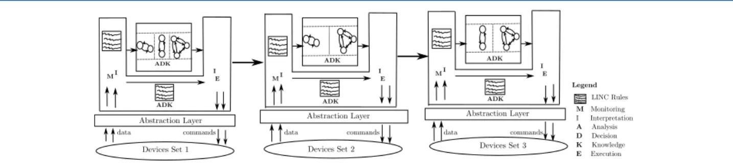
4.6 Handling a high number of devices
When the number of devices is high, using one single loop may become a bottleneck. First, the synthesis of the loop controller can take a lot of time or not succeed due to computing resource limitations. Second, the ex-ecution rule reads several data in its precondition part. This can lead to runtime performance degradation.
In this case, the devices can be partitioned in several sets. Then, one loop is used for each set, as illustrated
in Figure 8. In this context, each set of devices has a
controller. If the devices sets are independent, nothing more is required. Otherwise their controllers must be coordinated, using priorities on their actions on shared devices. In this case, an output value of a given con-troller can be an uncontrollable input for another one. The coordination of controllers is currently done in LINC. The execution rule of a controller can insert a value in specific bags or read a value inserted by an-other controller execution rule. The coordination could also be done in H/BZR, by exploiting the potential of
modular discrete controller synthesis, as done in [34].
5 Case Study
This section illustrates the proposed framework through a case study taken in the field of building automation. The aim is to manage the devices of a building in or-der to achieve a set of objectives. The building is first described. Then, its devices are managed and a demon-strator is presented to show that the framework was able to reliably achieve the target objectives. Then, the management cost is evaluated to show the scalability of our approach. Finally the case study is discussed to compare the framework to related work approaches. 5.1 Building description
The considered building consists of ten small offices and twelve big offices, that are separated. A small of-fice consists of a room that contains: a window, a shut-ter, a door, a lamp, a reversible air-conditioner (RAC), a mechanical ventilation (MV), a temperature sensor
and a CO2sensor. A big office has an additional lamp,
window, shutter and temperature sensor compared to a small office. A big office also has a presence sen-sor. Several sensors are installed outside the building
to enquire outdoor conditions (i.e., luminosity, CO2,
noise, temperature, pollen). Noise sensors are also in-stalled in the corridors. The actuators and sensors of the building use different communication technologies (e.g., EnOcean, TelosB). Each room has a file that de-scribes its devices (id, type, technology and location). Information about the meetings (e.g., day, time, fea-tures) that will be held in each room can be obtained through a specific agenda. The devices of the rooms must be managed to achieve the following objectives:
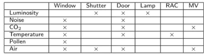
Table 1 Environment parameters and devices
Window Shutter Door Lamp RAC MV
Luminosity × × × Noise × × CO2 × × × Temperature × × × Pollen × Air × × × ×
• For comfort, when a presence is detected, the luminosity must be between 500 and 600 lux and the noise level must be lower than 80 dB; • For air quality, when a presence is detected and
the CO2exceeds 800 ppm, the room must be
ven-tilated. It must not be be polluted by pollen or
outdoor CO2 and must be quickly ventilated
be-tween meetings separated by less than 30 minutes; • For comfort, when a presence is detected and the
temperature is below 17 ◦C (resp. above 27◦C),
the room must be heated (resp. cooled);
• For confidentiality, the room must be com-pletely closed during a confidential meeting; • For energy savings, natural lighting,
ventila-tion, heating and cooling are preferred to artificial lighting, ventilation, heating and cooling.
5.2 Devices management using the proposed framework To achieve the objectives in the rooms, developers have to design a H/BZR program, from which a step func-tion and an execufunc-tion rule template will be generated. Then, developers have to write two monitoring rule templates to respectively estimate a presence in a small room (not equipped with a presence sensor) and to compute a temperature average in a big room (has two temperature sensors). Developers also have to write a monitoring rule template to know from an agenda, if there is a meeting or not and if a meeting will be held in less than 30 minutes, after a previous meeting. Fi-nally, the rule templates are instantiated in each room.
5.2.1 Designing a H/BZR program
This requires to design a generic model of a room. For this, a set of environment parameters are first
consid-ered (i.e., luminosity, noise, CO2, temperature, pollen
and air). Then, the effects of the devices on these
pa-rameters are specified. As presented in Table1:
• A window: affects five parameters (noise, CO2,
air, temperature, pollen). When the window is opened, it introduces the outdoor noise in the room. It can ventilate, heat or cool the room, de-pending on the outdoor conditions. It can pollute
the room by introducing pollen or outdoor CO2;
• A shutter: affects two parameters (luminosity, air). When the shutter is closed, it provides a lu-minosity equal to zero and stops the outdoor air;
+++++ MI MI M I I E I E I E
ADK ADK ADK
ADK ADK ADK
Devices Set 1 Devices Set 2 Devices Set 3
Abstraction Layer Abstraction Layer Abstraction Layer
Legend M Monitoring I Interpretation A Analysis D Decision K Knowledge E Execution LINC Rules data commands data commands data commands
Figure 8 Example of multiple loops for a high number of devices
• A door: affects five parameters (luminosity,
noise, CO2, temperature, air). When the door is
opened, it lights the room (if the corridor lamps are on) and introduces the corridor noise; • A lamp: affects one parameter (luminosity). It
provides 500 lux when it is on and 0 when off; • A RAC: affects the temperature of a room;
• A MV: affects the CO2 and the air.
A generic room model is obtained by designing au-tomata that describe the behaviours of a window, a shutter, a door, a lamp, a RAC and a MV. All the automata have an output flow that is the command to send to the modelled actuator. This command is equal to nothing when the actuator should not re-ceive a command. For instance, to switch off a lamp, the command is equal to s_off when the lamp is on and nothing as long as it remains off. The lamp and
shutter automata are those presented in Figure5.
Figure 9 presents the automaton that describes a
door. This automaton has two states and two tran-sitions. Each state is associated to two equations to produce the command of the door and also specify its effect on a room noise level. For instance, at the state Closed, the door affects the noise level with a value equal to zero. The effects of the door on the other
pa-rameters (i.e., air, CO2, temperature, luminosity) are
not considered because the corresponding sensors do not exist in the corridor and their values cannot be obtained. The transitions that go from a state to a different one are associated to not c. This allows to open or close the door only when necessary.
Figure10presents the automaton that describes the
behaviour of a reversible air-conditioner (RAC). This automaton has three states and six transitions. Each state is associated to three equations to produce the command of the RAC and also specify its effects on the room. For instance, at the state Off, the RAC does not cool nor heat the room. This automaton is contained in a node that has two input flows c1 and c2. The reason is that, at each state, three transitions can be triggered (i.e., two transitions that leaves the state and one that allows to stay). To associate a different
boolean expression to each of the three transitions of a state, at least two variables are needed. For instance, when the state Off is activated, if the input flow c1 is false, the RAC automaton goes to the state Cooling. If c2 is false, it goes to the state Heating. If both c1 and c2 are true, it remains at the state Off. Finally, if both c1 and c2 are false, at the same instant, the transition that was first declared is chosen. Associating not c1 and not c2 (resp. c1 and c2) to the transitions that leave (resp. come to) the state Off means that it is preferred to maintain the RAC Off for energy savings.
Figure11presents the automaton that describes the
behaviour of a mechanical ventilation (MV). This au-tomaton has three states. Each state is associated to three equations to produce the command of the MV
and specify its effect on the CO2 concentration of a
room. For instance, at the state Off, the MV does not ventilate the room. At Mode1, the MV ventilates the room but not quickly, as done in Mode2. The transi-tions that leave (resp. come to) the state Off are as-sociated to not c1 and not c2 (resp. c1 and c2) to express that it is preferable to not use the MV.
Figure12presents the automaton that describes the
behaviour of a window. This automaton has two states. Each state is associated to five variables to specify the effects of the window on different parameters of a room. At the state Closed, the window does not ven-tilate, heat, cool, pollute nor introduce outdoor noise in a room. At the state Opened, the window can heat, cool, ventilate, pollute or affect the noise level of a room, depending on the indoor and the outdoor con-ditions. The transitions that lead to a different state are associated to not c to specify that the window should be opened or closed only when necessary.
Once the devices modelled as automata, the H/BZR
node presented in Figure13is designed. This node
de-fine one instance of each device automaton and has a contract. The contract defines the target objectives and a set of controllable variables. These variables are the input flows associated to automata transitions with a value not given by the monitoring. The energy sav-ings objective (i.e., natural lighting, heating,
ventila-Door(c, co_noise) = cmd, noise Closed Opened not c not c cmd = close nothing noise = 0 cmd = open nothing noise = co_noise
Figure 9 Door automaton
O Cooling
Heating
Rac(c1, c2) = cmd, cool, heat
cmd = s_o nothing cool = false heat = false cmd = cool nothing cool = true heat = false cmd = heat nothing cool = false heat = true not c1 c1 not c2 c2 not c2 not c1
Figure 10 RAC automaton
tion and cooling are preferred) is expressed by declar-ing the controllable variables of the shutter and the window after those of the lamp, the RAC and the MV. This H/BZR node represents a room automaton. It takes as input sensor values and meetings information and returns the commands to send to the actuators.
Once defined, the H/BZR program (set of defined nodes) was compiled to generate a step function. The H/BZR program was also used to generate an execu-tion rule template that was instantiated for each room.
5.2.2 Execution rule template generation
The H/BZR program and the objects of the PUTUTU framework were used to generate an execution rule
template. This rule is presented in AppendixA
(List-ing 9). The precondition first applies nine rd
opera-tions on the Sensors bags of nine PUTUTU objects, referred as Objectname, to read the sensor values (e.g.,
presence, CO2). Then, the precondition applies a rd
on a bag that encapsulates an agenda to obtain infor-mation related to meetings. Finally, the precondition invokes the step with the sensor values and the meet-ings information to compute actuators commands. The performance of the rule template consists of two trans-actions. The first transaction verifies if the sensor val-ues did not change. Then, it applies six put opera-tions on the Actuators bags of six PUTUTU objects, referred as Objectname, to send the computed com-mand to the actuators. Finally, it updates the room generic model (changes the room automaton state). The second transaction sends a SMS to the mainte-nance if a command cannot be sent (e.g., commu-nication error, actuator failure). The execution rule
O Mode1 Mode2 MV(c1, c2) = cmd, ventil, quickventil cmd = s_o nothing ventil = false quickventil = false cmd = mode1 nothing ventil = true quickventil = false cmd = mode2 nothing ventil = true quickventil = true not c1 c2 c1 not c2 not c1 not c2 Figure 11 MV automaton
Window(c, i_co2, i_temp, o_co2, o_temp, o_noise, o_pollen, air) = cmd, ventil, heat, cool, poll, noise
Closed Opened not c not c cmd = close nothing ventil = false heat = false cool = false poll = false noise = 0 cmd = open nothing ventil = air o_temp < i_temp heat = air o_temp > i_temp cool = air o_temp < i_temp poll = air o_co2 > 500 o_pollen >80 noise = o_noise
Figure 12 Window automaton
template was instantiated in each room of the build-ing. For the big rooms, equipped with two lamps, two windows, two shutters, one RAC, one door and one MV, some computed commands (i.e., lamp_cmd, window_cmd, shutter_cmd) are sent to two actuators.
5.2.3 Monitoring rules design
A monitoring rule template is designed to estimate a
presence from the value measured by a CO2sensor, in
a small room. This rule template is the one presented
in Listing 5. Another monitoring rule template is
de-signed to compute a temperature average in a big room (is equipped with two temperature sensors). This rule
is presented in Listing8. The precondition of this rule
first reads two temperature values measured by two different sensors. Then, it uses a function to compute the average and stores it in the variable temp_aver. The performance of this rule stores the computed av-erage in the Sensors bag of the SoftSensors object. A monitoring rule template is designed to obtain rel-evant meeting information from a room agenda. This rule returns a resource that specifies if there is a meet-ing, if it is confidential and if meeting will be started in less than 30 minutes, after a previous meeting.
The designed monitoring rule templates were instan-tiated in specific rooms. This was done by replacing, in each operation, Objectname and id, respectively, with the technology and id of the corresponding sensor.
Room(i_presence, i_temp, i_co2, o_temp, o_co2, o_lum, o_noise, o_pollen, co_noise, meeting, con d, between2meetings) returns ( shutter_cmd, window_cmd, door_cmd, lamp_cmd, MV_cmd, RAC_cmd) contract enforce
i_presence lum in [500,600] i_presence noise < 80 i_presence ∧ i_temp ≤ 17 heat i_presence ∧ i_temp ≥ 27 cool i_presence ∧ i_CO2 ≥ 800 ventilation
meeting ∧ con d shutter Closed ∧ window ∧ Closed ∧ door Closed between2meetings quickventilation
not pollution
with (c1_lamp, c2_lamp, c1_RAC, c2_RAC, c1_MV, c2_MV,
c_shutter, c_window, c_door)
(shuttter_cmd, lum_shutter, air) = Shutter(c_shutter, o_lum); (lamp_cmd, lum_lamp) = Lamp(c1_lamp, c2_lamp); (door_cmd, noise_door) = Door(c_door, co_noise); (RAC_cmd, cool_RAC, heat_RAC) = RAC(c1_RAC, c2_RAC); (MV_cmd, ventil_mv, quickventilation) = MV(c1_MV, c2_MV);
(window_cmd, ventil_window, heat_window, cool_window, pollution, noise_window) = Window(c_window, i_co2, i_temp, o_co2, o_temp, o_noise, o_pollen, air);
lum = lum_shutter + lum lamp; noise = noise_door + noise_window; cool = cool_window ∨ cool_RAC; heat = heat_window ∨ heat_RAC; ventilation = ventil_window ∨ ventil_MV;
# equations
Figure 13 Room automaton
[ O b j e c t n a m e , " S e n s o r s " ] . r d ( i d , t e m p _ i d _ v a l ) & 2 [ O b j e c t n a m e , " S e n s o r s " ] . r d ( i d , t e m p _ i d _ v a l ) & CM : t e m p _ a v e r = a v e r a g e ( t e m p _ i d _ v a l , t e m p _ i d _ v a l ) 4 : : { 6 [ O b j e c t n a m e , " S e n s o r s " ] . r d ( i d , t e m p _ i d _ v a l ) ; [ O b j e c t n a m e , " S e n s o r s " ] . r d ( i d , t e m p _ i d _ a l ) ; 8 [ " S o f t S e n s o r s " , " S e n s o r s " ] . p u t ( temp_id , t e m p _ a v e r ) ; } .
Listing 8 Temperature average rule
5.3 Demonstrator with concrete devices
To illustrate the framework, a demonstrator was built. The aim is to achieve, in a room, two objec-tives: presence ⇒ luminosity in [500,600] lux, confidential meeting ⇒ room completely closed.
The demonstrator, as shown in Figure 14, consists of:
• A Plugwise circle [35]: Is a plug used to
auto-matically switch on or off the lamp. This is done by applying the operation put(id,command) on the Actuators bag of a Plugwise PUTUTU object.
• An EnOcean switch [36]: Is used as a
pres-ence sensor. The switch has a button that can be pressed to emulate a presence. The value of the switch (presence detected or not) is obtained by applying the operation rd(id, value) on the
Sen-sors bag of the EnOcean PUTUTU object.
• A graphical interface: Is used to emulate a shutter. A bag, contained in an object (Shutter), is created to send a command to the shutter. The insertion of a resource in this bag, shows the cor-responding action (open, close) on the interface.
Lamp Shutter Plugwise circle Raspberry Dongle 070140 EnOcean swicth PTM 210 Figure 14 Demonstrator
• A Raspberry Pi: Is used to deploy the objects and the execution rule. It is connected to the switch and to the circle through two dongles. Two bags (i.e., OutdoorLuminosity and Agenda) con-tained in an object (Room) were created to respectively emulate an outdoor luminosity sensor and an agenda for meetings. These bags were manually filled. The step function generated for the building was used.
Figure 15 presents the MIADIE-K loop that was
set up for the demonstrator. This loop is an
instan-tiation of the the generic loop presented in Figure 1.
Data are first collected through the abstraction layer: the Room object (outdoor luminosity and confidential meeting) and the EnOcean object (presence detected by the switch). Then, the collected data are used to invoke the step function that, based on the automata of the shutter and the lamp, computes and returns the commands that achieve the objectives without conflict. Finally, the computed commands are sent to the de-vices and the states of the two automata are changed. Several scenarios were performed to validate the demonstrator. Some scenarios were with a potential conflict (i.e. presence detected, outdoor luminosity in [500, 600] lux and confidential meeting held), com-munication errors or actuator failure (e.g., circle un-plugged). In all cases, there was no conflict and no inconsistency. Three examples of scenarios are:
• First scenario: The button of the switch was pressed to emulate a presence and the outdoor luminosity was set to 500 lux by inserting the re-source ("500") in the bag OutdoorLuminosity. A confidential meeting was also emulated by in-serting the resource ("confidentialMeeting") in the bag Agenda. This switched on the lamp and closed the shutter. The conflict which consists in opening the shutter for daylight and closing it at the same instant for confidentiality was avoided. • Second Scenario: It was performed just
af-ter the first scenario. The presence was still detected, the outdoor luminosity was equal to 500 lux, the shutter was closed and the lamp was on. In this context, the end of the con-fidential meeting was emulated by removing