HAL Id: cea-03254583
https://hal-cea.archives-ouvertes.fr/cea-03254583
Submitted on 8 Jun 2021
HAL is a multi-disciplinary open access archive for the deposit and dissemination of sci-entific research documents, whether they are pub-lished or not. The documents may come from teaching and research institutions in France or abroad, or from public or private research centers.
L’archive ouverte pluridisciplinaire HAL, est destinée au dépôt et à la diffusion de documents scientifiques de niveau recherche, publiés ou non, émanant des établissements d’enseignement et de recherche français ou étrangers, des laboratoires publics ou privés.
Design and flexible modeling of a long reach articulated
carrier for inspection
Joe Chalfoun, Catherine Bidard, Delphine Keller, Yann Perrot, Gérard Piolain
To cite this version:
Joe Chalfoun, Catherine Bidard, Delphine Keller, Yann Perrot, Gérard Piolain. Design and flexible modeling of a long reach articulated carrier for inspection. IEEE/RSJ International Conference on Intelligent Robots and Systems, Oct 2007, San Diego, United States. �10.1109/IROS.2007.4399213�. �cea-03254583�
Abstract— This work concerns the development of advanced
robotic systems for nuclear application. The manipulator will be used for light intervention in spent fuel management facilities. The robot must meet severe specifications: small diameter, long reach within a minimum range of 6 m, high dexterity to move in constrained environment and lots of degrees of freedom (DOF) for obstacle avoidance. In order to meet these requirements, a very challenging robotic carrier (called P.A.C.) which is able to perform light intervention tasks inside high range of blind hot cells using existing engineering penetrations is developed. This long reach multi-link carrier has 11 DOF and weighs less than 30 kg. The gravity effect in the manipulator is largely compensated by a special mechanical structure (the parallelogram) that helps reducing the size of the rotation actuators used to operate the robot. Also, a glass fiber epoxy equilibrium spring is used to compensate the gravity effect over the elevation actuators. A field test is made to measure the robot’s repeatability and accuracy by using a laser tracker to measure the end effector’s position. Due to its size and weight, this large robot manipulator holds lots of elastic and geometric deformations. Thus it possesses a very low accuracy. A mechanical model is developed to take into account the flexibilities of the structure. This flexible model will be used to improve the accuracy of the manipulator. Applications tests were made to evaluate the ability and performances of the system to meet the operational requirements. The operation took place in an existing decontaminated hot cell and it turned out to be successful.
I. INTRODUCTION
Large robots manipulators are needed in field, space and medical applications to perform different kind of tasks. Some manipulators are used in space systems maintenance[5],[8], for medical treatment assistance like the patient positioning system [6] or to perform maintenance or decontamination tasks in nuclear sites[1] [2],[3],[7].
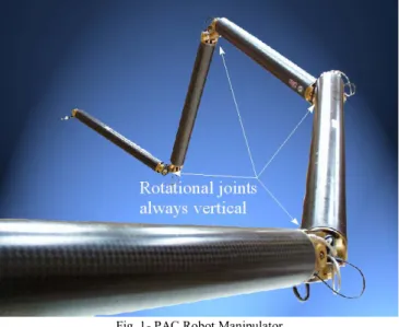
Most long reach manipulators are dedicated to operate in space application where gravity is nearly inexistent. Manipulators that are used on Earth, for nuclear applications for example, are subject to gravity which tends to oversize the actuators of the robot if not compensated for. In this paper the gravity effect in the manipulator in question is largely compensated by the mechanical structure (the parallelogram) that helps to reduce the size of the actuators embedded in the robot. The parallelogram has also another peculiarity of keeping the rotational joints (vertical) always
aligned with the gravity (Fig. 1).
Due to their large size, flexibilities are highly present in the structure of the long reach robot manipulators. For those that are used in space, vibrations in their structures can result from the end effector’s tool manipulation. But for the long reach manipulators that are used on Earth deformations are increased due to gravity. The geometric errors of a robot come from manufacturing imperfections, misalignments or joint backlashes. Compliance errors however are due to the flexibility of robot joints and link deflection under self-gravity and external load. If not compensated for, these undesired distortions can degrade the accuracy of the system, increase task times, reduce system safety, and in general make the overall control of the system more difficult.
Khalil et al [4] created a flexible model (links and the tool are represented like flexible beams) to compensate for the elastic errors in the system. They identified the geometric and flexible parameters of the PA 10 robot by using the generalized Jacobian matrix.
In this paper a more complete flexible model is developed that takes into account the deformations in the robot’s structure.
A world leading company in nuclear fuel manufacturing and reprocessing industry, expressed the need to carry out in its hot cells, light interventions with a long reach manipulator. The requested system must be deployed horizontally through a small diameter hole in a wide range of hot cells. A review of the state of the art highlights that there was no existing equipment meeting the severe specifications of the company: small diameter, long reach within a minimum range of 6 m, high dexterity to move in constrained environment and lots of DOF for obstacle avoidance.
In order to meet these requirements, a robotic carrier called PAC [1],[2],[3],[7] (Fig. 1) has been designed, manufactured and tested. Such technologies could be successfully extended to wide range of applications (Fission or Fusion facilities, decommissioning…).
This paper presents the PAC manipulator with an overview of the mechanical and control design principles. The mechanical design of the parallelogram and the gravity compensation mechanism are presented. The repeatability
Design and Flexible Modeling of a
Long Reach Articulated Carrier for Inspection
J. Chalfoun (1), C. Bidard(1), D. Keller(1), Y. Perrot(1), G. Piolain (2) (1) CEA, LIST, Service de Robotique Interactive
18 route du Panorama, BP6, FONTENAY AUX ROSES, F- 92265 France Phone : +33 1 46 54 78 79 ; Fax : +33 1 46 54 89 80 ; Email joe.chalfoun@cea.fr (2) AREVA NC F- 50444 Beaumont Hague Cedex, FRANCE Fax : +33 2 33 02 71 10
Proceedings of the 2007 IEEE/RSJ International Conference on Intelligent Robots and Systems San Diego, CA, USA, Oct 29 - Nov 2, 2007
and the accuracy of the PAC are measured with a Leica laser tracker LTD800. Due to its size and weight, flexibilities are highly present in the structure of this large robot. Thus it possesses a very low accuracy. These deformations are taken into account by developing a flexible model of the PAC. The aim of this model is to improve the accuracy of the manipulator. Then, descriptions of some of the PAC applications in a decontaminated nuclear cell are presented. At the end, a conclusion of the work is given and further developments are presented.
Fig. 1- PAC Robot Manipulator
II. DESIGN PRINCIPALS
A. Requirements
Summary of the requirements:
¾ Hot cell penetration hole not larger then 100 mm. ¾ Operational range over 6 meters of full extension, Able
to reach any point inside the cell, high mobility.
¾ Payload: inspection tool like a video camera (about 1 kg)
¾ Use of advanced remote control, user friendly interface, on line collision avoidance, Radiological conditions up to 10 kGy integrated dose for full life time, under max 10 Gy/hour dose rate.
¾ Safety: do not damage or pollute hot cell equipment
B. General design and control
The PAC is a long reach multi-link carrier that is formed by five segments and has 11 DOF: one translation movement of the base and two rotational movements for each segment (Fig. 2).
Fig. 2- Simplified PAC kinematics model with 11 DOF
In Fig. 2 the elevation axis are represented with a simple revolution axis. While in fact, it is a parallelogram structure that performs the elevation technique in order to minimize the impact of the cantilever structure (Fig. 3).
Fig. 3- PAC kinematics model with the parallelogram structure
The PAC weighs 30 kg and measures 6 m in full extension. Its tube diameter per segment measures 100 mm and is actuated by electrical motors. It can carry a payload of 1 kg at its end effector. It includes on-board hardened control electronics qualified up to 10 kGy. The PAC can be remotely operated by means of MAGRITTE (a teleoperation control system [3]) that provides all the functions necessary to remotely control manipulators including a graphical user interface providing 3D display of the manipulator (Fig. 4).
Fig. 4- PAC’s control thru MAGRITTE
Thanks to a passive 3D device (space mouse), the user can lead the head of the robot to key spots. The program also provides an on-line collision avoidance capabilities and real-time dynamic simulation which allows intuitive driving of the arm around the obstacles (pipes, tanks, ...).
Another method to pilot the PAC manipulator to a desired configuration is by manually entering the desired angles of the robot’s joints. The software accepts also a vector of desired configurations as inputs.
C. Mechanical design
The PAC carrier is composed of a set of 5 identical modules (1.2 m, 6 kg). Because of the high performance required for the mechanical structure (6 meters cantilever), high performances aluminum alloy and composite is intensively used. Each module is a two DOF mechanism: pitch and yaw joints. Although there are two rods in each module (Fig. 5), we consider that only one rod is under traction at any moment. Thus, each module is based on a four-bar mechanism (the parallelogram) composed of the rod, the first clevis, the tube and the second clevis (Fig. 5).
The parallelogram plays a major role in reducing the gravity effect over the joints of the structure by keeping the clevis vertical. Thus, the rotation axis, between the two clevis, will also be kept in a vertical position for any given configuration. This will reduce the size of the actuator that 4014
will rotate this module.
The rotation movement is set in motion by the actuators through a cable and pulleys system as shown in Fig. 6.
Fig. 5- Single module mechanical design
Fig. 6- Rotation cable system
A glass fiber epoxy equilibrium spring (Fig. 5), chosen for its high mass to potential energy ratio, plays a role in reducing the effect of gravity over the elevation actuators. It is attached to the clevis from one side and to the tube from the other side (Fig. 7).
Fig. 7- Gravity forces repartition in the parallelogram structure
The forces and tensions due to gravity over one of the modules of the PAC are represented in Fig. 7. The segments of the robot that follow the current one are modeled by a weight →P and a moment C→ applied over the clevis. When
performing a structural analysis to define the tensions created in the parallelogram structure, we find that:
1 3 1 2 1 . cos . cos A A A A L P C T d P T C T + = = = α α (1)
This implies that the tension T2 inside the spring is
independent from the moment and is only proportional to the weight of the structure that follows. The moment created by the other segments is absorbed by the rod and the tube.
The spring was designed to maintain the PAC in a horizontal plan at the position zero (α=0). At this position the tension in the spring is T2 =P.d0/A1. Where d0 is the
spring length at the position zero, the spring stiffness is 1
/ A
P
kj = . When the robot moves, P and
A
1 remainconstant, but the length d of the spring changes with the elevation angle α. The equilibrium system is not perfect for all configurations. Therefore, the gravity effect is not compensated for the entire working field of the robot. An Actuator is still needed for the equilibrium. It is situated inside the tube and rotates around a pulley situated over point A (Fig. 6 and Fig. 7). The spring can help with at least 80% of the force created by gravity at any given configuration. Thus, the actuator that will levitate this module has a reduced size.
Electrical actuators are preferred to hydraulic in order to avoid pollution and to turn the design easier. As far as no dynamic motion is required, high ratio gearbox with D.C. motors are satisfactory.
Since the lever arm A = 5 mm is very small compared to 1 the length of the spring, it is typically extended from 8.5 mm to 15 mm for the entire joint amplitude. This will produce a force in the spring between 50000 N and 85000 N. The maximal force in the rod is around 20000 N and the maximal compression force in the tube is around 105000 N (equivalent to 10 tons). When working in lateral position (second rotation axis at 90 deg), the maximal torsion in the tube is 250 Nm.
III. EXPERIMENTAL MEASUREMENTS
In order to determine the repeatability and the accuracy of the PAC, experimental measurements are conducted using a Leica laser tracker LTD800. This tracker has a precision of 0.01 mm/m and a range of 40 m. The experimental field that was made is depicted in Fig. 8.
A reflector (Fig. 9) is placed on the manipulator’s end for position measuring. A program developed at CEA LIST is specially made for this experimental field. This program synchronizes between the PAC controller and the LEICA controller. When a given configuration is attained, the program waits for the robot’s stabilization (about 10 s) and then launches the acquisition of the end effector’s position.
And then sends the next configuration to the PAC controller. This program is also designed to take several articular configurations as inputs and saves the corresponding end effector position.
Fig. 8- Experimental field with the Leica tracker
Fig. 9- The reflector
For the moment, the PAC is able to perform with only four segments and within a limited range of motion. When testing the repeatability of the PAC several positions were recorded and the manipulator was piloted at least 10 times for each position. A maximum of 1 mm of error was found on all the reached positions.
For the accuracy test, 520 configurations were taken to test the accuracy of the robot in the restricted field test. The measured position is compared to the theoretical rigid position. In the following Figures the error dX = (Xm-Xr) along the (x,y,z) axis is represented. Xm is the measured position and Xr is the calculated rigid position.
Fig. 10- Positioning error along the “x” axis
Fig. 11- Positioning error along the “y” axis
Fig. 12- Positioning error along the “z” axis
The error of the system which is the distance between the measured position and the rigid position is calculated by equation (2) and represented in Fig. 13. A maximum error of dmax = ||Xm-Xr||max = 4.7 cm and a mean error of dmean =
||Xm-Xr||mean = 2.6 cm are obtained.
2 2 2
(
)
(
)
)
(
X
mX
r xX
mX
r yX
mX
r zd
=
−
+
−
+
−
(2) 4016Fig. 13- distance (m) between the measured end effector’s position and the calculated rigid position
IV. FLEXIBLE MODEL
In order to improve the PAC’s accuracy, a flexible model that takes into account the deformations in the manipulator’s structure is developed.
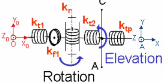
Each segment of the PAC is composed of a rotational axis and a parallelogram structure for the elevation movement (Fig. 14). The parallelogram will be subject to torsion, compression and traction. However, in order to simplify the complex calculations of the distortions in this structure, the torsion deformations will be delocalized and represented after the axis of elevation at the base of the parallelogram. Only compressions and tractions of the parallelogram structure are left in it. This way the parallelogram will always be contained in a 2D plane (Fig. 15). Each element admits one DOF in the traction/compression direction.
The torsion and flexion deformations of the structure, represented in Fig. 14, are modelled as follows (refer to Fig. 5):
1. A spring with kt1 stiffness that represents the torsion of the base or the first clevis before the rotational axis. 2. A spring with kf1 stiffness that represents the bending of
the rotational axis.
3. A spring with kr3 stiffness that represents the flexibilities in the rotational cables.
4. A spring with kt2 stiffness that represents the torsion of the second clevis after the rotational axis.
5. A spring with ktp stiffness that represents the torsion of the parallelogram structure.
6. A spring with kb1 stiffness that represents the flexibility of the connecting rod.
7. A spring with kj1 stiffness that represents the flexibility of the jack.
8. A spring with kt1 stiffness that represents the flexibility of the tube.
Fig. 14- PAC model
Fig. 15- Flexible parallelogram structure
These flexibilities will result in structure deformation. The flexibilities due to the torsion and flexion in the structure are introduced in the model as shown by the Fig. 16.
Fig. 16- Flexibilities around the axis of rotation
The Direct Geometric Model (DGM) of the rotation part described in equation (3) gives the position and orientation of the base of the parallelogram in the coordinate system locked in the centre of the rotational axis of each segment.
→ →
+
=R R R d R R R A
O x(ϕt1 ) z(ϕf1) y(θ θ ) x(ϕt2 ) z(α) x(ϕtb) (3)
The matrix
R
a is the homogeneous transformation matrix which rotation is made according to the “a” axis byϕ
angle. The DGM of the rotation axis is calculated in function of five generalized parameters(
ϕt1 ,ϕf1,θ,ϕt2,α,ϕtb)
Fig. 17- Parallelogram distortion due to flexibilities
The DGM of the parallelogram gives the position and orientation of the posterior clevis in the coordinate system of the base of the parallelogram. It is calculated in function of three generalized parameters
(
α,ltube,lrod)
.The DGM of a segment is the combination of the DGM of the parallelogram and the DGM of the rotational axis. And the DGM of the PAC is obtained by combining the 5 segments one after the other.
Fig. 18 depicts the algorithm for the calculation of the flexible model.This algorithm is similar to the one employed by Khalil [4], but differs in the calculation method. The calculation starts with the rigid model. For a set of desired configurations and using the generalized parameters and the geometrical properties of the structure the DGM of the PAC is calculated. When introducing the flexibilities of the structure and the gravity effect imposed upon it, the efforts applied on the links and joints are calculated which yields to the deformation computation. These deformations are used to upgrade the generalized parameters of the robot and are compared to the previously calculated ones. If the difference between the new and the old deformation vector is close to zero, the flexible model is obtained. If not, then a new
iteration is performed which rectifies the old model by using the new generalized parameters. This algorithm is repeated till convergence. About three to four iterations are required to obtain a difference below 10-6 m or radiant between the deformation variables.
Fig. 18- Flexible model algorithm
When comparing the measured position with the flexible calculated position Xf a maximum error of (Xm-Xf)max = 4.2 cm and a mean error of (Xm-Xf)mean = 2.2 cm are obtained (Fig. 19)
The flexible model did not reduce by much the positioning error of the system when using the nominal parameters of the PAC. However, previous research like [4],[6] have proven that by performing a calibration method to identify the parameters of the system, the positioning error can be further reduced. Thus, our next step would consist on developing a calibration method to identify the parameters of the PAC. The goal would be to find the parameter vector popt that minimizes the position error ∆X=(Xm-Xf) for a given number of configurations. The identifiable parameters are the mass, the length, the position of the center of gravity and the stiffness of the different parts of the robot.
Fig. 19- distance (m) between the measured end effector’s position and the calculated flexible position
V. PACAPPLICATIONS AND TESTS
This phase concerns the evaluation of the performances and the capabilities of the robot in a hazardous and limited access area. This was performed during field tests in an existing decontaminated hot cell.
The tests are carried out in a full operational cell with real equipment (Fig. 20). This cell was free of radiological conditions. Therefore, it was possible to enter the cell to evaluate the robot performances, accuracy of trajectories and capability of the whole system to meet mission requirements.
The tests involve a close visual inspection of pipes (Fig. 21), maneuverability between cell components (Fig. 20) and a contact test with a pipe (Fig. 22).
By using the space mouse, the operator could easily drive the head of the robot along the pipe to achieve the tasks.
Main scope of the test campaign is: ¾ To test a set of realistic operational tasks.
¾ To test a full intervention scenario from introduction to draw back.
¾ To point out design limitations.
¾ To check robot dexterity to avoid real obstacles.
¾ To check operational performances of visual inspection process.
¾ Accuracy of the control system based on a 3D monitoring.
Fig. 20- Test Cell
Fig. 21- Inspection of a pipe
Fig. 22- Simulation of a contact task
Reconnaissance of pipes and components is performed easily with the video process. Close inspection of pipes gives sufficient quality images to accurately analyze the state of the installation. Measurements acquired along these tests bring confidence to draw sustainable analysis of cell state and diagnostic of possible events.
VI. CONCLUSION AND FURTHER DEVELOPMENTS
The conclusion of this study is a successful operation of the PAC robot during the field test campaign in a real hot cell. A description of the mechanical model of the PAC with its special parallelogram structure was introduced. A flexible model of the PAC taking into account the deformations in the structure was developed. The ability of the robot to perform inspection and light intervention in a constrained environment was demonstrated.
Due to its large structure and flexibilities the accuracy of the PAC is very poor. Therefore, a calibration method of the flexible model taking into consideration the flexibilities of the structure is under development. This technique is used to identify the model’s parameters, like the constraints, the center of gravity, the mass and length of the components, to
reduce furthermore the error.
The industrialization of the PAC has begun. The robot will be called LORA short for LOng Reach Arm. This new design differs from the PAC by several points including a bigger tube diameter (160 mm), higher degrees of freedom (15 DOF), a bigger work field for the robot and it can carries a bigger payload up to 10 kg.
ACKNOWLEDGMENT
This work has been performed in the framework of a common research program associating CEA LIST (The Interactive Robotics Unit) and AREVA NC Company (Reprocessing Business Unit).
REFERENCES
[1] J.M. Alexandre “Rad hard electronics developments for robotic applications”, ANS 9th Topical meeting on Robotics and remote systems, 2001, Seattle (USA).
[2] J.P Friconneau and Y. Perrot, “Development of a long reach articulated carrier for inspection in spent fuel management facilities”, ANS 9th Topical meeting on Robotics and remote systems, 2001,
Seattle (USA)..
[3] P. Gicquel, C. Andriot, F. Coulon-Lauture, Y. Measson and P. Desbats, “TAO 2000 : A generic control architecture for advanced computer aided teleoperation systems”, ANS 9th Topical meeting on
Robotics and remote systems, 2001, Seattle (USA).
[4] W. Khalil and S. Besnard, “Geometric calibration of robots with flexible joints and links”, Journal of Intelligent and Robotic systems, vol 34, 2002, pp 357-379.
[5] C. Mavroidis, P.Rowe and S. Dubowsky, “Inferred endpoint control of long reach manipulator systems,” Proceedings of the International Conference on Intelligent Robots, IROS 95, Pittsburg, PA, Vol. 2, 1995, pp. 71-76.
[6] M. Meggiolaro, S. Dubowsky and C. Mavroidis, “Geometric and elastic error calibration of a high accuracy patient positioning system”, Mechanism and Machine Theory, vol 40, 2005, pp 415–427.
[7] Y. Perrot, L. Chodorge, P. Desbats, JP. Friconneau and G. Piolain, “Scale one field test of a long reach articulated carrier for inspection in spent fuel management facilities”, ANS 2004, Gainsesville, Florida, USA.
[8] M.A. Torres, S. Dubowsky and A. Pisoni, “Path-Planning for elastically mounted space manipulators: experimental evaluation of the coupling map,” Proceedings of the 1994 IEEE International Conference on Robotics and Automation, May 1994, San Diego, CA, pp. 2227-2233.